II. Hardware Design Details
Power Supply Circuit Design:
This project uses an LDO (Low Dropout Linear Regulator) as the power supply. Considering the actual application scenario, the SE8550K2 with a maximum input voltage of 40V was selected. A DC-DC step-down circuit was not used primarily to avoid potential ripple interference and to reduce costs.
MCU Selection Analysis:
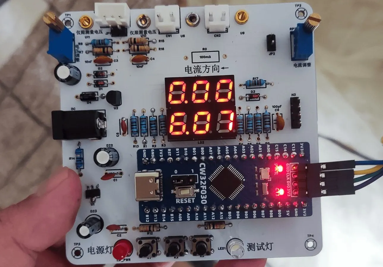
This project uses the LCSC CW32F030C8Tx development board as the main controller. The selection considered computing power, I/O ports, and peripheral requirements. The CW32's advantages lie in its wide operating temperature range, wide operating voltage, strong anti-interference capability, and excellent ADC performance.
Voltage Sampling Circuit Design :
The voltage divider resistors are designed as 220K+10K, with a voltage division ratio of 22:1. Considering safety factors, the maximum measured voltage is designed to be 30V, but it can actually display 99.9V or 100V. The ADC reference voltage is 1.5V, which can be configured through the program. To reduce power consumption, the low-side resistor is selected as 10K. Calculations show that the high-side resistor is 220K. For measuring lower voltages, the voltage divider resistor can be replaced and the program modified to improve accuracy. For measuring higher voltages, the voltage reference can be increased to expand the range.
The current sampling circuit design
uses a low-side current sampling circuit with a designed sampling current of 3A and a sampling resistor of 100mΩ. Considering the voltage difference, power consumption, and amplification factor caused by the current sensing resistor, a 1W packaged metal wire-wound resistor was selected. To cope with different operating environments, especially high-current scenarios, the R0 resistor can be replaced with constantan wire or a shunt.
The digital tube display design
uses two 0.28-inch three-digit common-cathode digital tubes as display devices. Compared to a display screen, digital tubes have better recognition in complex environments and better mechanical performance. The current-limiting resistor is configured with 300Ω to achieve good display effect. The digital tube uses a dynamic scanning display driving method.
The LED indicator design
includes an additional power indicator and an IO working indicator. The power indicator LD_PWR is active low (on), and to reduce the current consumption of the LED, a 10K current-limiting resistor was selected.
The button
control circuit is designed to be simple, thanks to the CW32's internal I/O ports which can be configured with pull-up and pull-down resistors, eliminating the need for external configuration. One end of the button is connected to the MCU's I/O, and the other end is grounded. When the button is pressed, the I/O is pulled low. An additional
TL431
circuit is added to provide a 2.5V reference voltage, which can be used to provide an external voltage reference for calibrating the AD converter. The TL431 is a precision programmable reference device with high accuracy, adjustable output voltage, and a certain amount of current sinking capability. In this project, it is mainly used to learn the relevant application principles.


 京公网安备 11010802033920号

 REC3-2415RW


