A simple digital oscilloscope, made following the instructions in the training camp.
Simple digital oscilloscope.
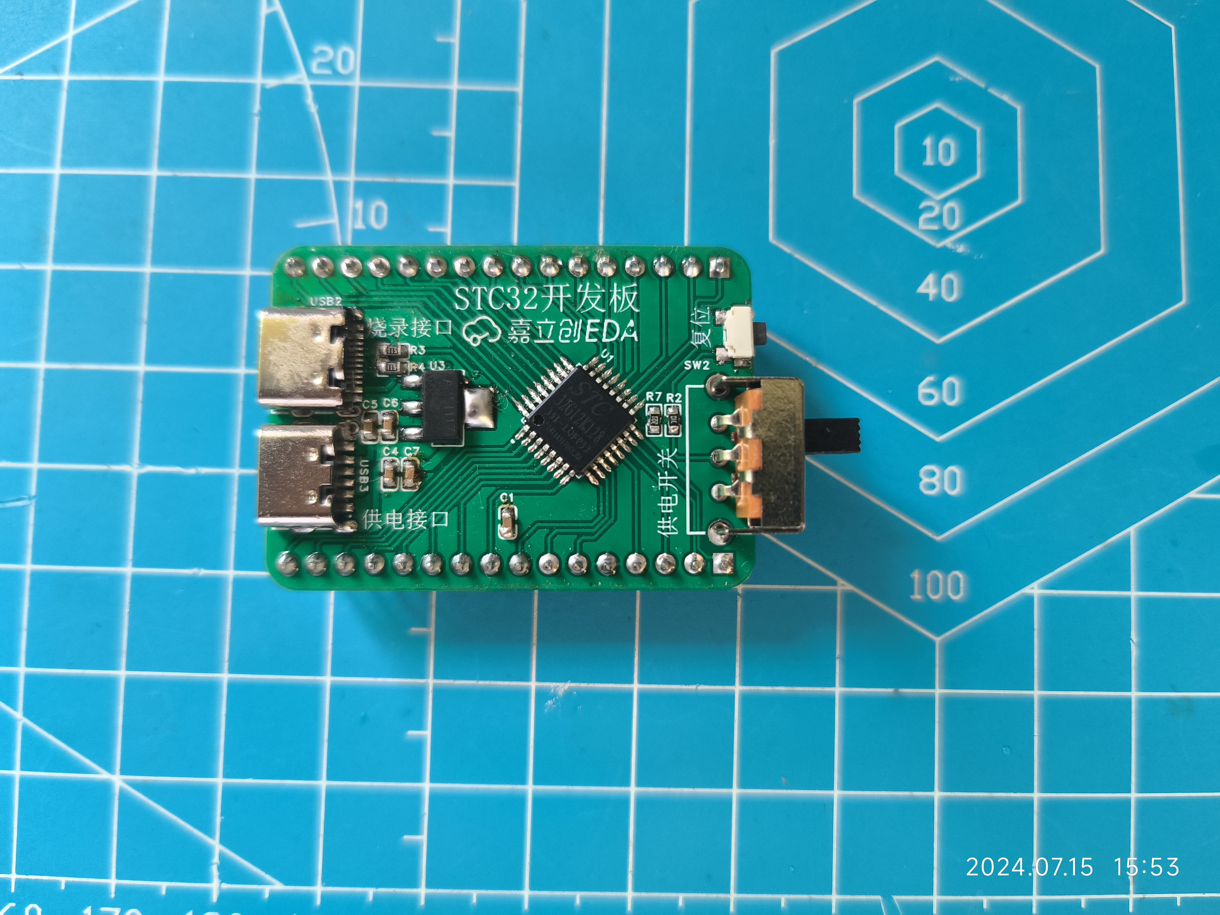
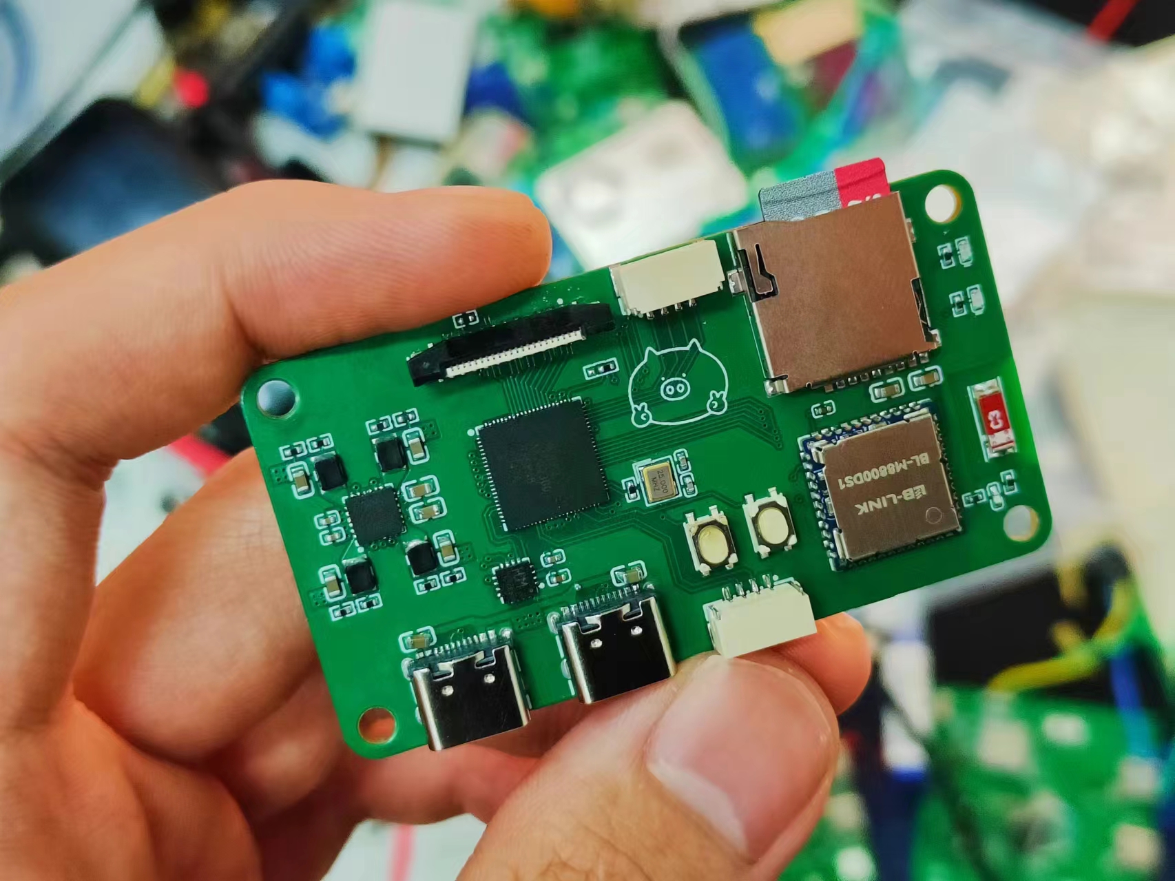
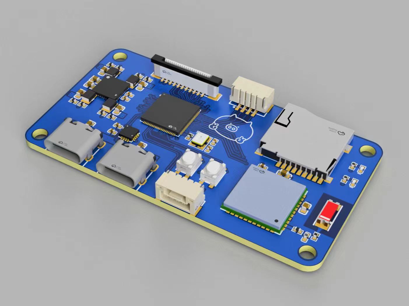
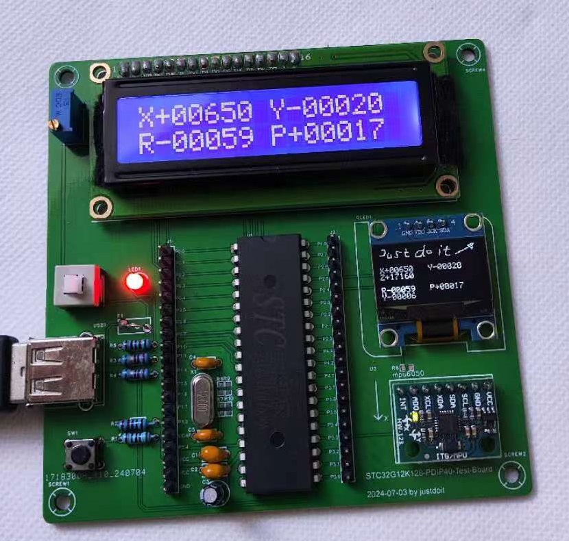
51 test board based on chip STC32G12K128.
A snowflake light base based on TP5400, perfectly solving the automatic sleep mode issue under low current conditions for IP5306/FM5324GA!
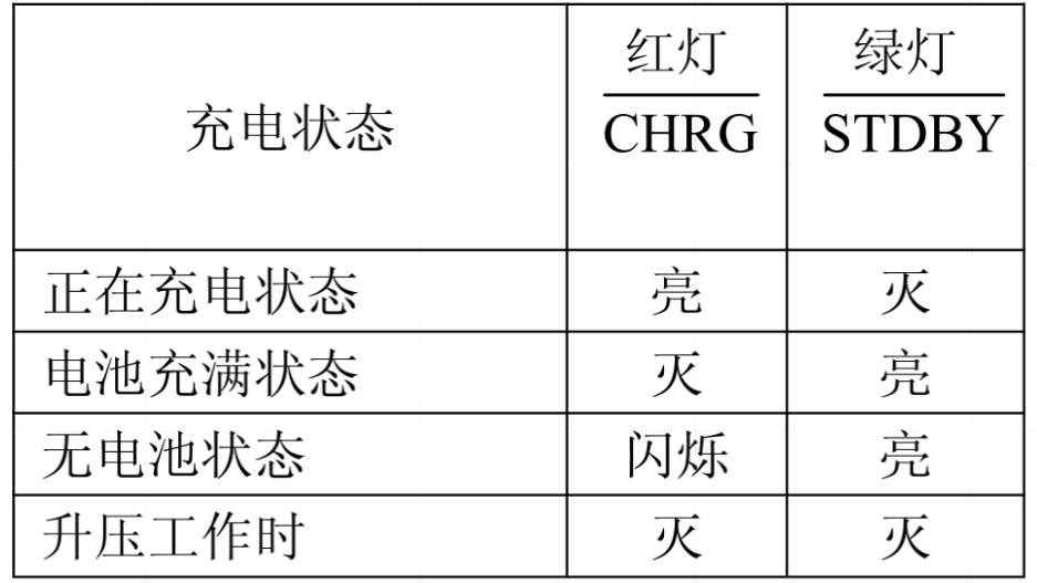
Overview of the TP5400-based Battery Charge/Discharge Boost Module (Snowflake Light Base 2.0):
The TP5400 is a dedicated single-cell lithium-ion battery charger and constant 5V boost controller for power banks. The charging section integrates high-precision voltage and charging current regulators, pre-charge, charging status indication, and charging cutoff functions, capable of outputting a maximum charging current of 1A. The boost circuit utilizes a VFM switching DC/DC boost converter manufactured using CMOS technology, exhibiting extremely low no-load current. It features very low no-load power consumption (less than 10uA) and a boost output drive current capability of up to 1A. It requires no external buttons and is plug-and-play.
The charging section employs a linear buck converter with a built-in PMOSFET and anti-reverse current circuitry, eliminating the need for external sensing resistors and isolation diodes. Thermal feedback automatically adjusts the charging current to limit chip temperature under high-power operation or high ambient temperature conditions, with the fully charged voltage fixed at 4.2V. The charging current can be externally set via a resistor. Once the battery reaches 4.2V, the charging current gradually decreases to 1/5 of the set current value, and the TP5400 will automatically stop charging. The boost section also integrates a power NMOSFET, whose low internal resistance provides a drive capability of 5V/1A. The high integration allows the TP5400 to operate normally with only a few external components. The TP5400 also integrates charging temperature protection, a boost input power current limiting loop that dynamically adjusts the current according to the load, and features fast response and overcurrent shutdown. The boost converter uses a frequency conversion method, resulting in significantly lower no-load power consumption, ripple, stronger drive capability, and higher efficiency compared to similar products both domestically and internationally.
The introduction
is the same as version 1.0, nothing much to say, just look at the pictures! The picture shows
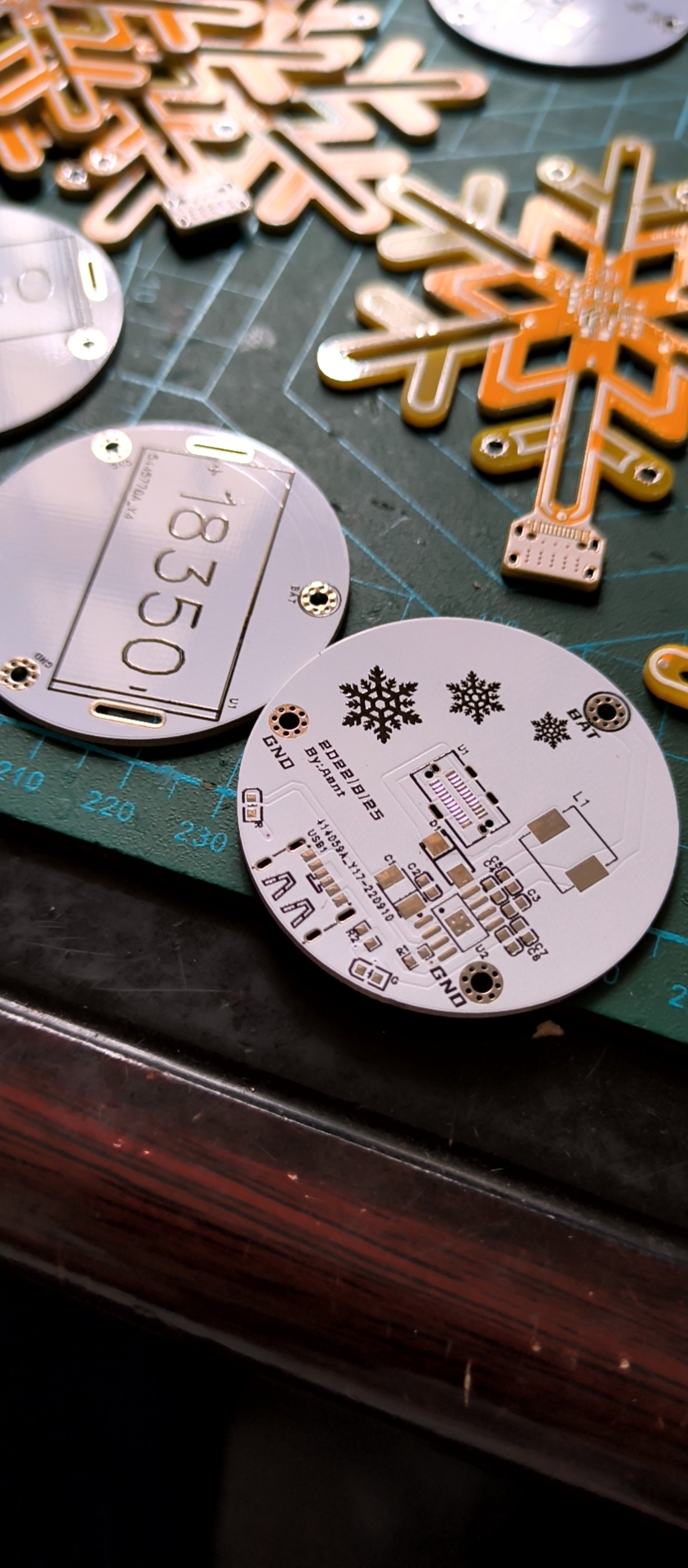
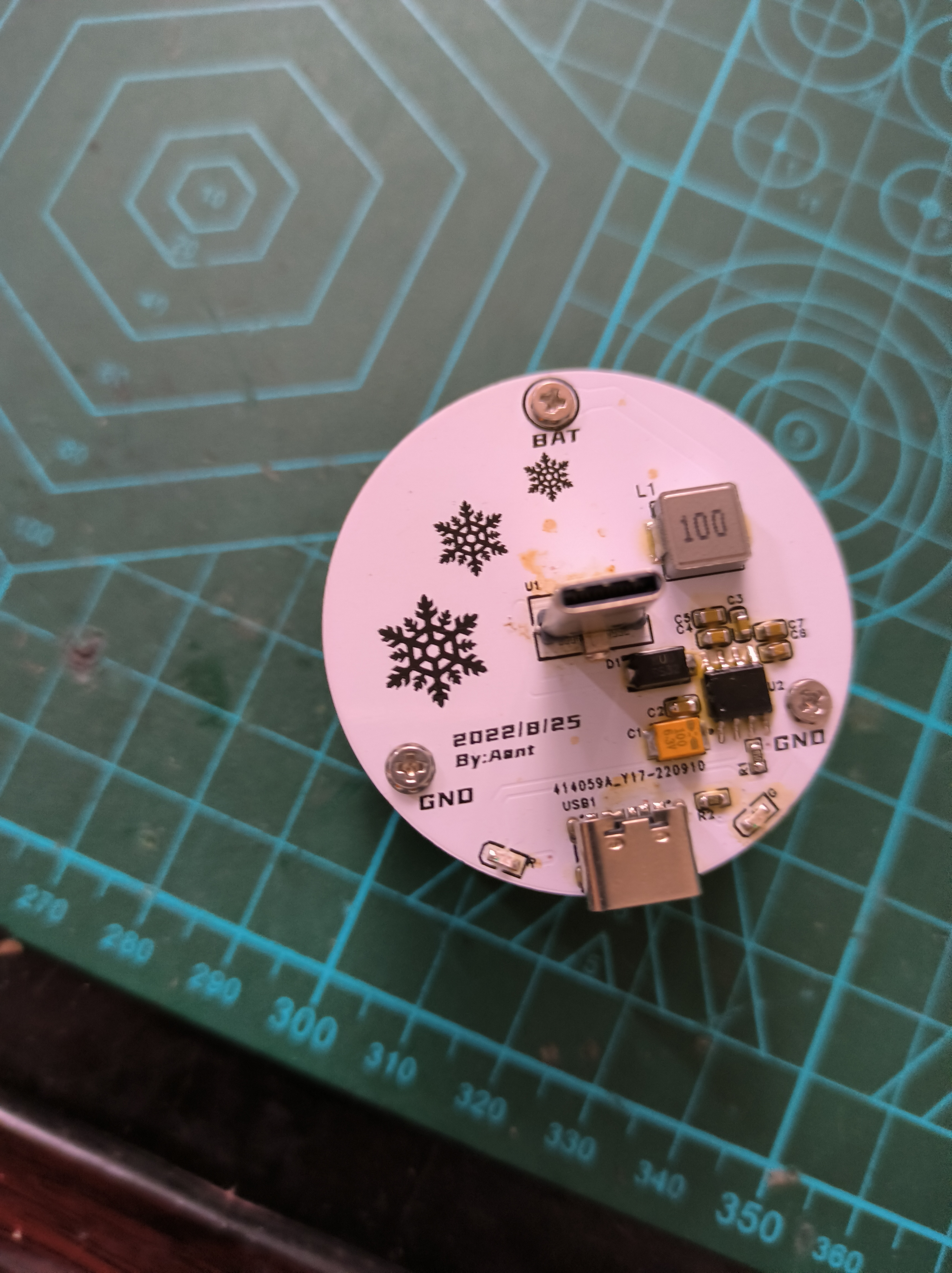
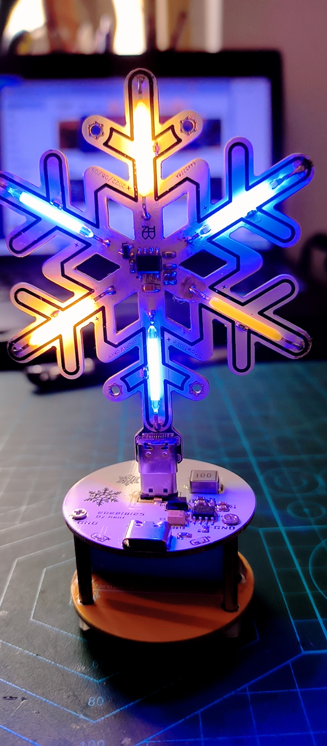
the LEDs are soldered in the wrong colors; the right side is red, and the left side is green. The finished product
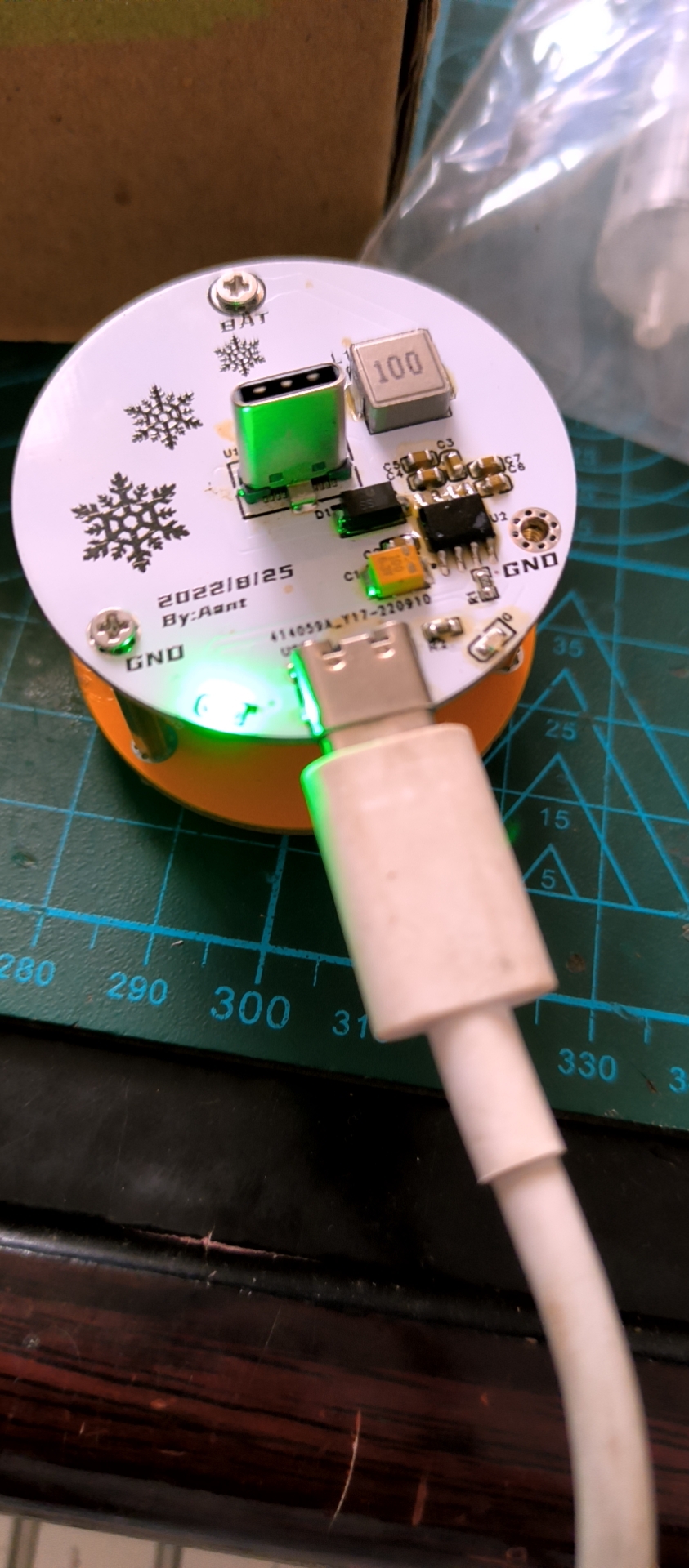
supports both the lowest and highest brightness levels for the snowflake LED. No more precautions. LED status indicates no short circuit. Known issues: 1. Green indicator light is not on; currently unsure of the problem (I'm a high school student and don't have much time; I'll look into the cause during my next holiday!!!). 2. None.
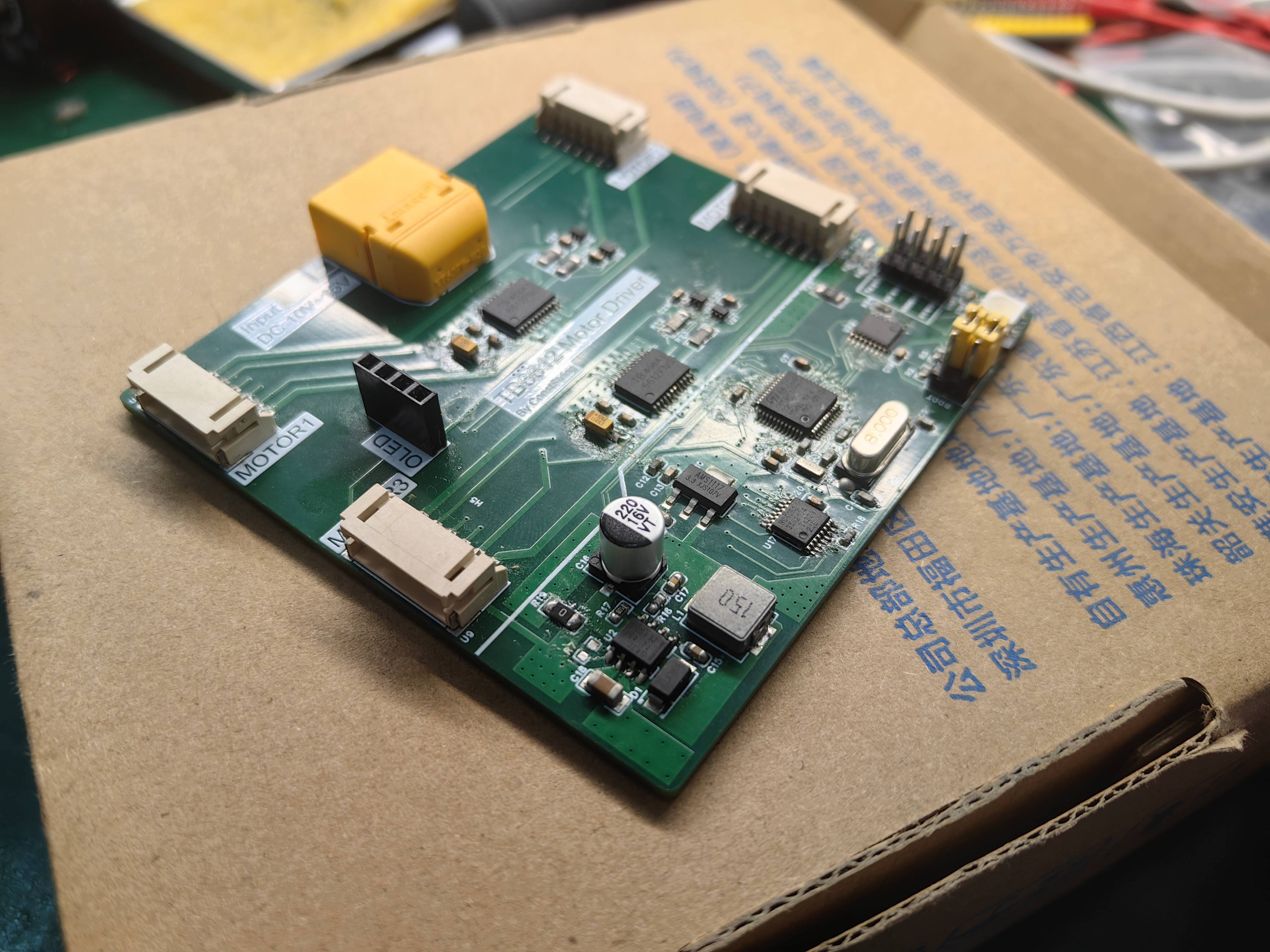
[Top Choice for Small Cars] TB6612 Four-Channel Motor Driver, Includes Speed and Current Detection
The TB6612 is a four-channel motor driver that includes speed and current detection. It features an onboard STM32F103C8T6 microcontroller. After programming, the driver can drive four motors by sending commands to the driver board via serial port and perform closed-loop control of speed and current.
Project Overview: This project utilizes
the TB6612 four-channel motor driver, which includes speed and current detection. It features an onboard STM32F103C8T6 microcontroller. After programming, commands are sent to the driver board via serial port to drive the four motors and perform closed-loop control of speed and current.
Using this driver board, the host computer only needs two I/O pins to drive the vehicle, making it a general-purpose solution for vehicles, avoiding repeated development and reducing workload.
The onboard microcontroller control code is pre-packaged and can be directly programmed for convenient and quick use.
Implementation Details:
Motor Drive:
The motor drive uses two TB6612 microcontrollers, resulting in minimal heat generation.
Current
detection uses four INA199 microcontrollers and four 0.5R sampling resistors to detect the current of each motor. An ADC is used to read the current value, which can be used for power limiting and overcurrent protection .
Speed detection
uses a frequency measurement method, measuring the pulse period of a Hall sensor using a timer. For four motors, a multiplexer is used to collect pulse signals in a time-division multiplexing manner, and the speed of the four motors is collected through polling.
Other peripherals include
RGB1 and
OLED1,
with onboard 12V-5V DC-DC converters that can power other devices.
Instructions
: 1. The power interface uses an XT60 connector, directly connected to the power battery.
2. Current detection can be left unsoldered. Finished
product effect.
mortor_driver_2024-07-15.epro
PDF_【Top Choice for Small Cars】TB6612 Four-Channel Motor Driver, Including Speed and Current Detection.zip
Altium_【Top Choice for Small Cars】TB6612 Four-Channel Motor Driver, Including Speed and Current Detection.zip
PADS_【Top Choice for Small Cars】TB6612 Four-Channel Motor Driver, Including Speed and Current Detection.zip
BOM_【Top Choice for Small Cars】TB6612 Four-Channel Motor Driver, Including Speed and Current Detection.xlsx
93736
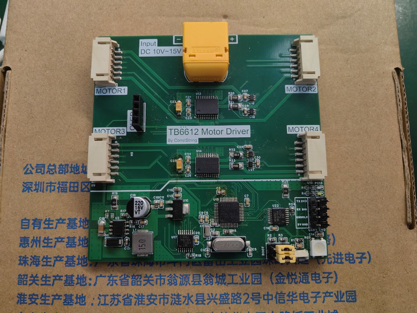
#Training Camp# Simple Digital Oscilloscope Based on GD32 - 1689246A
This is a GD32 simplified digital oscilloscope competition project organized by LCSC Training Camp. I made only major modifications to the component layout based on its open-source materials.
This simple digital oscilloscope is designed based on the LCSC GD32E230C8T6 development board.
It uses digital circuitry and digital storage technology to digitize waveforms and display them on an OLED screen. The measurement range is low frequency.
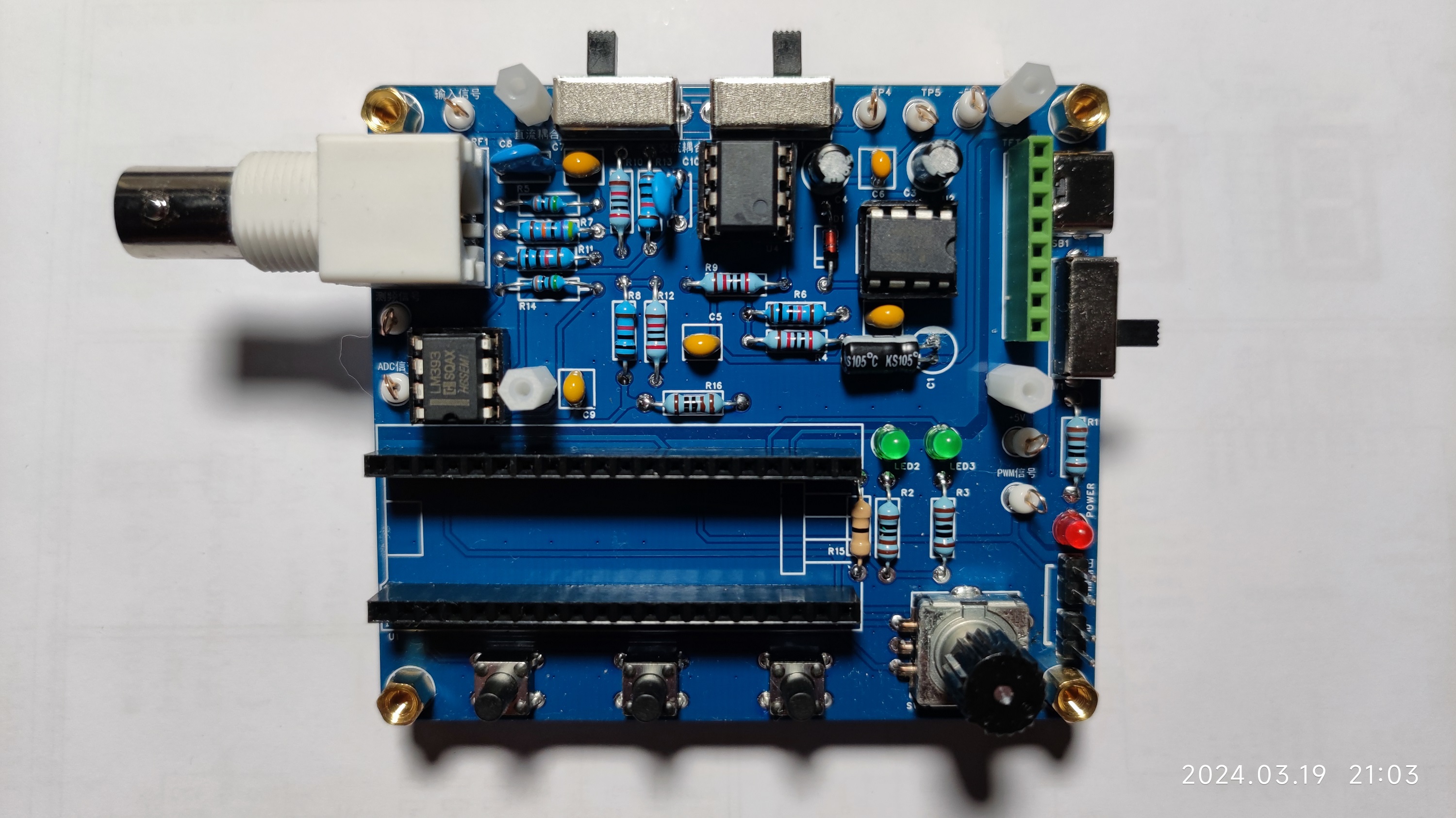
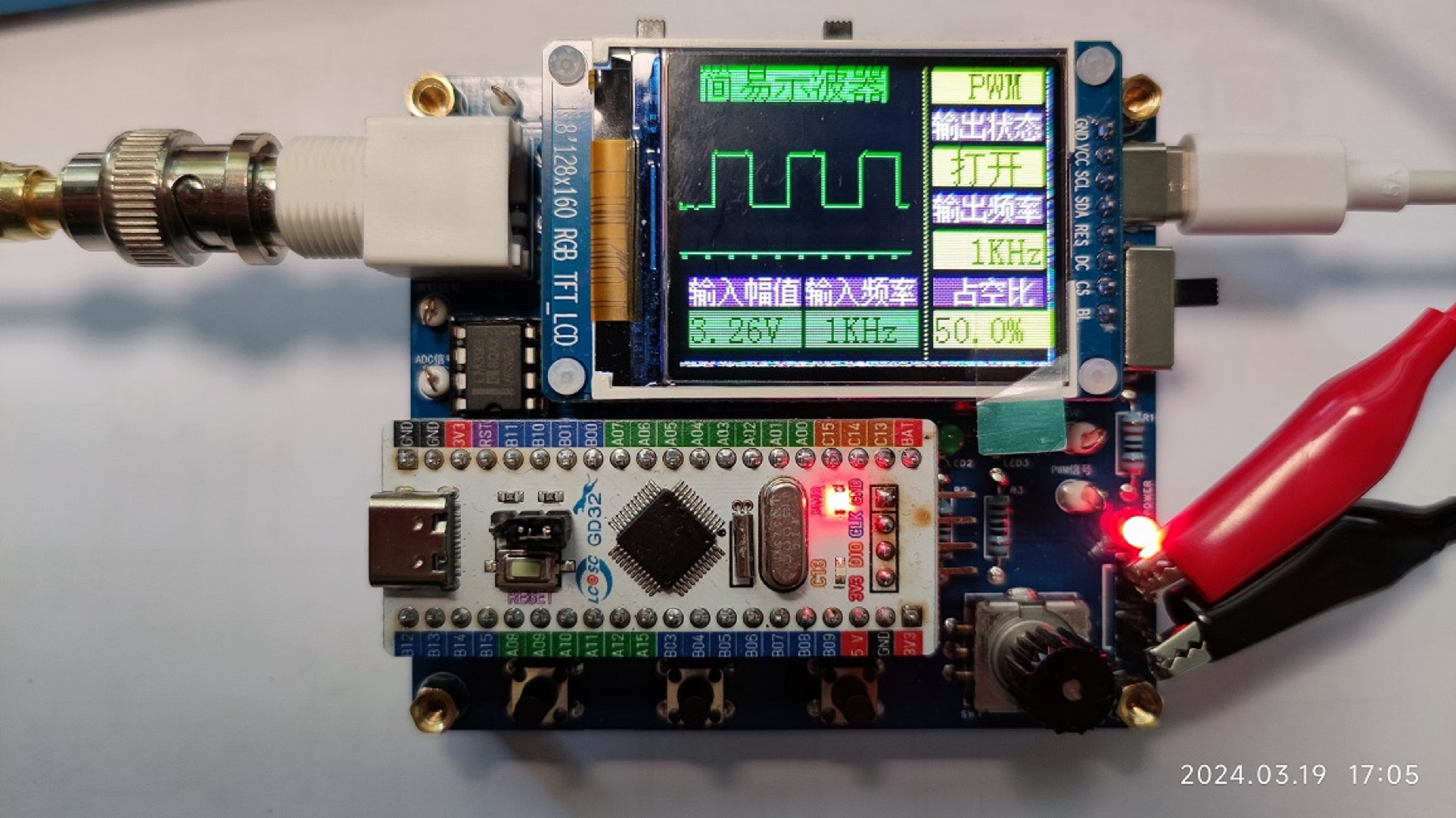
This is the PCB after the components have been soldered. The circuit uses through-hole components, so the soldering skill requirements are not high.

While working on this project, I learned about microcontrollers, analog circuits, digital circuits, LDOs, DC-DCOs, LEDs, and related software applications.

PCB prototyping was free. However, designing a perfect PCB is not easy; it's not an exaggeration to say it went through several revisions.
There were coupons for purchasing components, making it essentially zero cost. However, component selection requires some thought, especially in self-designed circuits. A mistake can lead to incorrect packaging, soldering failures, or even a ruined PCB.
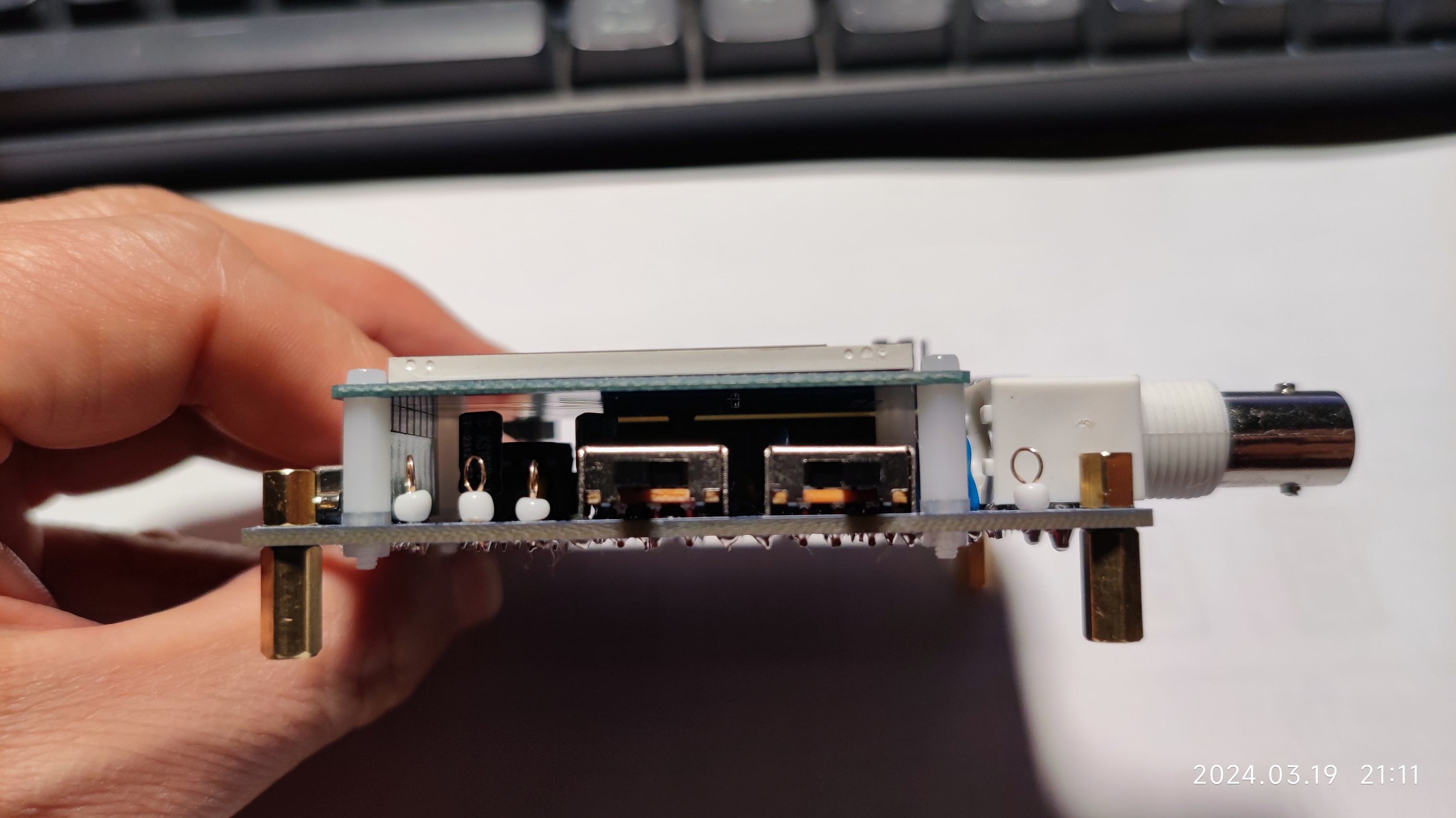
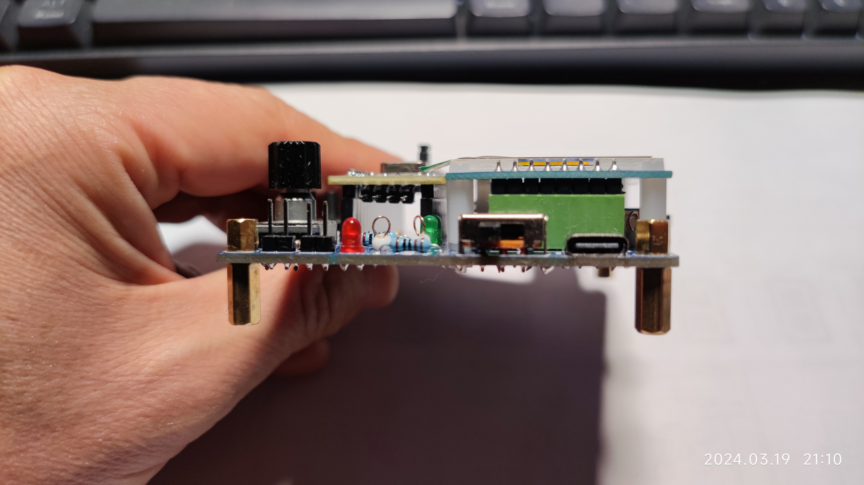
Copper pillars were added as a base to prevent short circuits at the bottom.

The uncertain height of the test lead sockets caused me to make significant changes to the component layout. One result was that the component placement was very complicated; another was that the wiring was unsatisfactory and messy.

The PCB component layout was repeatedly modified. One lesson learned: meticulousness is a must for electronics enthusiasts.
Was the waveform reversed due to insufficient study of circuit theory, or carelessness?
This project, from circuit schematic design (replication) to component selection, PCB layout and routing, and PCB prototyping—a complete process—improved an electronics enthusiast's practical skills in transforming blueprints into physical components. This is the most important aspect.
This oscilloscope isn't very powerful, but through this small project, it has gradually improved and strengthened the skills of novice electronics enthusiasts like us.
Many thanks to JLCPCB EDA for their support and contributions.
202403192149.mp4
PDF_#Training Camp# Simple Digital Oscilloscope Based on GD32 - 1689246A.zip
Altium_#Training Camp# Simple Digital Oscilloscope Based on GD32 - 1689246A.zip
PADS_#Training Camp# Simple Digital Oscilloscope Based on GD32 - 1689246A.zip
BOM_#Training Camp# Simple Digital Oscilloscope Based on GD32 - 1689246A.xlsx
93738
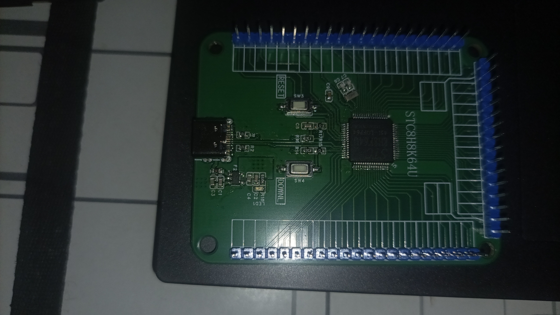
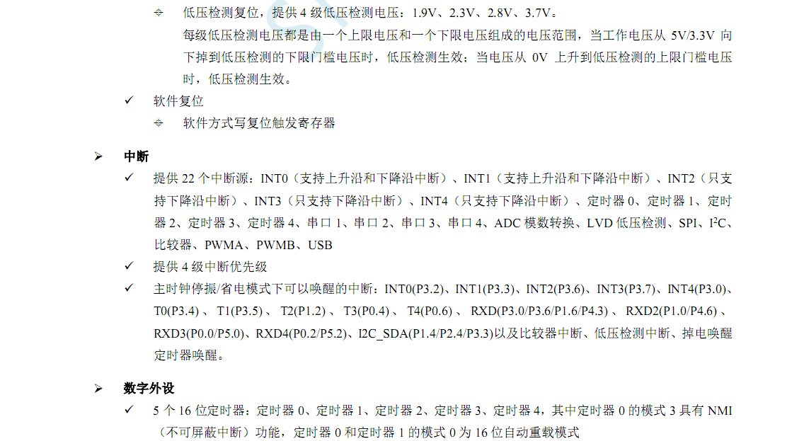
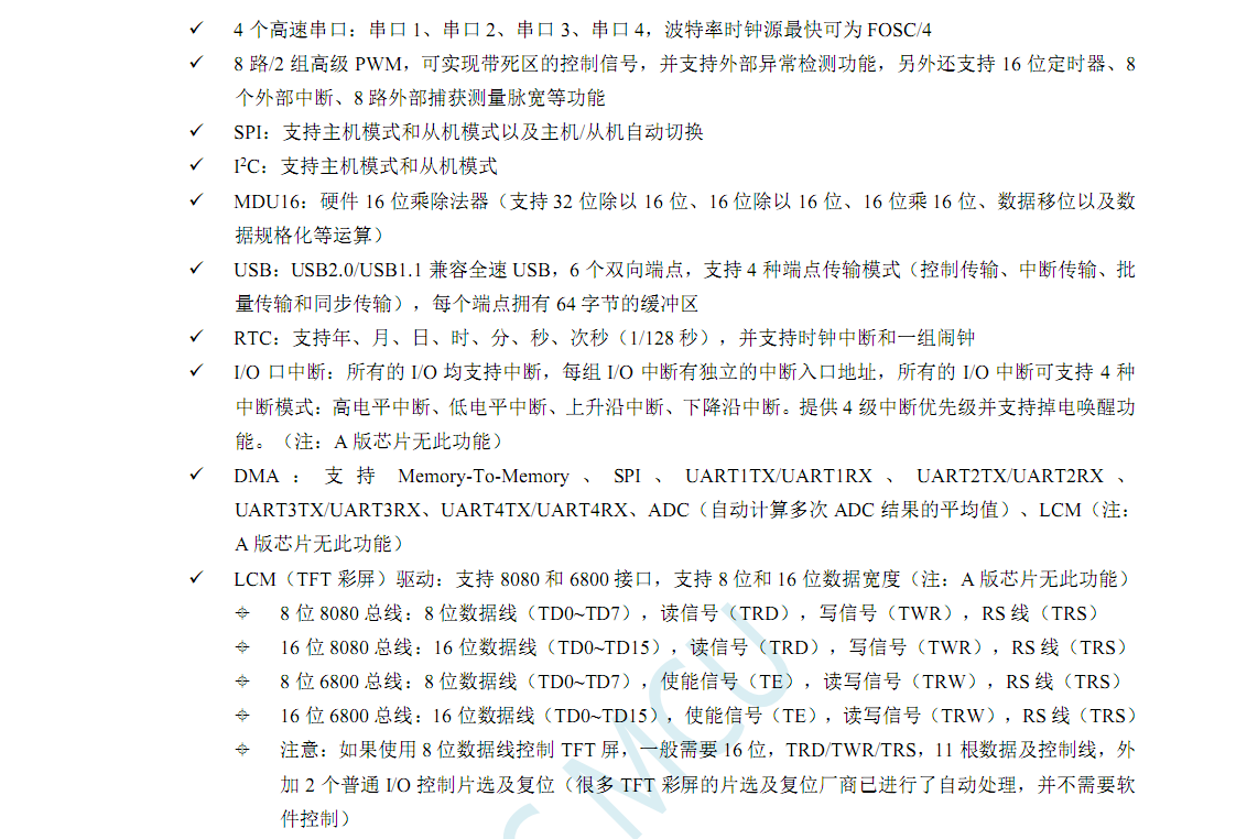
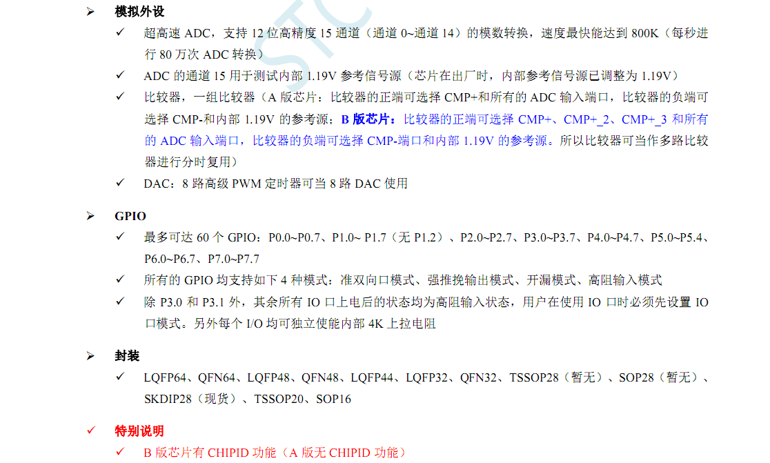
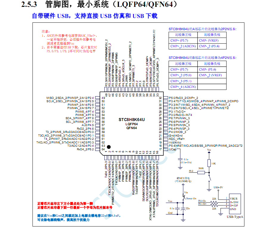
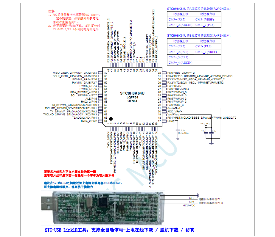
STC8H8K64U Minimum System Board Microcontroller Design
STC8H8K64U Minimal System Board, Microcontroller Design, LQFP64 Package
The task requires participants to design a
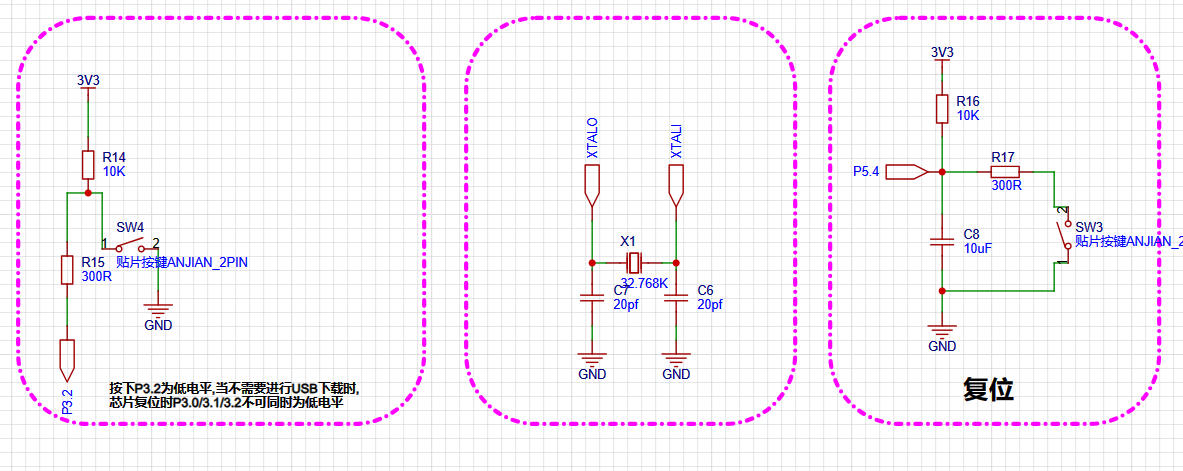
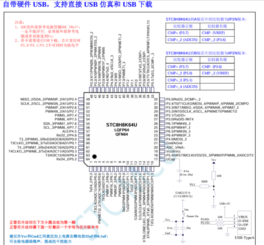
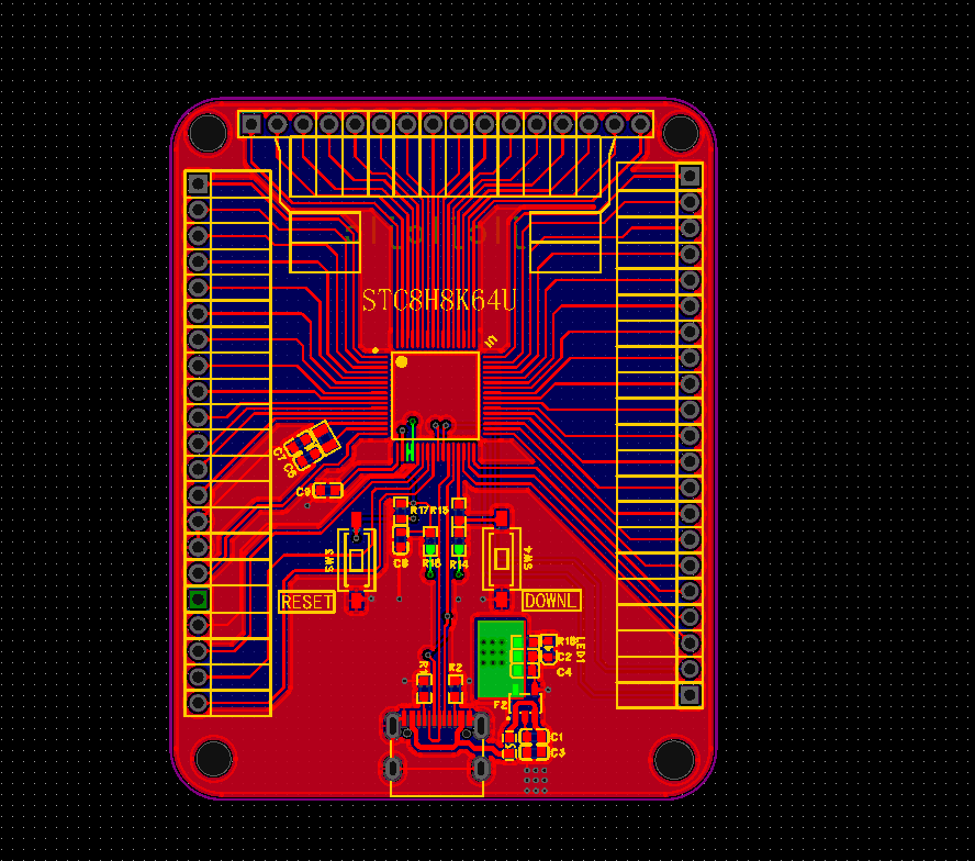
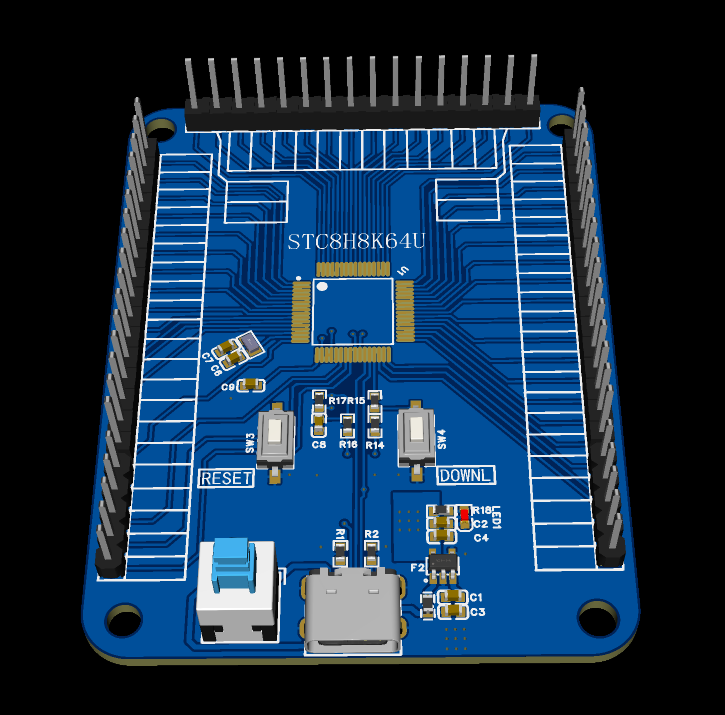
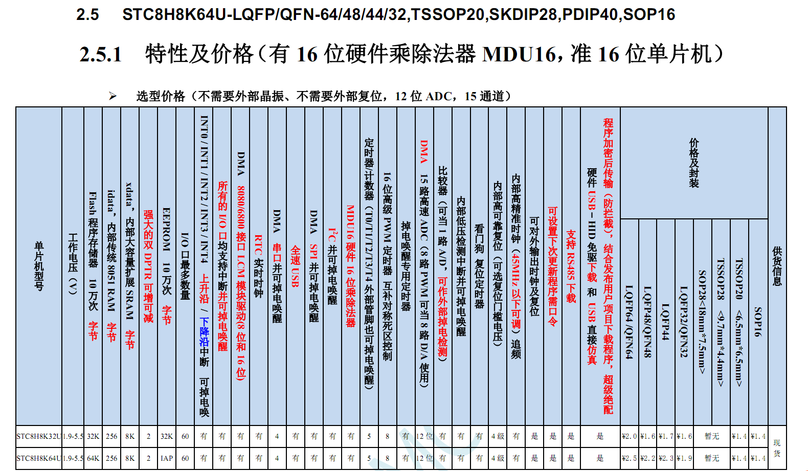
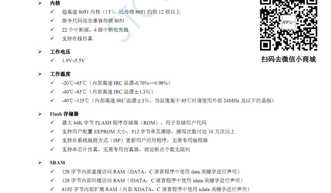
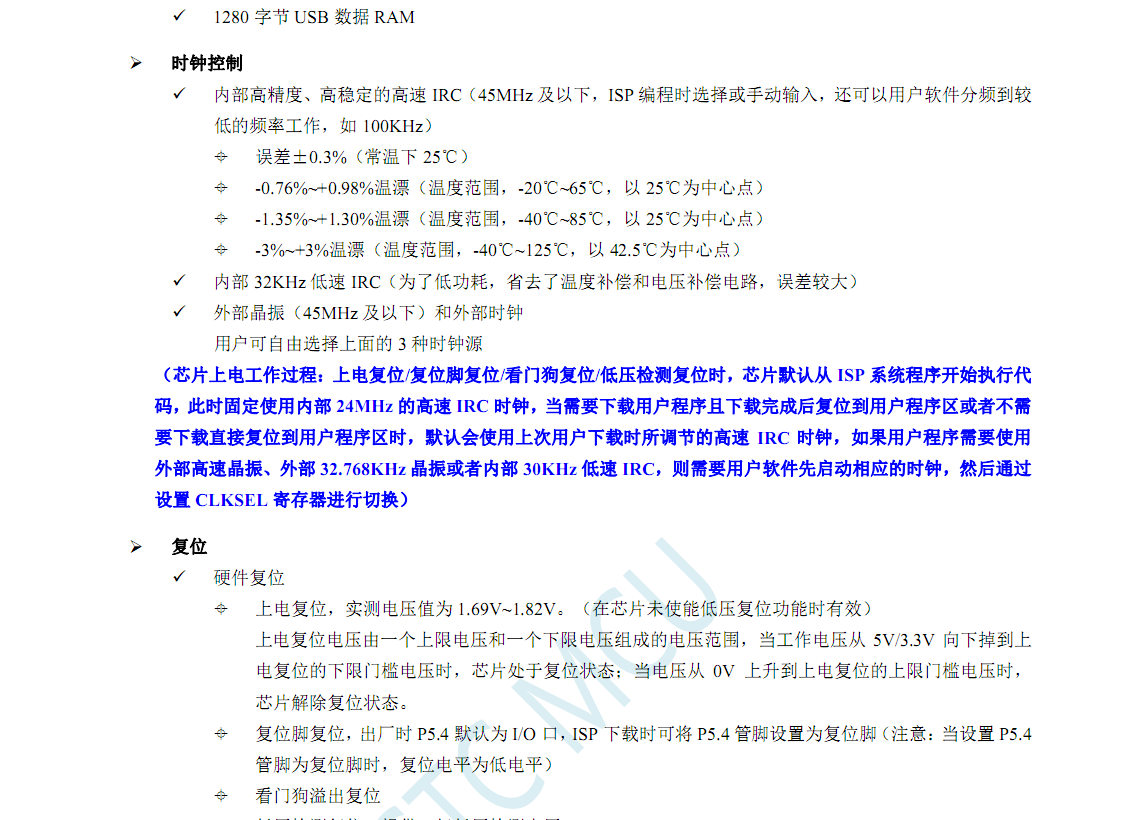
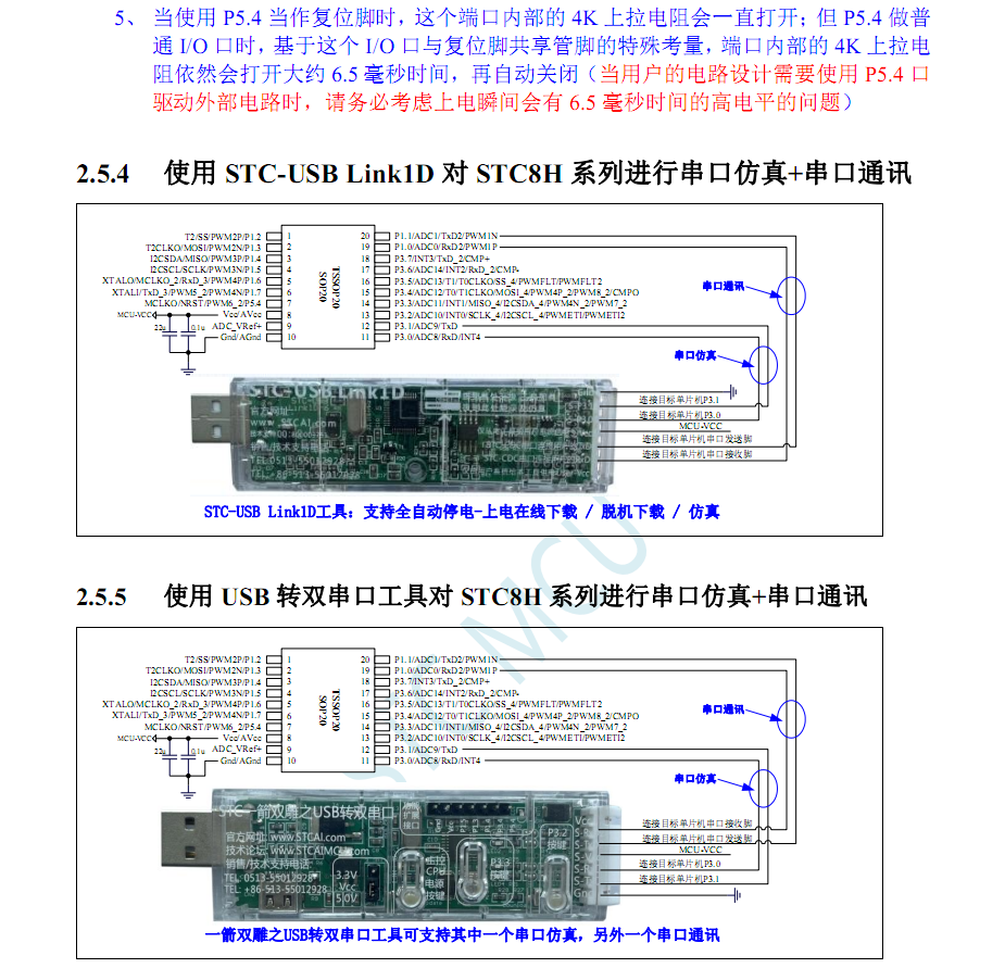
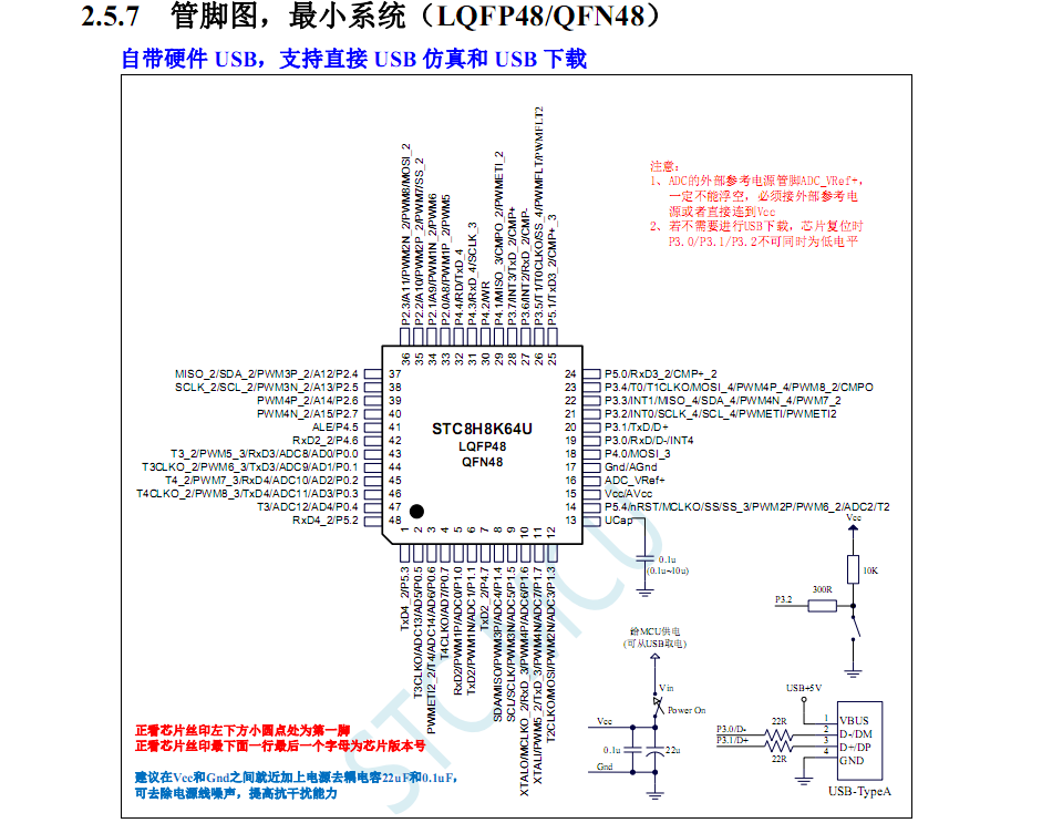
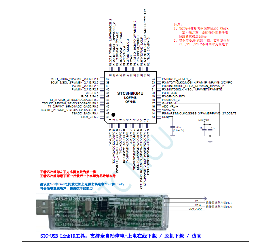
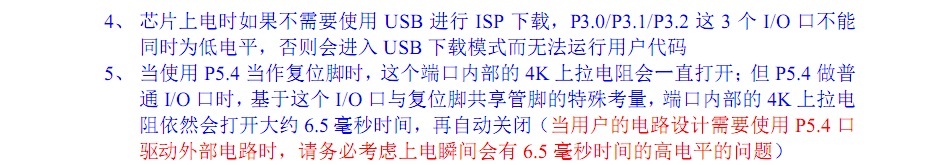
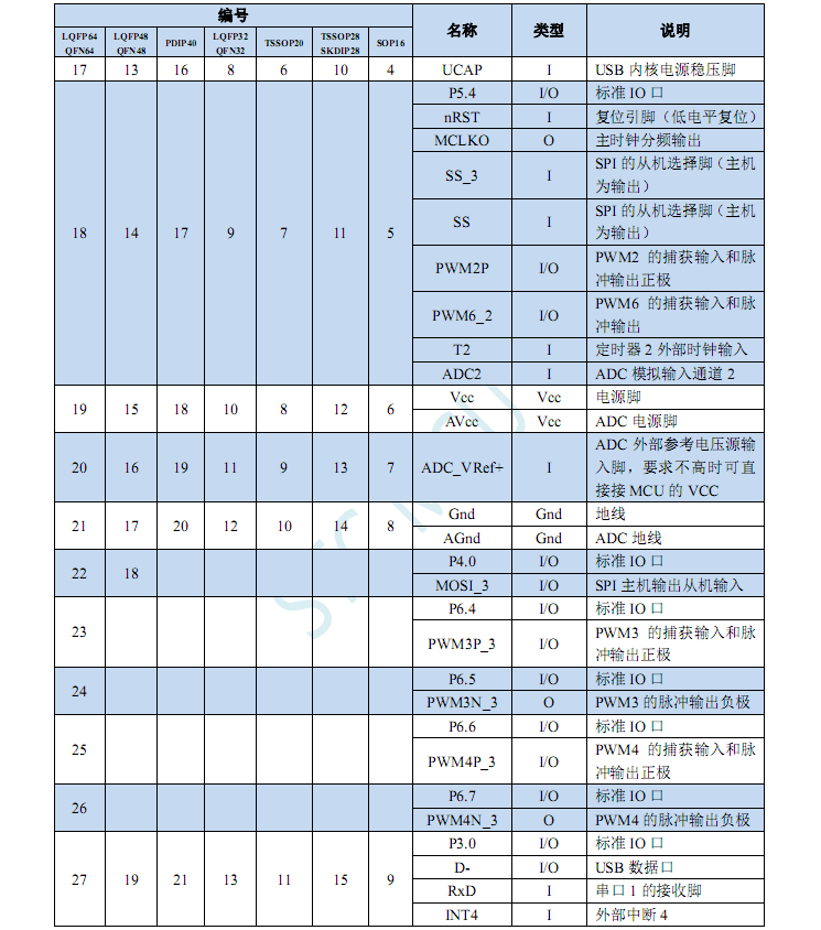
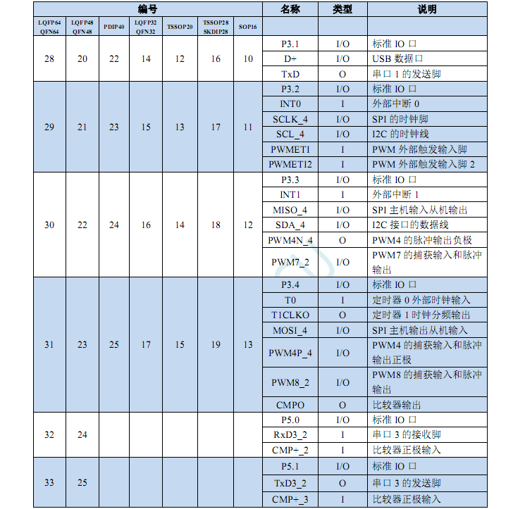
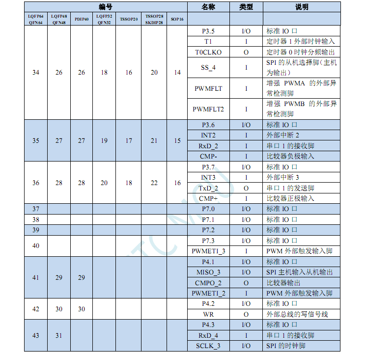
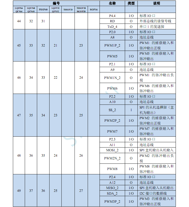
microcontroller for the STC8H8K64U minimum system board . The development board track allows participants to design a development board based on the following recommended chips. The project track requires participants to design a complete electronic product project using officially recommended chips. Officially recommended chips include: STC32G12K128-LQFP64, LQFP48, LQFP44, LQFP32, PDIP40, and STC8H8K64U-LQFP64 , LQFP48, LQFP44, LQFP32, and PDIP40. Participants must complete the schematic and PCB design, fill out the coupon form, and submit it for review. Once approved, the coupon can be claimed! ——————————————— Activity Process View: https://lceda002.feishu.cn/docx/K1e9dhpFBolmlyxNivncHNKinLh Technical Guidance: https://www.stcaimcu.com/forum.php?mod=forumdisplay&fid=90 STC Video Tutorials/Claim Experiment Kits and Other Gifts: https://www.stcaimcu.com/forum.php?mod=viewthread&tid=3184&extra=&page=1 【Open Source Project Completion】Those who have completed the physical prototype should initiate the open source project completion as soon as possible. This requires changing the cover to a physical verification image, selecting an open source license , adding a project description and open source description (explaining the functionalities and design concepts of this work), and adding a demonstration video and physical verification image to the open source description. If the open source review fails, you can directly contact 【Activity Sauce】 to inquire about the relevant reasons. Time: June 17, 2024 - July 31, 2024 ## The schematic design is based on the manual !!! Note!!! My schematic is slightly different from the official one. Those who need it can view it directly in the attachment. It uses a resettable fuse for power-on safety protection. Although STC is high-voltage, domestic LDO is awesome. It uses a low-dropout chip and directly uses Type-C to download the program. PCB design instructions reduce vias and reduce the impact on the signal. At the same time, the signal lines of the crystal oscillator are guaranteed to be of equal length. The original Type-C package is relatively short and has been lengthened for easy soldering. My drawing may be larger than others, mainly for the convenience of drawing and soldering. The white label box is directly used to fill in which one (it is reused quite a lot). First version Second version Software instructions Here, the smallest board designed is used to light the breathing light. **Code block:** /*---------------------------------------------------------------------*/ /* --- STC MCU Limited ------------------------------------------------*/ /* --- STC 1T Series MCU Demo Programme -------------------------------*/ /* --- Mobile: (86)13922805190 ----------------------------------------*/ /* --- Fax: 86-0513-55012956,55012947,55012969 ------------------------*/ /* --- Tel: 86-0513-55012928,55012929,55012966 ------------------------*/ /* --- Web: www.STCAI.com ---------------------------------------------*/ /* --- BBS: www.STCAIMCU.com -----------------------------------------*/ /* --- QQ: 800003751 -------------------------------------------------*/ /* If you want to use this code in your program, please indicate that you used STC materials and programs. */ /*---------------------------------------------------------------------*/ #include "stc8h.h" //After including this header file, you do not need to include the "reg51.h" header file. #define MAIN_Fosc 24000000L //Define the master clock /************* Functional Description ************** This example program is written and tested based on an experimental box using the STC8H8K64U as the main control chip. STC8G and STC8H series chips can be used as a general reference. The program uses the P6 port to demonstrate a running light effect with low-drive output. When the user performs ISP download to the STC8H8K64U series via hardware USB, the internal IRC frequency cannot be adjusted, but the user can select from 16 preset frequencies (5.5296M, 6M, 11.0592M, 12M, 18.432M, 20M, 22.1184M, 24M, 27M, 30M, 33.1776M, 35M, 36.864M, 40M, 44.2368M, and 48M). During download, the user can only select one frequency from the drop-down list and cannot manually input other frequencies. (For serial port downloading, any frequency between 4MHz and 48MHz can be input). During download, select clock 24MHz (users can modify the frequency themselves). ******************************************/


typedef unsigned char u8;
typedef unsigned int u16;
typedef unsigned long u32;
u8 ledIndex;
u8 code ledNum[]={0x01,0x02,0x04,0x08,0x10,0x20,0x40,0x80};
void delay_ms(u8 ms);
/******************** Main function **************************/
void main(void)
{
P_SW2 |= 0x80; // Enable access to extended registers (XFR)
P0M1 = 0x30; P0M0 = 0x30; // Set P0.4 and P0.5 to open drain (pull-up resistors were added to 3.3V in the experimental box)
P1M1 = 0x30; P1M0 = 0x30; //Set P1.4 and P1.5 to open drain (pull-up resistors added to 3.3V in the experimental setup)
P2M1 = 0x3c; P2M0 = 0x3c; //Set P2.2~P2.5 to open drain (pull-up resistors added to 3.3V in the experimental setup)
P3M1 = 0x50; P3M0 = 0x50; //Set P3.4 and P3.6 to open drain (pull-up resistors added to 3.3V in the experimental setup)
P4M1 = 0x3c; P4M0 = 0x3c; //Set P4.2~P4.5 to open drain (pull-up resistors added to 3.3V in the experimental setup)
P5M1 = 0x0c; P5M0 = 0x0c; //Set P5.2 and P5.3 to open drain (pull-up resistors added to 3.3V in the experimental setup)
P6M1 = 0x00; P6M0 = 0xff; // Set to push-pull output
P7M1 = 0x00; P7M0 = 0x00; // Set to quasi-bidirectional port
P40 = 0; // LED Power On
ledIndex = 0;
while(1)
{
P6 = ~ledNum[ledIndex]; // Output low drive
ledIndex++;
if(ledIndex > 7)
{
ledIndex = 0;
}
delay_ms(250); delay_ms(250 )
;
}
}
// = ... // Parameter: ms, the number of milliseconds to delay. Only 1~255ms is supported here. Automatically adapts to the master clock. // Return: none. // Version: VER1.0 // Date: 2021-3-9 // Remarks: //====================================================================== void delay_ms(u8 ms) { u16 i; do{ i = MAIN_Fosc / 10000; while(--i); //10T per loop }while(--ms); Physical demonstration and instructions: Before soldering (apply solder paste and heat; use tweezers to evenly distribute the solder paste, ensuring each pad has solder). After soldering (place the component on the heat pad and use tweezers to hold it in place). Precautions: Chips have many pins; be careful not to bridging, short-circuiting, or open-circuiting during soldering. If possible, use flux on a hot plate or a good soldering iron. [Linux Mobile Phone Soldering and Debugging] LCSC Taishanpai RK3566 Linux Development Board Training Camp Lesson 9: https://www.bilibili.com/video/BV19i421y7Hv?vd_source=a24af399230363e07c9d193ed6dde36a [Summary Series] Soldering Techniques! [13 Lectures to Teach Circuit Soldering from Scratch] https://www.bilibili.com/video/BV1xV411r7YY?vd_source=a24af399230363e07c9d193ed6dde36a [Complete Process of Manual Soldering a 100-Pin Chip] https://www.bilibili.com/video/BV1r64y1V7or?vd_source=a24af399230363e07c9d193ed6dde36a [Taobao] https://m.tb.cn/h.g7qAJhN8JmHleFL?tk=XNgG3YQYpxy CZ0000 "Deer Fairy Heating Board LED Bead Desoldering Station LCD Light Strip Desoldering Preheating Station BGA Chip Repair Heating Board" [Taobao] https://m.tb.cn/h.girHQQumhV8Bvay?tk=KMHP3YQ1psK CZ0001 "OLK Chip Mobile Phone Repair Solder Paste Lead-Free Medium High Low Temperature Solder Paste Solder Slurry Chip Soldering Syringe" Chip Information (Note) Download Process ....... Project cost is zero (purpose is learning) [ ] Chips are redeemed with points from the STC official website [ ] Other materials were previously purchased from LCSC Mall


[ ] The board is a free sample from JLCPCB.
In my schematic, I indicated one point and one line, but I selected the entire network. After consulting with official support, I found that I only needed to uncheck the network in the filter bar on the right. When downloading
programming

via USB, you need to ground P3.2 and then power on again (it is recommended to use a switch) (regardless of whether it has been powered on before). Until the following image is displayed, it means you have successfully entered the download mode. If

you haven't entered, the following image will be displayed.
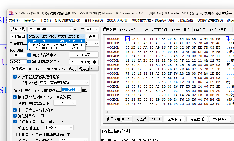
See
the attached video below (breathing light).
The file is in the hex file (P2.5 is connected to the cathode of a regular LED, and the anode is connected to 3.3V).
Finally
, thank you JLCPCB and
STC
. (It would be even better if there was an experimental box [doge])
STC8H8K64U Experimental Box - V9.6 Instruction Manual.pdf
STC8H-20240613.pdf
STC8G-STC8H-LIB-DEMO-CODE-20240429.zip
STC8G-8H Library Function Usage Instructions - 20240429.pdf
stcai-isp-v6.94H.zip
d7ca1cb1c22144913485d5d75df17059.mp4
led.hex
STC8H8K64U-DEMO-CODE-V9.6-20240418.zip
PDF_STC8H8K64U Minimum System Board Microcontroller Design.zip
Altium_STC8H8K64U Minimum System Board Microcontroller Design.zip
PADS_STC8H8K64U Minimum System Board Microcontroller Design.zip
BOM_STC8H8K64U Minimum System Board Microcontroller Design.xlsx
93739
electronic


 京公网安备 11010802033920号

 HS28JA-2B


