Design Background: ADCs (Analog-to-Digital Converters) are indispensable key components in electronic systems. They convert continuous analog signals into digital signals, enabling digital processing and analysis. ADCs play a crucial role in signal conversion, measurement and data acquisition, control system input, and communication and signal processing. Their widespread application promotes the intelligent and precise control of electronic equipment across various industries, and is one of the key factors driving modern technological progress. Digital voltmeters and ammeters combine ADC technology with circuit measurement principles, accurately converting analog voltage and current signals into digital displays for easy reading and analysis by electronic engineers. This device not only improves the accuracy and efficiency of circuit measurements but also helps engineers better understand circuit behavior, serving as a powerful tool for electronic design and troubleshooting, and playing a vital supporting role in the work of electronic engineers. In product applications, digital voltmeters ensure the accuracy and safety of circuit design, while also providing strong support for product quality control and subsequent maintenance. The key advantages of the CW32
, superior anti-interference capabilities (HBM ESD 8KV, all ESD reliability meets the highest international standard (STM32 ESD 2KV))
, and a superior ADC (12-bit high-speed ADC with ±1.0LSB INL 11.3ENOB), multiple Vref reference voltages (STM32 only supports VDD=Vref), and
stable and reliable eFLASH technology. (Schematic and PCB
Thanks to JLCPCB's LCPCB training camp for giving me this opportunity to learn about
the oscilloscope project.
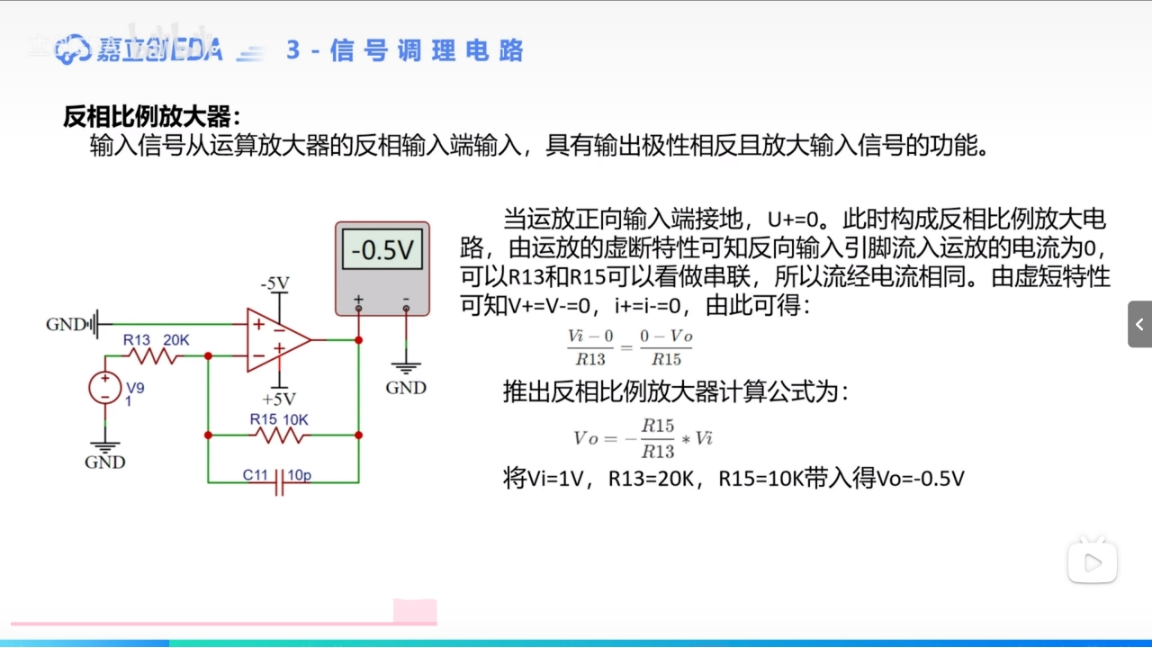
Inverting Amplification Analysis:
When the voltage comparator IN+ > IN-, the output is VCC.
When the inverting amplifier IN is 1V, because IN- > IN+, the output is the maximum negative voltage. The output is fed back to IN- through R2 (R1 and R2 divide the voltage, R2 is 2/3 of VCC, the output is fed back to IN- through R2, which is equivalent to a pull-down, IN to R1 is equivalent to a pull-up). The IN- voltage is pulled low.
When IN- is less than GND, the output OUT is VCC. At this time, OUT and R2 form a pull-up, and IN- is pulled up again.
This process is repeated until the op-amp is stable.
When IN+ > IN-, OUT = VCC, OUT pulls up IN- through R2.
IN+
repeats until the op-amp is in steady state, IN+ = IN-; //This is the concept of virtual open circuit
(the return resistor is connected to the negative terminal, which is negative feedback).
In fact, it fixes the voltage difference between the inverting and non-inverting input terminals within a very small range, so that the amplifier works in the linear operating region, reducing the amplification factor A, which is no longer infinite.
I1 = I2 = IN/R1; Based on the virtual short circuit IN-=IN+ being GND,
Vout=(IN-) -V2=0v-IN/R1*R2; =-R2/R1*IN (amplification factor) // Adjusting R1 and R2 can change the amplification factor
and IN to 1v, OUT to -2v; Note that if the output is ±12V, the power supply must also be ±12V (dual power supply).


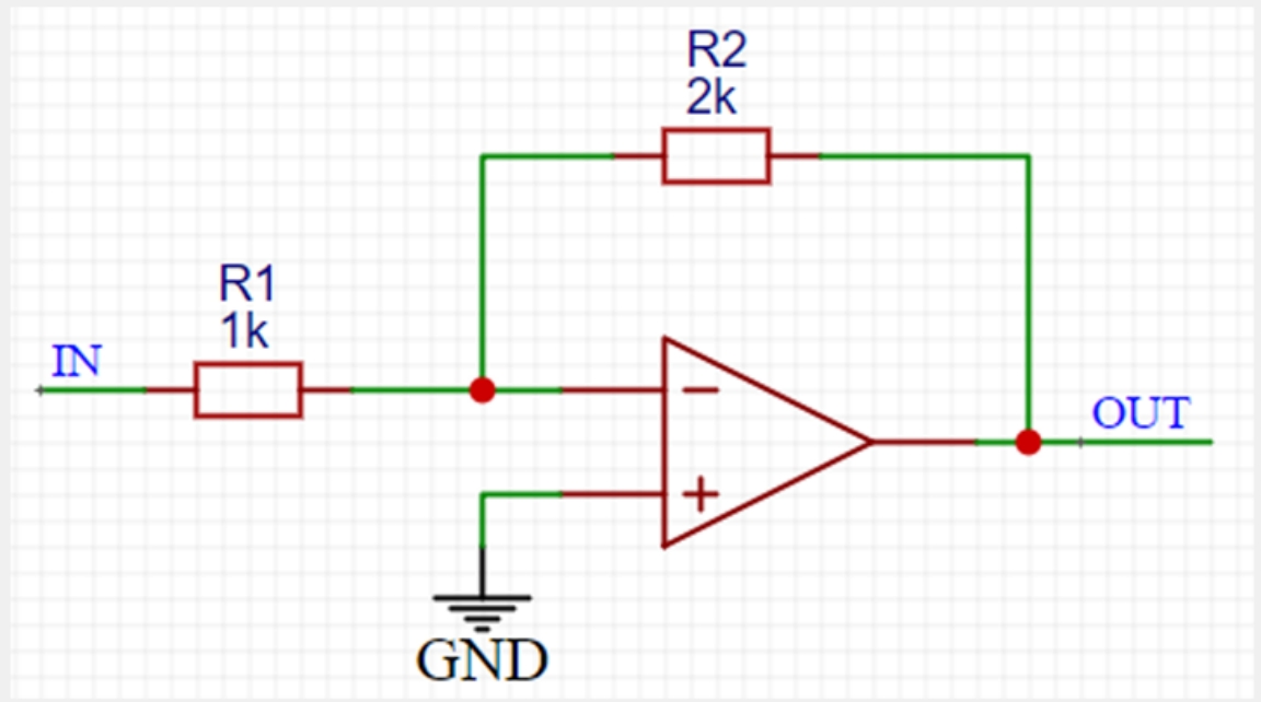
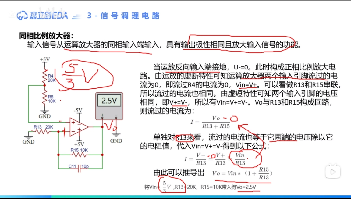
In-phase amplification analysis:
IN=IN+=IN-
, so I1 flows from R1 to GND. Due to the virtual short circuit characteristic of the op-amp, I1 will not flow into or out of the op-amp, so the current can only flow out from OUT.
I1=I2 =IN/R1, U2=I1*R2.
Vout=IN+U2=IN+IN/R1*R2
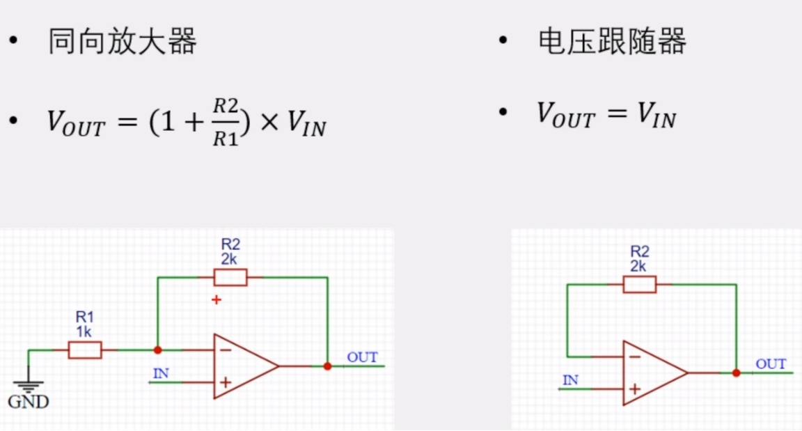
=(1+R2/R1)*IN.
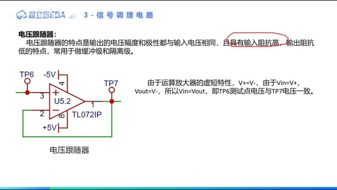
Voltage follower analysis:
Vout=(1+R2/R1)*IN.
R1 is infinite.
Vout=(1)*IN
input connected to IN+ is positive amplification
input connected to IN- is negative amplification
When analyzing, the input can be assumed to be 0; or the analysis can start from the ground terminal.
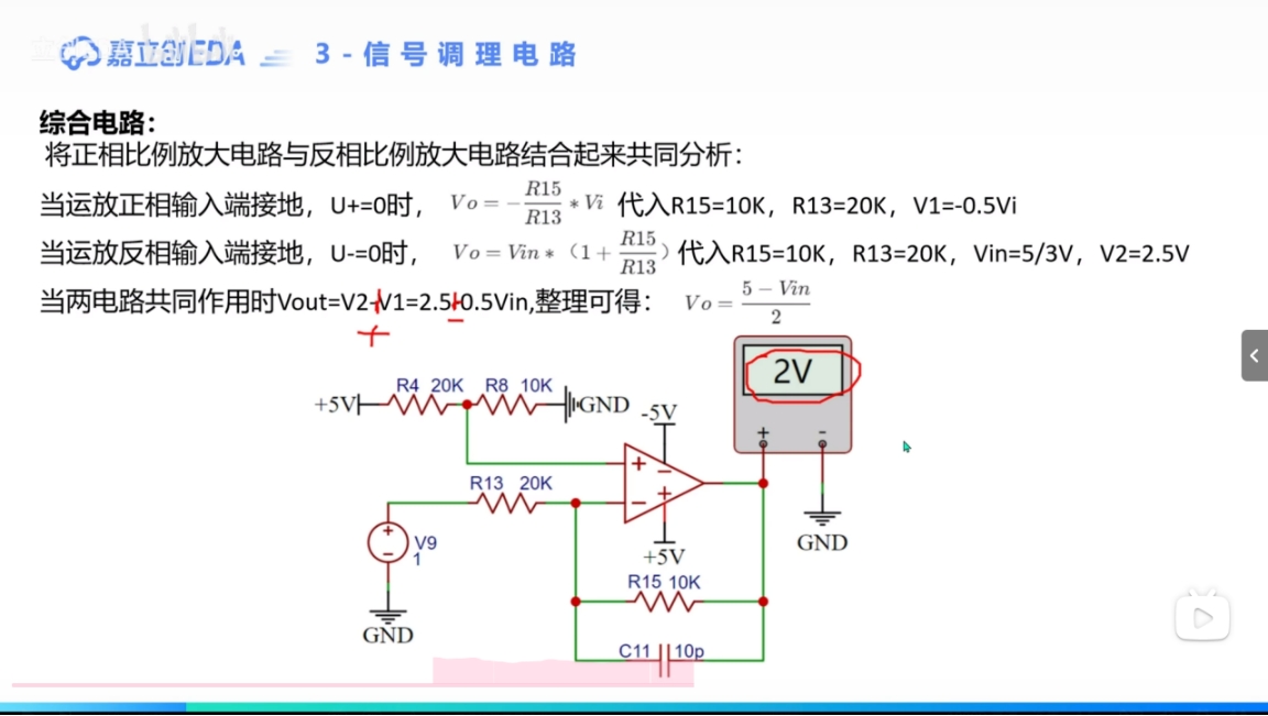
Because it is assumed that the circuit satisfies the ohmic characteristic, the two power supplies can be regarded as independent ideal power supplies. Here, the circuit can be divided into a reverse circuit and a forward circuit for analysis. Finally, the two analysis results are added in the agreed direction to obtain the final result.
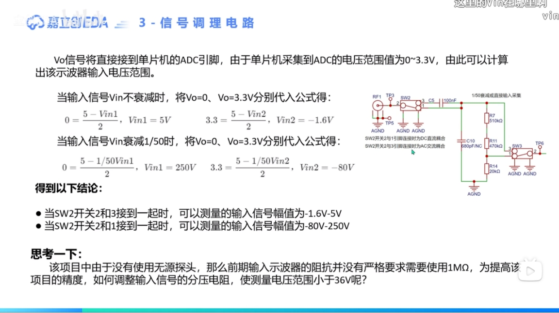
When the voltage division ratio is 35:1 680k+2k—20k
165~-56
When the voltage division ratio is 30:1
150~-48
When the voltage division ratio is 5:1 750k~39+11k
25~-8
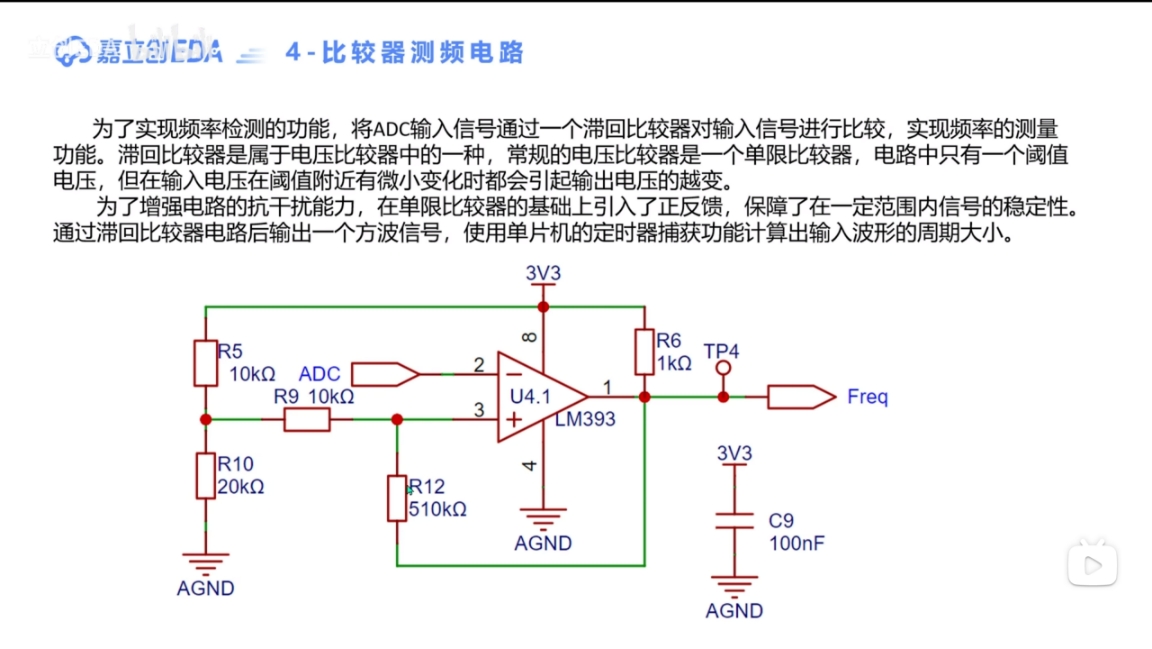
Single limit comparator
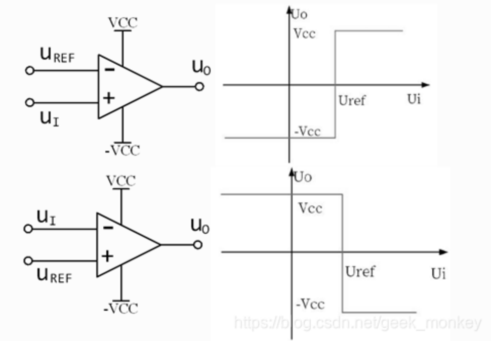
Generally speaking, the comparator only outputs high and low levels. If the op-amp is used as a comparator, it does not need to work in the linear region. Because operational amplifiers (op-amps) have very high amplification, if the voltage at the non-inverting input is slightly larger than the voltage at the inverting input, the op-amp will output its maximum voltage. For rail-to-rail op-amps, this maximum voltage will be close to the supply voltage Vcc. Conversely, if the voltage at the inverting input is larger than the non-inverting input, the op-amp will output its minimum voltage. If the supply voltage includes a negative voltage, the minimum voltage will be -Vcc; otherwise, it will be 0. Some circuits add output voltage limits, restricting the maximum and minimum values to specific values. For ease of description, this section will use Vcc for the maximum output voltage and -Vcc for the minimum output voltage.
We can connect one input to a reference voltage U_REF and the other to the voltage to be measured u_I to compare the magnitudes of the reference voltage and the voltage to be measured. The reference voltage is the threshold at which the output voltage transitions from high to low, or from low to high. This circuit has only one threshold voltage and is called a single-threshold comparator.
In
a hysteresis comparator, any tiny change in the input voltage near the threshold voltage will cause a jump in the output voltage, regardless of whether this tiny change originates from the input voltage or external interference. Therefore, although a single-threshold comparator is very sensitive, its noise immunity is poor. Adding positive feedback to a single-threshold comparator and connecting the inverting input to the input voltage creates a hysteresis comparator. It has inertia, appears to react relatively "slowly," is insensitive to tiny changes, and has some noise immunity; hence the name hysteresis comparator.
When an operational amplifier (op-amp) is used as a hysteresis comparator, it can be seen that without negative feedback, the op-amp does not operate in the linear region. When the output voltage jumps, it passes through the linear region; the positive feedback speeds up the process. A comparator circuit containing positive feedback is also called a Schmitt trigger.
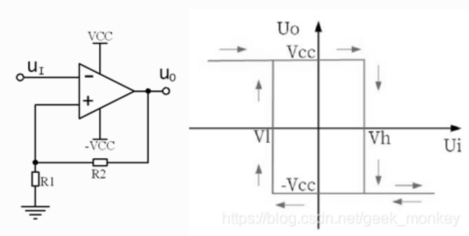
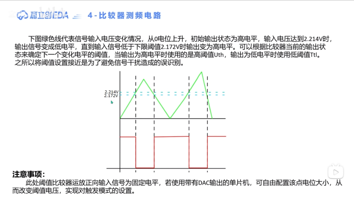
When analyzing the working principle of a hysteresis comparator, we can discuss different cases based on the magnitude of the input voltage:
1. When the input voltage u_I is very small, the output voltage u_O = Vcc. At this time, the voltage u_N at the non-inverting input terminal can be calculated using the resistor voltage divider formula.
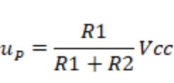
For ease of description, we let vh equal this formula.
2. As the input voltage u_I gradually increases, but is still less than v_h, since the non-inverting input terminal of the op-amp is always greater than the inverting input terminal, the output voltage u_O remains equal to Vcc.
3. When the input voltage u_I continues to increase and momentarily exceeds v_h, since the non-inverting input terminal of the op-amp is less than the inverting input terminal, the output voltage u_O becomes its minimum value -Vcc. After this, even if u_I continues to increase, the output voltage remains unchanged.
At this point, the voltage at the non-inverting input terminal can be calculated:
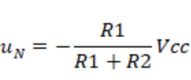
For ease of description, we let vl equal this formula.
4. The input voltage u_I begins to decrease.
When u_I > v_h, u_O jumps; however
, if the input voltage u_I continues to decrease, at the instant it is slightly less than v_l, the voltage at the inverting input terminal is less than that at the non-inverting input terminal, so u_O becomes its maximum value. If we want u_O to return to its minimum value, u_I > v_h. That is, u_I fluctuates slightly around v_l without affecting the output.
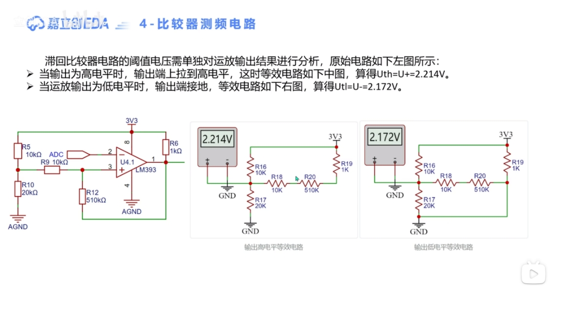
At the instant the output voltage is about to jump, the voltages at the non-inverting and inverting input terminals are exactly equal, so we can let u_P = u_N. The u_I calculated at this time is the threshold voltage. The v_h and v_l mentioned above are these two threshold voltages. Adjusting the values of resistors R1 and R2 can change the threshold voltage.
As can be seen from the voltage transfer characteristic curve, when the voltage
at the non-inverting input of the hysteresis comparator
with reference voltage v_l is changed from ground to a certain reference voltage U_REF, the two threshold voltages can be shifted to the left or right.

Let u_P = u_N, the threshold voltages can be calculated:
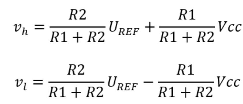
The above is a general formula for analyzing the threshold voltage of a hysteresis comparator. In practical applications, it may be simpler. R1, R2, and U_REF together determine the horizontal shift of the voltage transfer characteristic curve. If a negative power supply is not used, the "-R1/(R1+R2) Vcc" in v_l can be omitted.
A hysteresis comparator, also called a threshold comparator, is triggered
when the input exceeds a certain value, and is used in waveform detection

hardware circuit experiments.


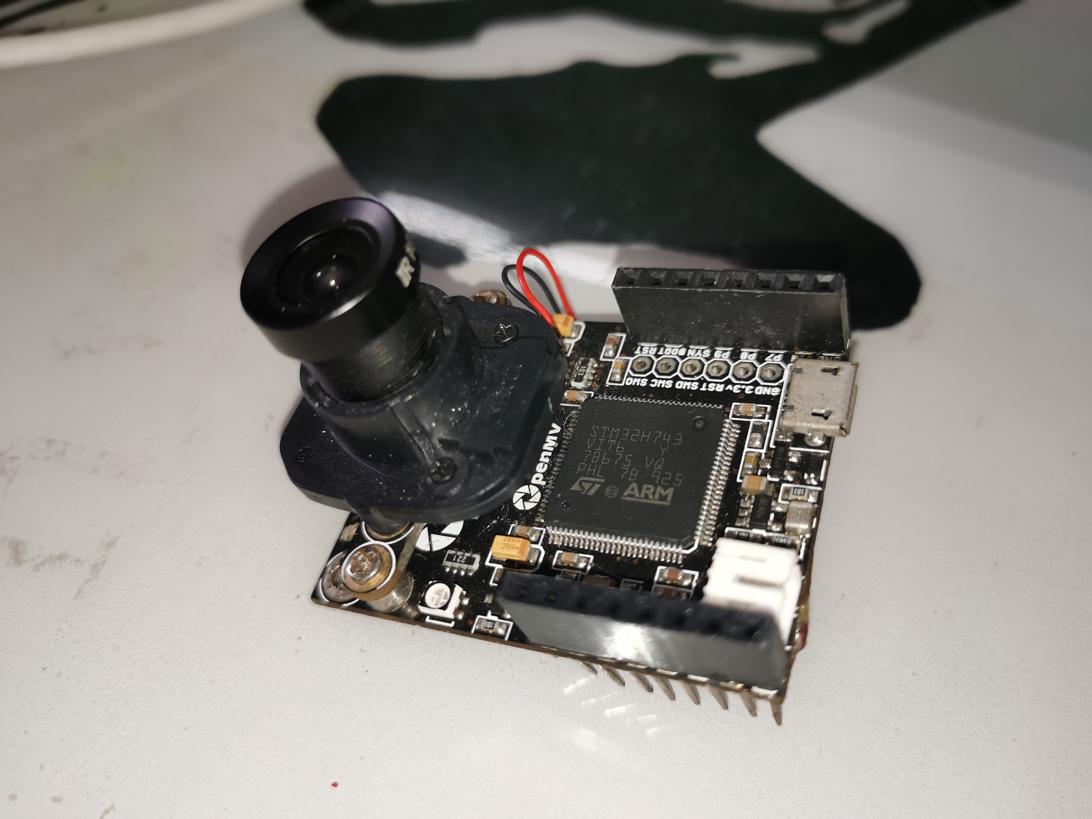
This project involves the PCB board of the discontinued OpenMV4 H7 R1 from StarEye Technology, intended for repair and replication.
The BOM (Bill of Materials) is incorrect!!!
The BOM is incorrect!!!
The BOM is incorrect!!! (
Important: I'm saying it three times! )
This file contains the official open-source PCB for the OpenMV4 R1 board. It can be used for replacing damaged pins and for replicating designs. Please do not use it for commercial purposes.
OpenMV4 H7R1 schematic diagram.pdf
PDF_Discontinued XingTong Technology OpenMV4 H7 R1.zip
Altium (discontinued) OpenMV4 H7 R1.zip
PADS_Discontinued StarEye Technology OpenMV4 H7 R1.zip
BOM_Discontinued StarEye Technology OpenMV4 H7 R1.xlsx
92929
CC Table - CW32
CC meter, without deception, displays voltage, current and power.
This document describes
the use of an LDO to power a microcontroller
, an INA226 as the voltage and current acquisition chip,
and an OLED screen for display.

Issues and subsequent optimizations
: 1. Using an LDO for power supply can easily cause system restarts when the USB-B voltage changes; a DC-DC converter is planned for the next version.
2. There was a bug in the OLED screen circuitry (now fixed).
3. A resistor divider network using the CW32's built-in ADC has been added for functional verification.
4. The overall current flowing through the board is relatively low; the power supply issue for the Type-C port still needs to be addressed.
5. Reserved buttons have been removed.
PDF_CC Table-CW32.zip
Altium_CC table-CW32.zip
PADS_CC table-CW32.zip
BOM_CC table - CW32.xlsx
92930
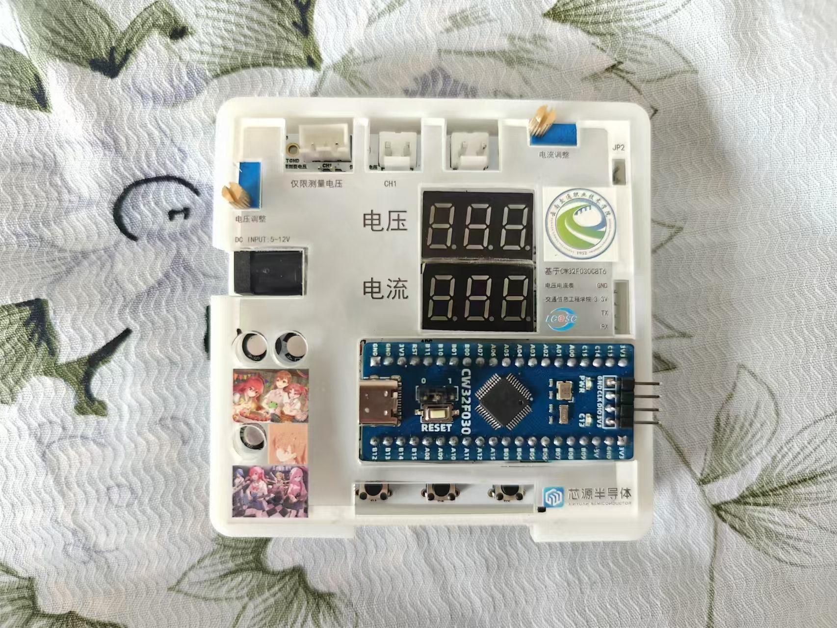
Voltage and current meter – based on CW32F030C8T6
LCSC GeoStar CW32 Digital Voltage and Current Meter Expansion Board
I. Hardware Design
1. Power Supply Circuit
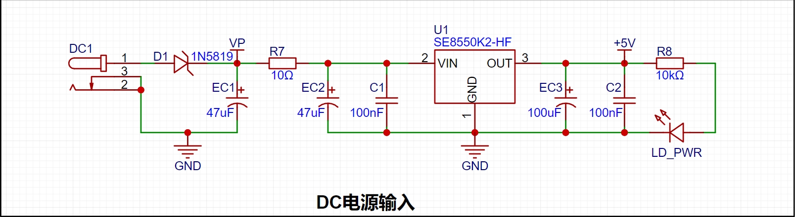
LDO (Low Dropout Linear Regulator) Selection This project uses an LDO as the power supply. Considering that most voltmeter products are used in industrial scenarios with 24V or 36V power supplies, the SE8550K2 with a maximum input voltage of up to 40V was selected as the power supply. The main reason for not using a DC-DC step-down circuit to handle the large voltage drop is to avoid introducing DC-DC ripple interference during the design process, and the secondary reason is to reduce project costs.
2. MCU Selection Analysis
To reduce the learning cost for everyone, this project uses the LCSC CW32F030C8Tx development board (core board) as the main controller, but this does not mean that we will talk less about this section. From the perspective of training engineers, the correct selection of the main controller is very important, as it relates to the overall advantage of the project. Regarding the voltmeter and current meter, the author used STM32/CW32 and some other 32-bit microcontrollers for some debugging and testing. This comparison is only with the STM32F103C8T6 as a reference for device selection, primarily aimed at providing ideas and improving understanding.
Avoid blind selection. When selecting an MCU (Microcontroller Unit) for this project, multiple aspects need to be considered to ensure the chosen MCU meets project requirements.
Clearly define your project needs: Understand the required computing power, including clock speed, processor core type, and whether a floating-point unit is needed.
Identify the required I/O ports and important peripherals, such as ADC peripherals. Since this is a development board project, primarily for debugging and learning, there are no strict limitations on the number of I/O ports: i.e., the associated costs are not considered.
Key advantages of the CW32 in this project
: Wide operating temperature range: -40~105℃;
Wide operating voltage range: 1.65V~5.5V (STM32 only supports 3.3V systems)
; Superior interference immunity: HBM ESD 8KV; All ESD reliability meets the highest international standard (STM32 ESD 2KV)
; Project focus - Better ADC: 12-bit high-speed ADC, achieving ±1.0LSB INL 11.3ENOB; Multiple Vref reference voltages... (STM32 only supports VDD=Vref);
Stable and reliable eFLASH technology.
A detailed explanation of these advantages will be provided in the chapters on ADC sampling and related extensions.
The main characteristics of the CW32 ADC: This project requires a focus on the 4 reference voltage sources. (Content from the "CW32x030 User Manual")
3. Voltage Sampling Circuit:
The voltage divider resistors in this project are designed to be 220K+10K, therefore the voltage division ratio is 22:1 (ADC_IN11).
The voltage divider resistor selection
is designed to measure the maximum voltage. For safety reasons, this project uses 30V (the actual maximum display value can be 99.9V or 100V).
The ADC reference voltage is 1.5V in this project, and this reference voltage can be configured through the program.
To reduce the power consumption of the sampling circuit, the low-side resistor (R7) is usually chosen as 10K based on experience.
Then, the high-side resistance of the voltage divider resistor can be calculated using the above parameters.
The required voltage division ratio is calculated, i.e., the ADC reference voltage. The input voltage is designed; using known parameters, 1.5V/30V = 0.05 can be calculated.
The high-side resistance is calculated as the low-side resistance/voltage division ratio; using known parameters, 10K/0.05 = 200K can be calculated.
A standard resistor is selected: a resistor slightly higher than the calculated value of 200K is chosen. We usually choose E24 series resistors; therefore, in this project, 220K, which is greater than 200K and closest to the calculated value, is selected.
If, in actual use, the voltage to be measured is lower than 2/3 of the module's design voltage (66V), the voltage divider resistor can be replaced and the program modified to improve measurement accuracy. The following example illustrates this:
Assuming the measured voltage is no higher than 24V and other parameters remain unchanged,
calculations show 1.5V/24V = 0.0625, 10K/0.0625 = 160K. 160K is a standard E24 resistor and can be directly selected, or a higher value 180K can be chosen with some redundancy.
If, in actual use, the voltage to be measured is higher than the module's 99V design voltage, a different resistor can be selected. To achieve a wider voltage measurement range, one can choose to replace the voltage divider resistor or modify the reference voltage. The following example illustrates this:
Assuming the measured voltage is 160V, the solution is to increase the voltage reference to expand the range.
Given that the voltage division ratio of the selected resistor is 0.0145, we can calculate 160V * 0.0145 = 2.32V using the formula. Therefore, we can choose a 2.5V voltage reference to expand the range (increasing the range will reduce accuracy).
Considering the potential fluctuations in the measured power supply, a 10nF filter capacitor is connected in parallel with the low-side voltage divider resistor to improve measurement stability.
Range switching:
In this project, an additional voltage sampling circuit was added. Therefore, we can discuss the significance of range switching for improving measurement accuracy. Multimeters often have multiple range settings for more accurate measurements. By adjusting different ranges, the optimal measurement accuracy of the measured point within the corresponding range can be obtained.
This project requires a combination of hardware and software to achieve this function. When we first use the ADC_IN11 channel mentioned earlier to measure voltages below 30V... If the measured voltage is within 0~3V, use the ADC_IN9 channel for measurement. In this case, the measurement accuracy is greatly improved due to the reduced voltage division ratio. There are many ways to implement gear shifting, and the development board design provides more design possibilities.
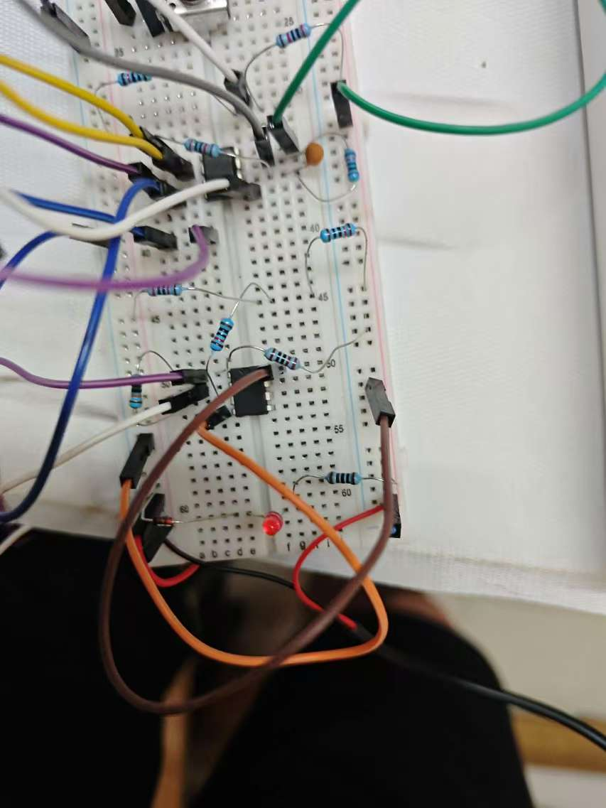
Physical diagram:
PDF_Voltmeter & Ammeter - Based on CW32F030C8T6.zip
Altium voltage and current meter - based on CW32F030C8T6.zip
PADS Voltage and Current Meter - Based on CW32F030C8T6.zip
BOM_Voltage and Current Meter - Based on CW32F030C8T6.xlsx
92931
electronic


 京公网安备 11010802033920号

 212Y0102S324MN5


