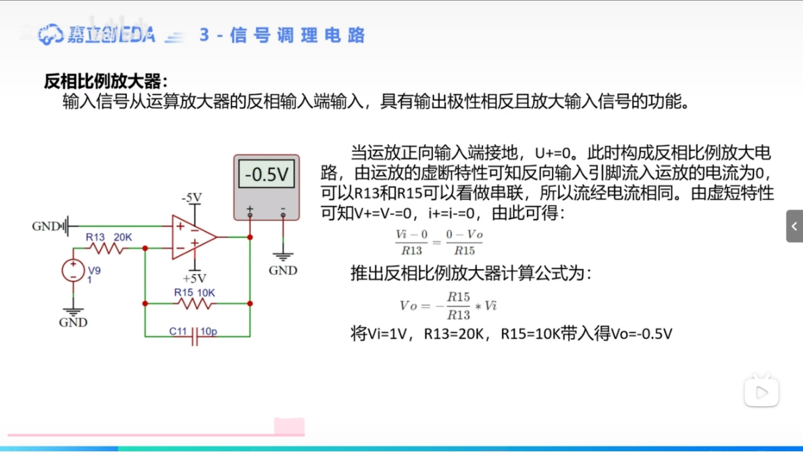
Inverting Amplification Analysis:
When the voltage comparator IN+ > IN-, the output is VCC.
When the inverting amplifier IN is 1V, because IN- > IN+, the output is the maximum negative voltage. The output is fed back to IN- through R2 (R1 and R2 divide the voltage, R2 is 2/3 of VCC, the output is fed back to IN- through R2, which is equivalent to a pull-down, IN to R1 is equivalent to a pull-up). The IN- voltage is pulled low.
When IN- is less than GND, the output OUT is VCC. At this time, OUT and R2 form a pull-up, and IN- is pulled up again.
This process is repeated until the op-amp is stable.
When IN+ > IN-, OUT = VCC, OUT pulls up IN- through R2.
IN+
repeats until the op-amp is in steady state, IN+ = IN-; //This is the concept of virtual open circuit
(the return resistor is connected to the negative terminal, which is negative feedback).
In fact, it fixes the voltage difference between the inverting and non-inverting input terminals within a very small range, so that the amplifier works in the linear operating region, reducing the amplification factor A, which is no longer infinite.
I1 = I2 = IN/R1; Based on the virtual short circuit IN-=IN+ being GND,
Vout=(IN-) -V2=0v-IN/R1*R2; =-R2/R1*IN (amplification factor) // Adjusting R1 and R2 can change the amplification factor
and IN to 1v, OUT to -2v; Note that if the output is ±12V, the power supply must also be ±12V (dual power supply).


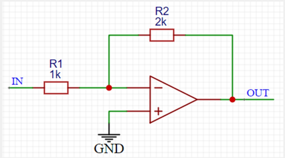
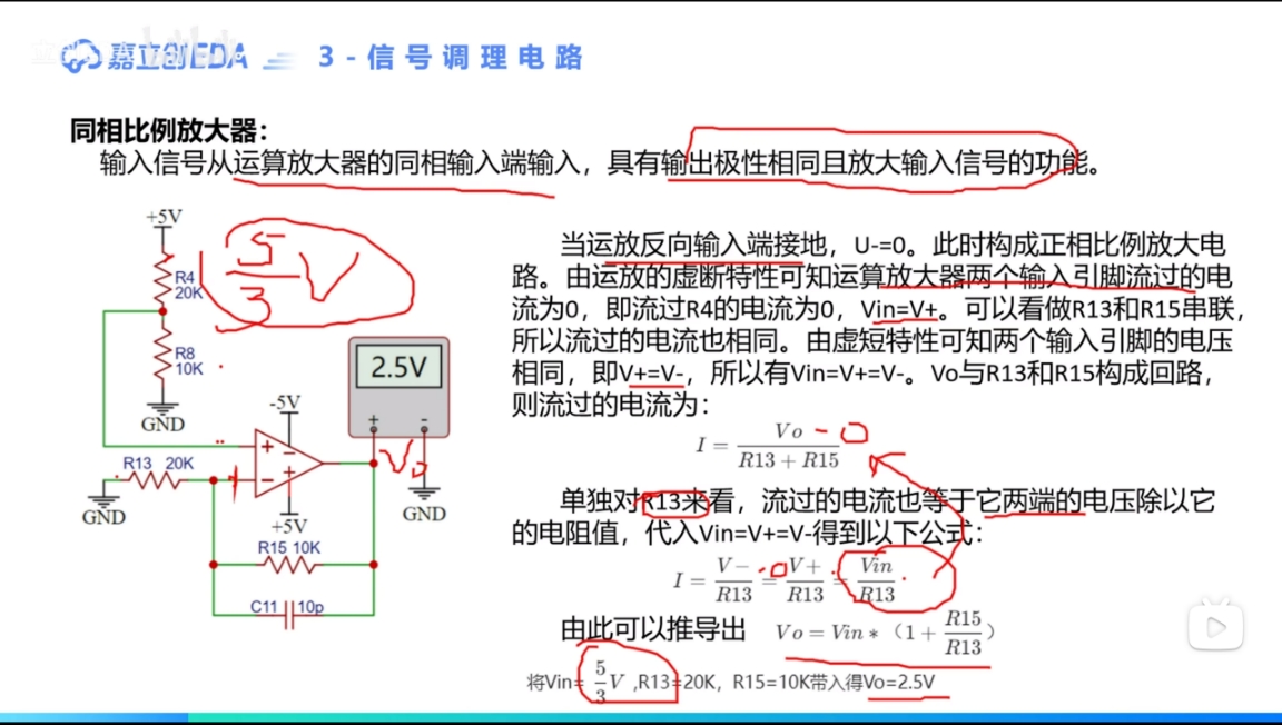
In-phase amplification analysis:
IN=IN+=IN-
, so I1 flows from R1 to GND. Due to the virtual short circuit characteristic of the op-amp, I1 will not flow into or out of the op-amp, so the current can only flow out from OUT.
I1=I2 =IN/R1, U2=I1*R2.
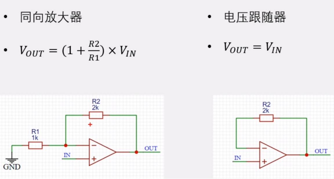
Vout=IN+U2=IN+IN/R1*R2
=(1+R2/R1)*IN.
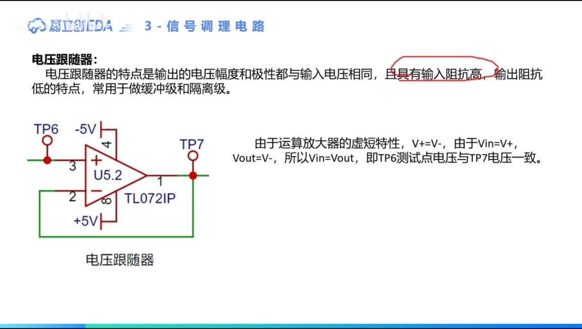
Voltage follower analysis:
Vout=(1+R2/R1)*IN.
R1 is infinite.
Vout=(1)*IN
input connected to IN+ is positive amplification
input connected to IN- is negative amplification
When analyzing, the input can be assumed to be 0; or the analysis can start from the ground terminal.
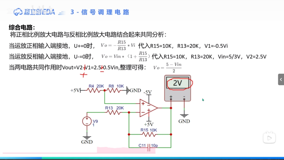
Because it is assumed that the circuit satisfies the ohmic characteristic, the two power supplies can be regarded as independent ideal power supplies. Here, the circuit can be divided into a reverse circuit and a forward circuit for analysis. Finally, the two analysis results are added in the agreed direction to obtain the final result.
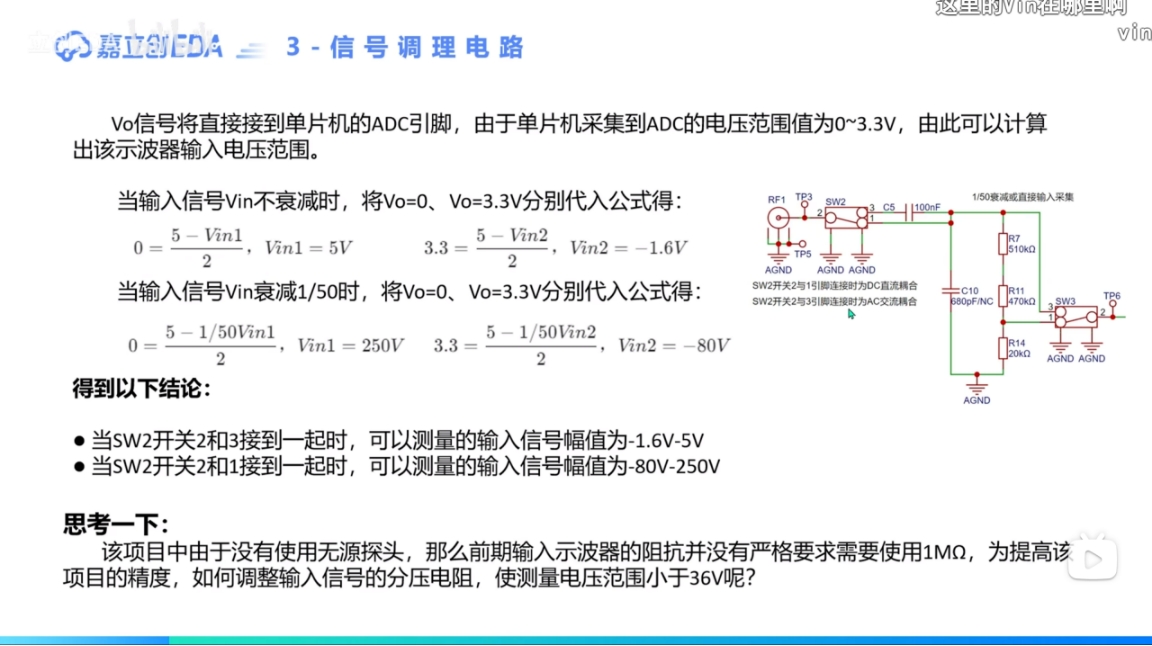
When the voltage division ratio is 35:1 680k+2k—20k
165~-56
When the voltage division ratio is 30:1
150~-48
When the voltage division ratio is 5:1 750k~39+11k
25~-8
Single limit comparator
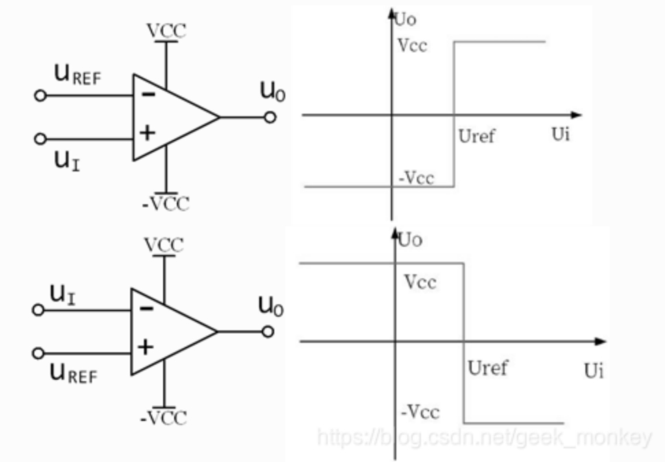
Generally speaking, the comparator only outputs high and low levels. If the op-amp is used as a comparator, it does not need to work in the linear region. Because operational amplifiers (op-amps) have very high amplification, if the voltage at the non-inverting input is slightly larger than the voltage at the inverting input, the op-amp will output its maximum voltage. For rail-to-rail op-amps, this maximum voltage will be close to the supply voltage Vcc. Conversely, if the voltage at the inverting input is larger than the non-inverting input, the op-amp will output its minimum voltage. If the supply voltage includes a negative voltage, the minimum voltage will be -Vcc; otherwise, it will be 0. Some circuits add output voltage limits, restricting the maximum and minimum values to specific values. For ease of description, this section will use Vcc for the maximum output voltage and -Vcc for the minimum output voltage.
We can connect one input to a reference voltage U_REF and the other to the voltage to be measured u_I to compare the magnitudes of the reference voltage and the voltage to be measured. The reference voltage is the threshold at which the output voltage transitions from high to low, or from low to high. This circuit has only one threshold voltage and is called a single-threshold comparator.
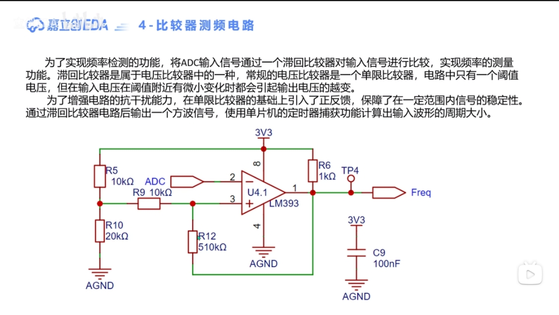
In
a hysteresis comparator, any tiny change in the input voltage near the threshold voltage will cause a jump in the output voltage, regardless of whether this tiny change originates from the input voltage or external interference. Therefore, although a single-threshold comparator is very sensitive, its noise immunity is poor. Adding positive feedback to a single-threshold comparator and connecting the inverting input to the input voltage creates a hysteresis comparator. It has inertia, appears to react relatively "slowly," is insensitive to tiny changes, and has some noise immunity; hence the name hysteresis comparator.
When an operational amplifier (op-amp) is used as a hysteresis comparator, it can be seen that without negative feedback, the op-amp does not operate in the linear region. When the output voltage jumps, it passes through the linear region; the positive feedback speeds up the process. A comparator circuit containing positive feedback is also called a Schmitt trigger.
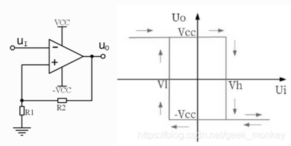
When analyzing the working principle of a hysteresis comparator, we can discuss different cases based on the magnitude of the input voltage:
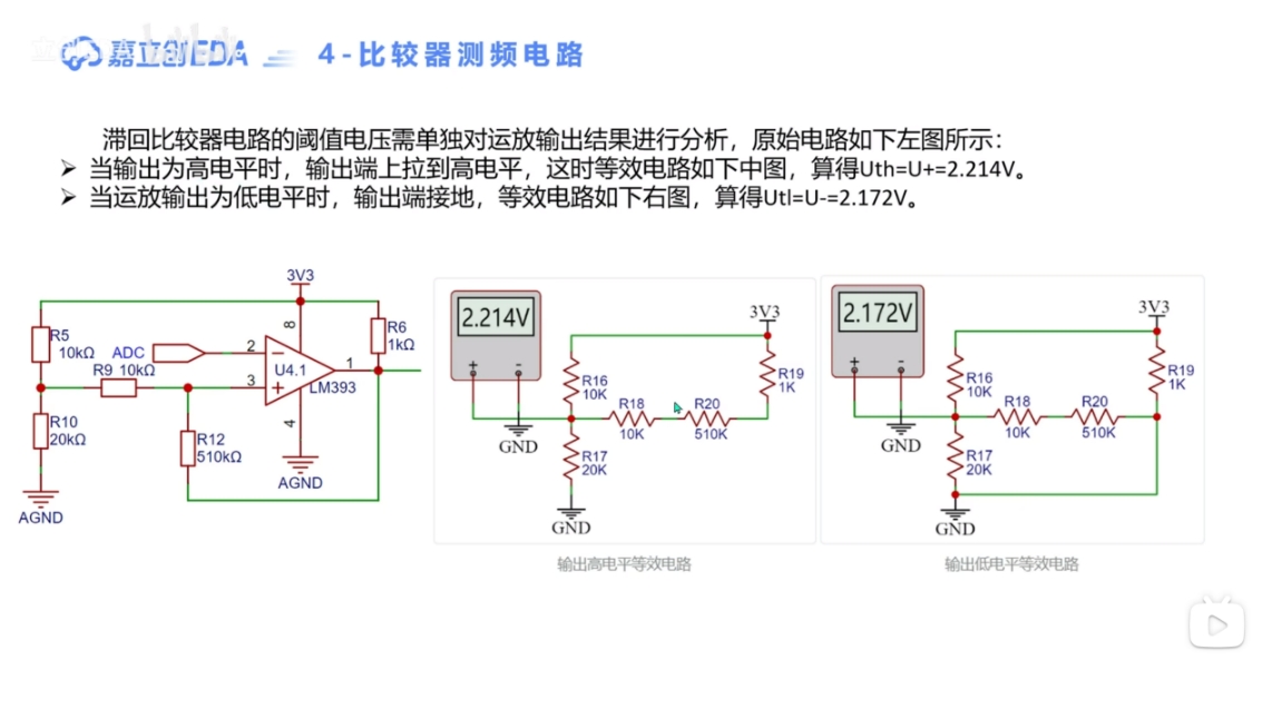
1. When the input voltage u_I is very small, the output voltage u_O = Vcc. At this time, the voltage u_N at the non-inverting input terminal can be calculated using the resistor voltage divider formula.
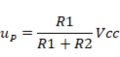
For ease of description, we let vh equal this formula.
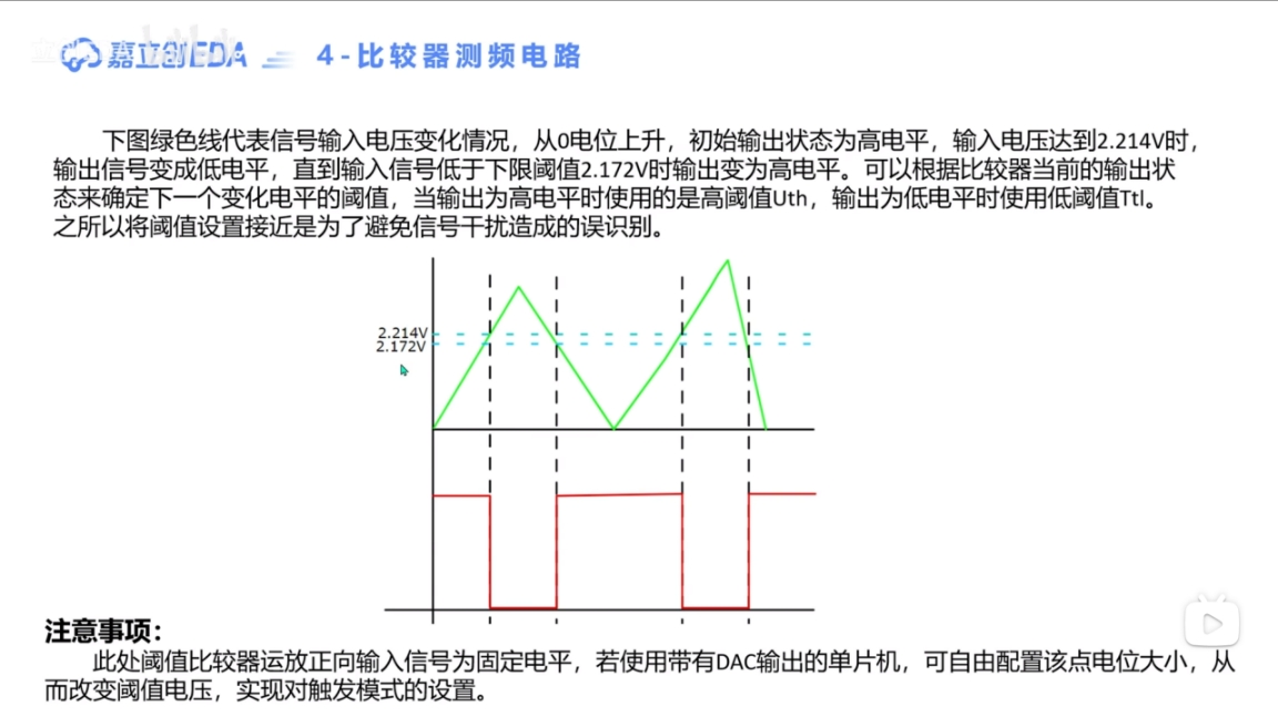
2. As the input voltage u_I gradually increases, but is still less than v_h, since the non-inverting input terminal of the op-amp is always greater than the inverting input terminal, the output voltage u_O remains equal to Vcc.
3. When the input voltage u_I continues to increase and momentarily exceeds v_h, since the non-inverting input terminal of the op-amp is less than the inverting input terminal, the output voltage u_O becomes its minimum value -Vcc. After this, even if u_I continues to increase, the output voltage remains unchanged.
At this point, the voltage at the non-inverting input terminal can be calculated:
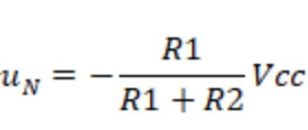
For ease of description, we let vl equal this formula.
4. The input voltage u_I begins to decrease.
When u_I > v_h, u_O jumps; however
, if the input voltage u_I continues to decrease, at the instant it is slightly less than v_l, the voltage at the inverting input terminal is less than that at the non-inverting input terminal, so u_O becomes its maximum value. If we want u_O to return to its minimum value, u_I > v_h. That is, u_I fluctuates slightly around v_l without affecting the output.
At the instant the output voltage is about to jump, the voltages at the non-inverting and inverting input terminals are exactly equal, so we can let u_P = u_N. The u_I calculated at this time is the threshold voltage. The v_h and v_l mentioned above are these two threshold voltages. Adjusting the values of resistors R1 and R2 can change the threshold voltage.
As can be seen from the voltage transfer characteristic curve, when the voltage
at the non-inverting input of the hysteresis comparator
with reference voltage v_l is changed from ground to a certain reference voltage U_REF, the two threshold voltages can be shifted to the left or right.

Let u_P = u_N, the threshold voltages can be calculated:
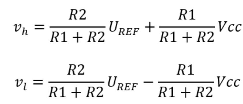
The above is a general formula for analyzing the threshold voltage of a hysteresis comparator. In practical applications, it may be simpler. R1, R2, and U_REF together determine the horizontal shift of the voltage transfer characteristic curve. If a negative power supply is not used, the "-R1/(R1+R2) Vcc" in v_l can be omitted.
A hysteresis comparator, also called a threshold comparator, is triggered
when the input exceeds a certain value, and is used in waveform detection

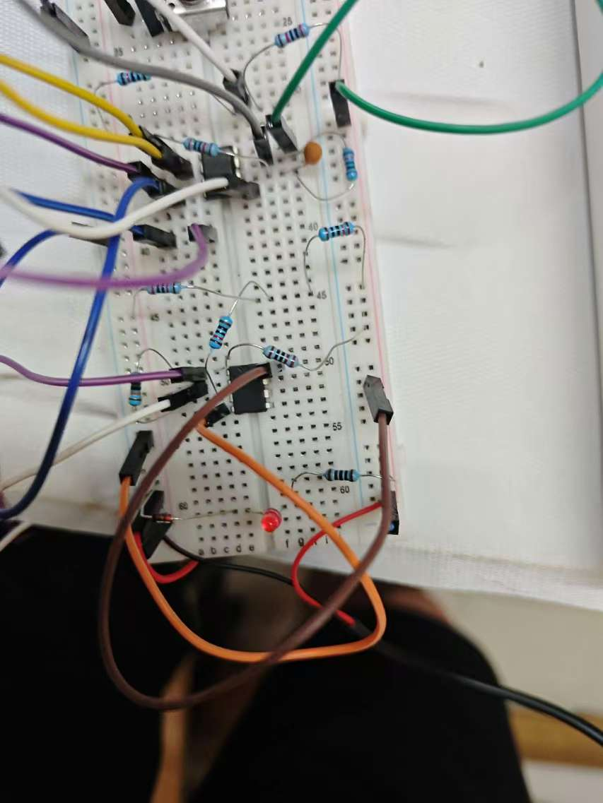
hardware circuit experiments.


 京公网安备 11010802033920号

 1N5925D


