I. Project Introduction
LCSC's Diwenxing is a development board designed using the Chipsource Semiconductor CW32, whose superior ADC (Analog-to-Digital Converter) performance makes it stand out in high-precision measurement applications. We used this development board to design a voltmeter and ammeter capable of simultaneously measuring voltages from 0-30V and currents from 0-3A, suitable for various electronic projects and laboratory environments.
II. Hardware Design
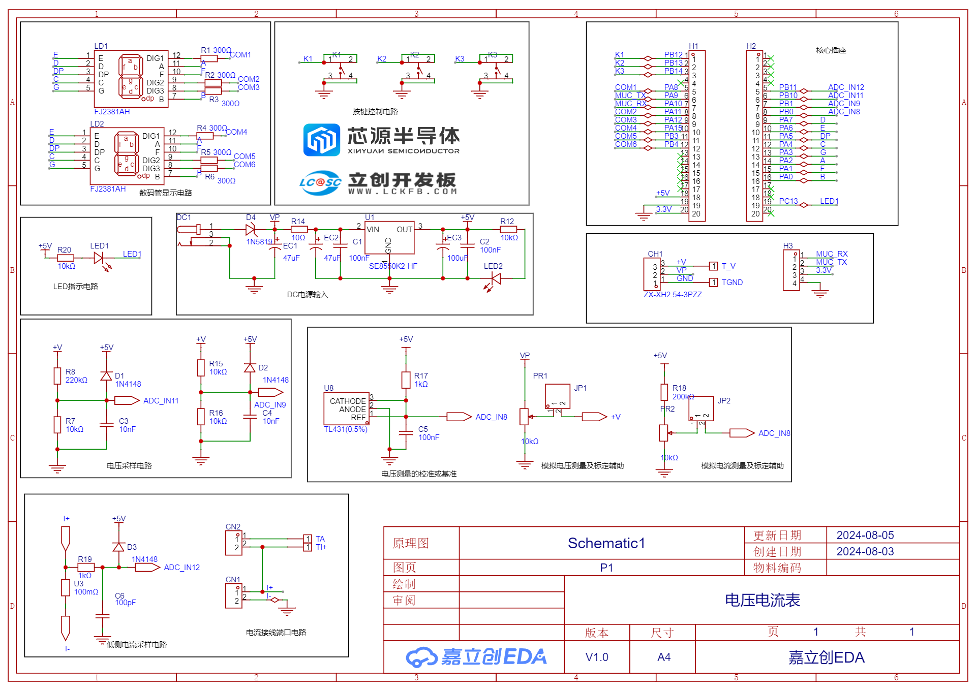
1. Project Schematic Diagram
![aa789dd3e14243e9bb0217822127296a.webp]
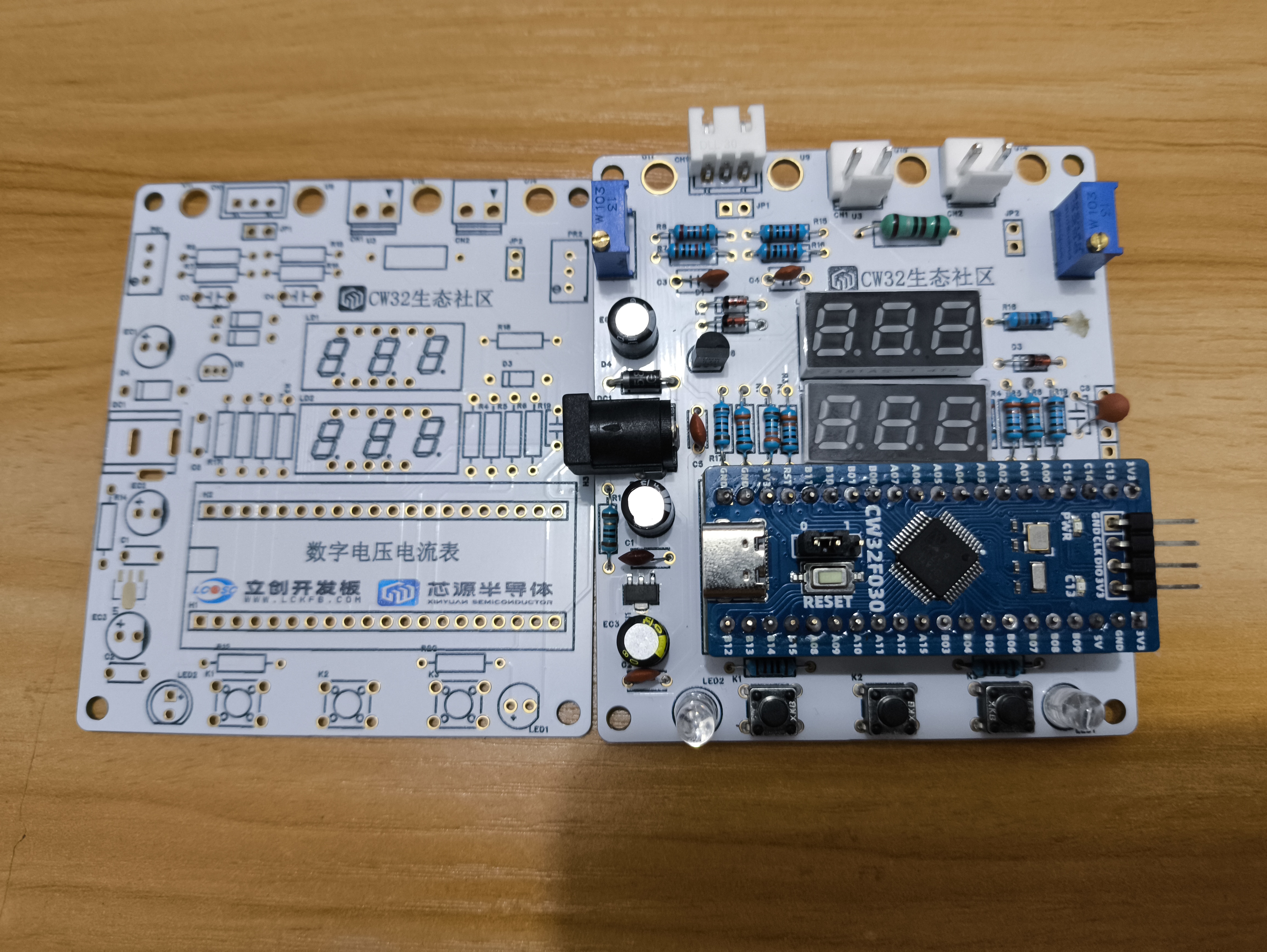
![IMG_20240821_214548.jpg]
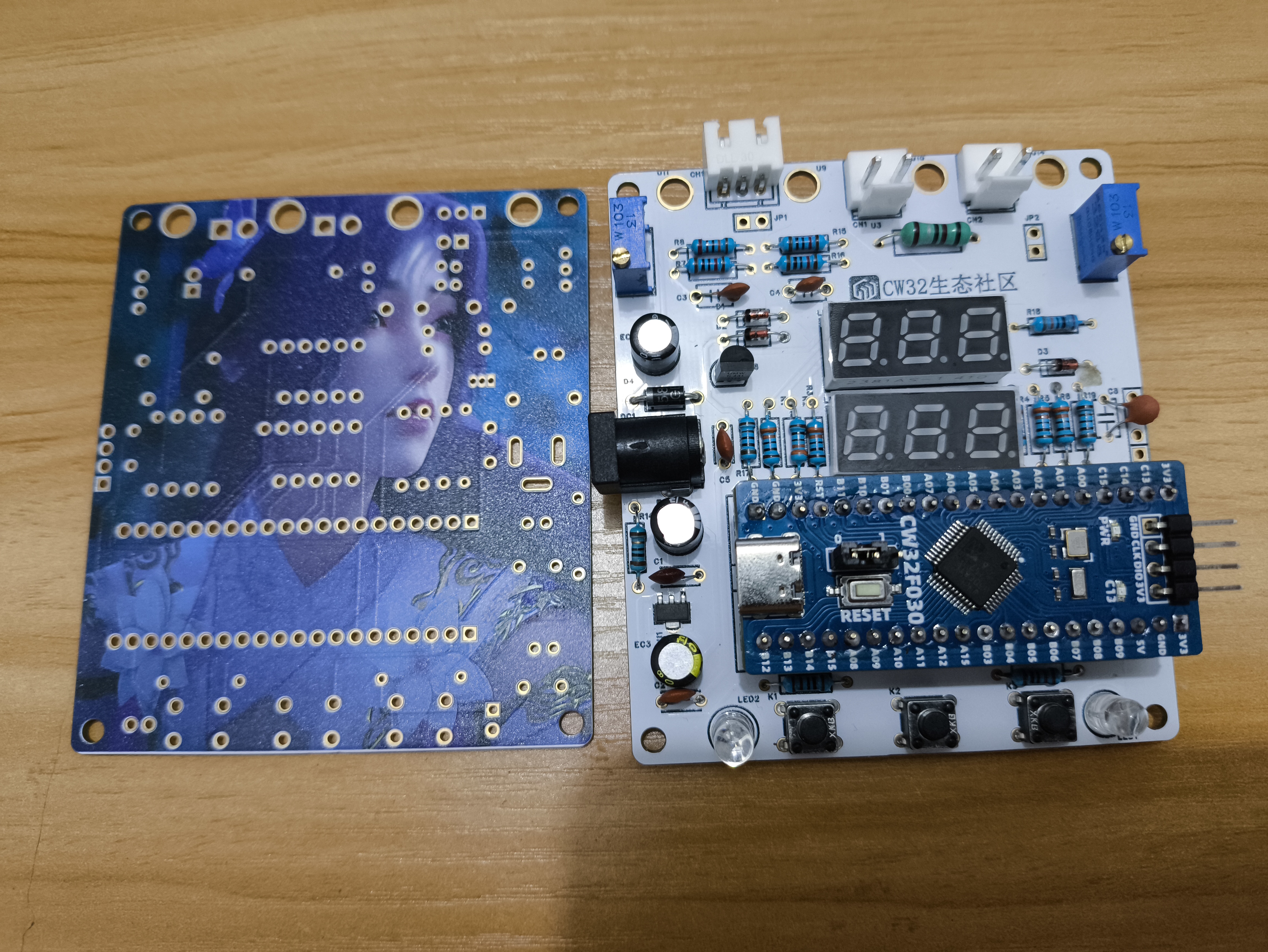
![IMG_20240821_214603.jpg]
2. Circuit Analysis
Power Supply Circuit
![voltammeter_20240716_170716.png]

LDO (Low Dropout Linear Regulator) Selection
This project uses an LDO as the power supply. Considering that most actual voltmeter products are used in industrial scenarios with 24V or 36V power supplies, this project selected the SE8550K2, which has a maximum input voltage of up to 40V, as the power supply. The main reason for not using a DC-DC step-down circuit to deal with the large voltage drop is to avoid introducing DC-DC ripple interference during the design process; a secondary reason is to reduce project costs.
This project uses series diodes for reverse connection protection because the power supply voltage of this equipment is usually higher than 5V. The 0.7V voltage drop of the diode will not affect the power supply. When the power supply voltage is low, the overall power consumption of the project is low, and the measured power supply current is low (20mA). Due to the unique structure of the Schottky diode D4 (1N5819), its VF is lower than that of general switching diodes, as shown in the figure below, with a voltage drop of approximately 0.2V or less.
In conventional circuit design, a reverse parallel diode + series fuse scheme can also achieve the purpose of reverse connection protection and circuit protection.
3. Voltage Sampling Circuit
This project uses a voltage divider circuit to achieve high voltage acquisition. The design can acquire a voltage of 100V, and the current configuration is to acquire a voltage of 0-30V.
![voltammeter_20240716_175352.png]

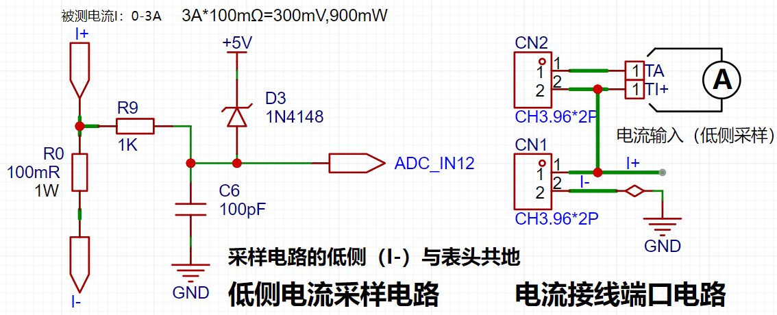
4. Current Sampling Circuit
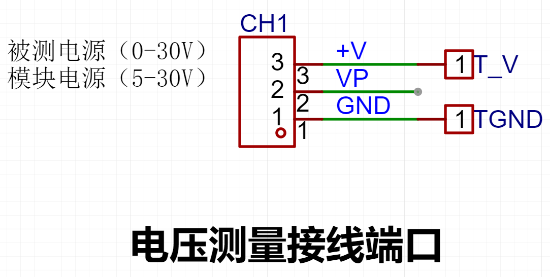
This project uses a low-side current sampling circuit for current detection. When the low side of the sampling circuit shares a common ground with the development board meter interface
, please do not solder R0! The devices labeled T_V and T_GND next to the images [
![voltammeter_20240716_181030.png]
, [![voltammeter_20240716_180705.png], and
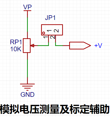
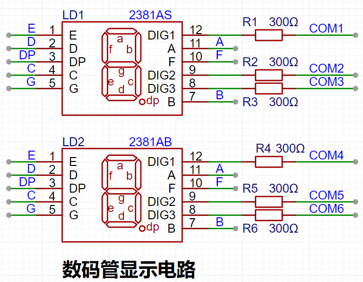
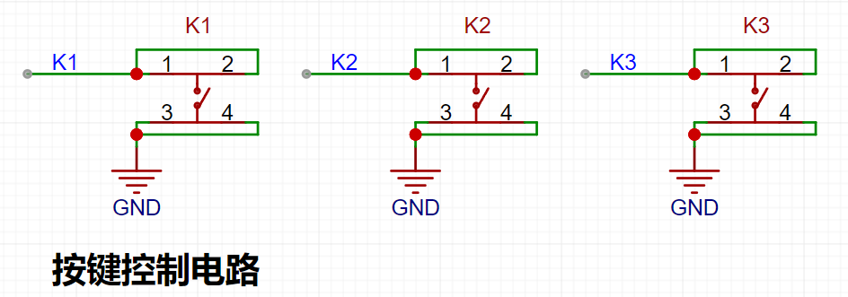
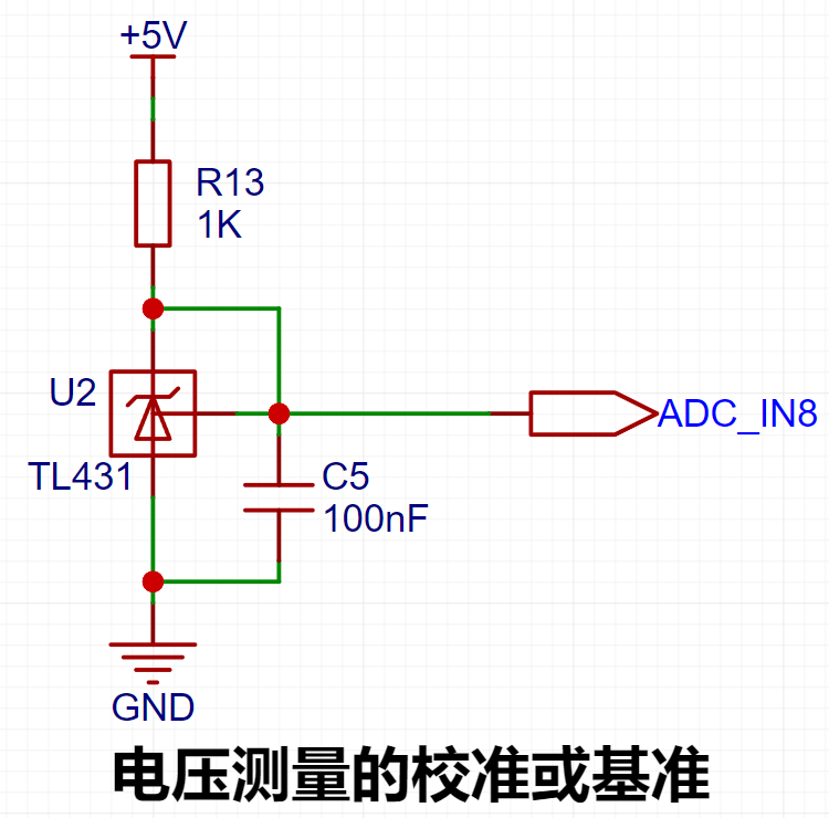
[![voltammeter_20240716_180710.png] are 2mm banana plug connectors on the development board, used to connect multimeter probes. Multimeter or high-precision benchtop digital multimeter probes can be inserted to verify the accuracy of the development board's measurements. Alternatively, 2mm banana plug multimeter probes can be inserted to replace the CH1 port for handheld measurements. The VP pin is the power supply pin for the development board and should not be connected when using the DC port. When not using DC port power and the measured value is greater than 5V and less than 30V, the power supply under test can be connected, or the board can be powered independently. When learning the measurement principles of the corresponding circuits, considering that users may not be able to easily build peripheral circuits for testing and debugging, and adhering to the principle of ease of development of the development board, auxiliary circuits for simulating voltage measurement, measurement calibration, and measurement calibration are specially set up. No external voltage is required for CH1. A multi-turn adjustable potentiometer (RP1) is used to divide the power supply voltage of the development board, which is then connected to the +V network through the internal circuitry of the development board. Note that JP1 needs to be shorted at this time; a jumper cap is sufficient, and a long-handled jumper cap is recommended. Do not short JP1 if this function is not used. 5. Digital Tube Driver This project uses digital tubes as the display unit. ![voltammeter_20240716_182642.png] This project uses two 0.28-inch three-digit common cathode digital tubes as display devices. Compared to a display screen, digital tubes have better recognition in complex environments. Depending on the actual usage environment, smaller current-limiting resistors can be used to achieve higher brightness. Furthermore, digital tubes have better mechanical properties and are not as easily damaged by external forces as display screens. In industrial and other applications requiring stability and reliability, this technology is widely used. From a development learning perspective, it facilitates more targeted learning of electronic measurement principles and related development. In this project, after actual testing, the current-limiting resistors (R1~R6) of the digital tube were configured to 300Ω. The corresponding brightness, whether for red or blue digital tubes, showed good recognizability and was soft and not glaring. Strictly speaking, the current-limiting resistors should be added to the segments; adding them to the digits would affect the display effect. In our actual design, we added them to the digits to save a few resistors, but the impact on the display was not significant. Therefore, we added them to the digits for convenience. 6. Indicator Lights This project additionally designed a power indicator light and an IO working indicator light. ![voltammeter_20240716_183456.png] Since chip I/O often has a greater current sinking capability than a current pulling capability, LED1 is designed to be I/O low-level active (on). To reduce the current consumption of the LED, some LED brightness was sacrificed, the number of device parameter types was reduced, and the current-limiting resistor for the LED was selected as 10K. Taking the F5 white LED plug-in used in this project as an example, the table below shows its electrical parameters. As can be seen from the table, the current-limiting resistor must be set to ensure the current is within 20mA. 7. Button Circuit Design ![voltammeter_20240716_183741.png] There are multiple design methods for the button control circuit. Thanks to the CW32's internal I/O ports which can be configured with pull-up and pull-down resistors, the button control circuit on the chip's periphery does not require configuration. One end of the button is connected to the MCU's I/O, and the other end is grounded. When the button is pressed, the I/O is pulled low. 8. TL431 Circuit Design for Voltage Measurement and Calibration This project adds an extra TL431 circuit to provide a 2.5V reference voltage, which can be used to provide an external voltage reference for calibrating the AD converter. From a product design perspective, due to the CW32's inherent ADC performance advantages, this circuit is not necessary. This circuit is designed on the development board for learning related application principles. ![voltammeter_20240716_183817.png] III. Software Section 1. Voltage Measurement Function Measurement Range: Supports accurate measurement of 0-30V DC voltage. Measurement Accuracy: Thanks to the high-performance ADC of the LCSC Diwenxing development board, the measurement error is less than 0.1%, meeting the needs of debugging precision electronic equipment. Overvoltage Protection: Integrated overvoltage protection circuit to prevent damage to the equipment when the maximum measurement range is exceeded. 2. Current Measurement Function Measurement Range: Supports measurement of 0-3A DC current, suitable for current detection in small electronic devices and circuits. High-Precision Measurement: Uses a high-resolution ADC for acquisition to ensure the accuracy of current measurement, with an error of less than 1%.

Overcurrent Protection: Built-in overcurrent protection mechanism to prevent equipment damage due to excessive current.
3. Real-time Data Display
Digital Tube: Measurement results are displayed in real time on the digital tube integrated on the development board. The display content is clear and intuitive, making it easy for users to monitor voltage and current changes at any time.
Interface Switching: The display mode can be switched via buttons, selecting to display only voltage and current, or display both data simultaneously.
Simultaneous Voltage
and Current Acquisition and Display:
The sampling current designed for this project is 3A, and the selected sampling resistor is 100mΩ. As shown in the figure above, the R0 sampling resistor can be soldered to 100mΩ. The passive signal is connected to the I+ terminal.
![voltammeter_20240806_163853.png]
The current calculation method is (A in unit): ADC_IN12 channel voltage / 0.1 ohm.
1.5V can also be used as the reference voltage to improve measurement accuracy.
In this experiment, the JP2 jumper can be disconnected, and R0 can be soldered to 100mΩ.
Voltage and current are acquired and converted through two ADC channels respectively. The digital tube displays six digits, with the top three digits showing the voltage value and the bottom three digits showing the current value.
A continuous sequence acquisition mode can be used in the program.
IV. Demonstration Video


 京公网安备 11010802033920号

 IDT70V9269S15PRFI


