I. Design Purpose and Background
1. To learn the concept, use and principle of ADC.
2. To learn the use and development of LCSC CW32F030C8T6.
3. After completion, it can be used as a daily tool.
II. Hardware Selection
1. The maximum input voltage of this project is as high as 30V, so the LDO is selected as SE8550K2 with a withstand voltage of 40V.
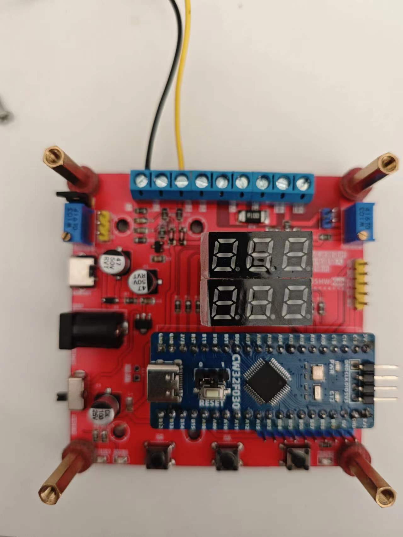
2. This project uses LCSC CW32F030C8T6 development board (core board) as the main controller.
The reasons are: (1) Wide operating voltage: 1.65V~5.5V.
(2) 12-bit high-speed ADC can reach ±1.0LSB INL 11.3ENOB multiple Vref reference voltages.
(3) It can directly drive digital tube display.
3. All resistors and capacitors in this project (except for current sampling) are 0805 packaged, and 1/8W power is sufficient. The current sampling resistor is 2512 packaged, with 3W power.
III. Main Circuits
1. Voltage Sampling Circuit
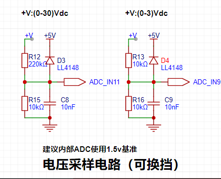
The maximum range of this project is designed to be 30V, and the ADC reference voltage is 1.5V. To reduce the power consumption of the sampling circuit, the low-voltage side resistor (R15) is selected as 10K.
Given the parameters, 1.5V/30V=0.05, and the high-side resistor is 10K/0.05=200K. A resistor slightly higher than the calculated value is selected as 220K.
The voltage divider resistor in this project is designed as 220K+10K, so the voltage division ratio is 22:1 (ADC_IN11).
An additional voltage sampling circuit is added to achieve range switching, and the voltage division ratio is 1:1 (ADC_IN9) below 3V.
This project uses diode clamping to ensure the safety of the MCU.
2. Current Sampling Circuit

The maximum current to be measured is 3A. It is not recommended that the voltage difference caused by the current sensing resistor exceed 0.5V.
Therefore, a 2512 package resistor is selected, and the corresponding current sensing resistor has a power rating of 3W and a current rise of 100mΩ.
According to the formula, 3A * 100mΩ = 300mV, 900mW can be calculated.
IV. PCB Design Knowledge Learned
1. Kelvin Connection of Current Sampling Resistor.

The Kelvin connection eliminates the influence of line resistance and contact resistance on the measurement results.
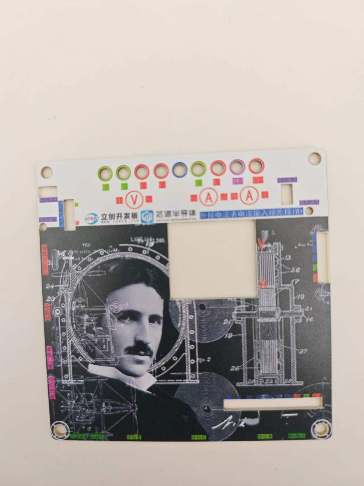
2. Silkscreen and Process.
Silkscreen printing on general PCBs is sprayed on, so when the font size is small and the line width is thick, it may become blurry, resulting in unclear markings.
It is recommended to choose the appropriate silkscreen font size and line width. Different silkscreen fonts also have different effects. Choosing a suitable font will result in better printing performance at the same line width and font size.
Inappropriate selection will cause the silkscreen to be illegible.
V. Software Code
. Since I had just learned about ADCs, I directly used Experiment Nine: Digital Voltage and Current Meter with Calibration Function.
Five working modes were defined. The K1 key is used to switch the display mode. The K2 key sets the parameter value for the corresponding mode and saves it to FLASH. The K3 key returns to mode 0.
Mode 0: Displays normal voltage and current values (the upper row of digital tubes displays the voltage value *.V or .*V automatically, the lower row displays the current value _.**A).
Mode 1: 5V voltage calibration setting. The upper row of digital tubes displays 5.05. The lower row displays the current voltage value _.V or ._V. In this mode, the multimeter should be set to 5.00V when measuring the measured bit. Pressing the K2 key will calibrate the current value to 5V.
Mode 2: 15V voltage calibration setting. The upper row of digital tubes displays 5.15. The lower row displays the current voltage value _.V or ._V. In this mode, the multimeter should be set to 15.0V when measuring the measured bit. Pressing the K2 key will calibrate the current value to 15V.
Mode 3: 0.5A current calibration setting. The upper row of digital tubes displays A.0.5. The lower row displays the current current value _.**A. Pressing the K2 key calibrates the current value to 0.5A.
Mode 4: Current 1.5A calibration setting. The upper row of digital tubes displays A.1.5. The lower row displays the current value *.**A. Pressing the K2 key calibrates the current value to 1.5A.
VI. Assembly Instructions:
The PCB component board and decorative cover are connected using M3 screws and M3-22MM hexagonal studs.
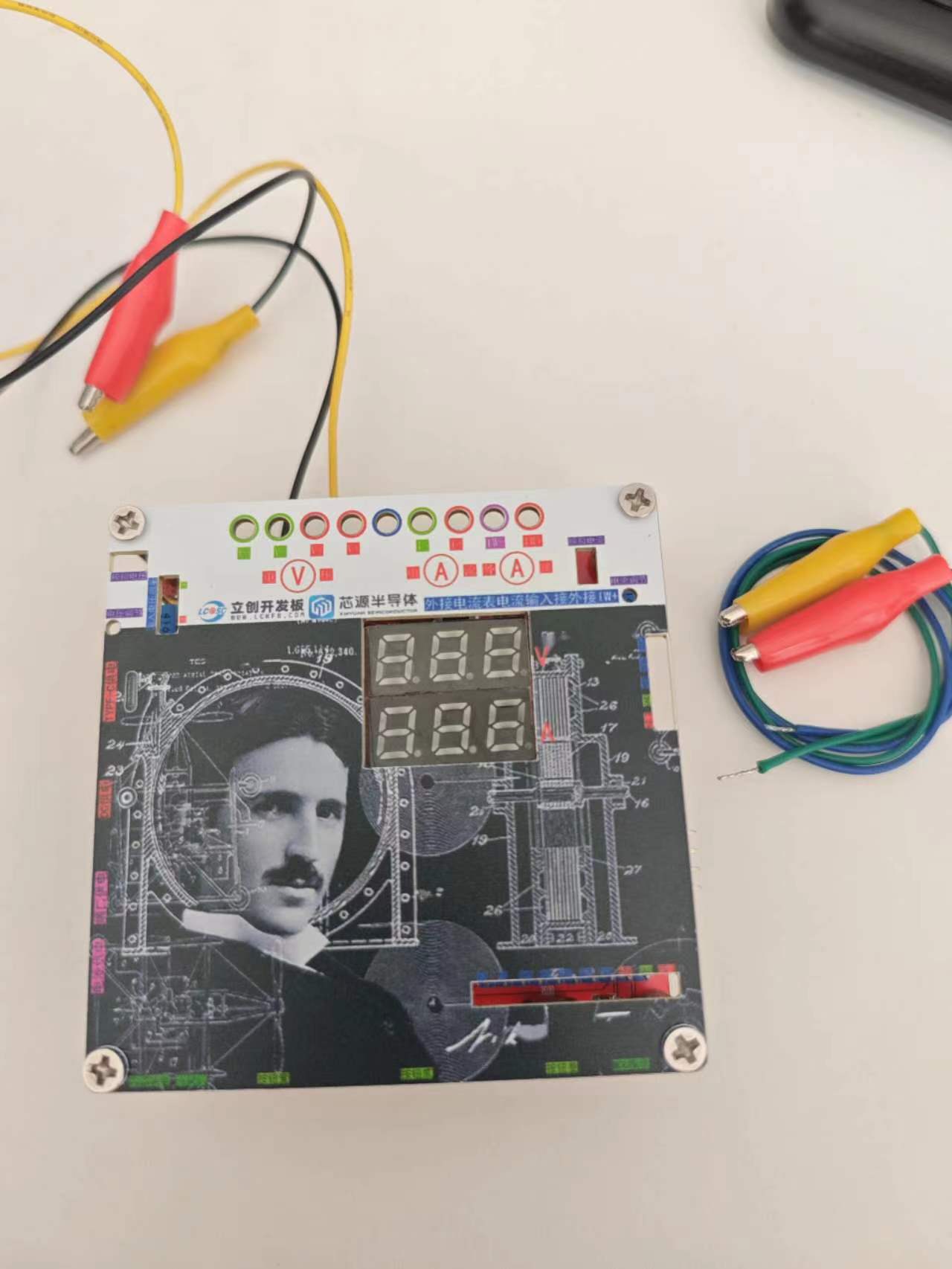
VII. Function Introduction:
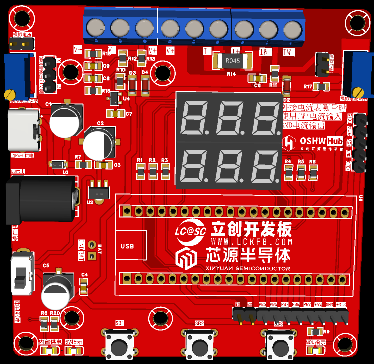
This project can be powered by DC input and TYPE-C input, and an external power supply is also available with a reserved BAT interface.
When the input voltage measurement jumper is in the ON position, the supply voltage can be measured.
When the input voltage measurement jumper is in the OFF position and the analog voltage jumper is shorted, the variable analog voltage can be measured by adjusting the analog voltage potentiometer.
Shorting the analog current also allows for the measurement of variable current output using the analog current potentiometer.


 京公网安备 11010802033920号

 102-624-02S-P31-B12


