I. Design Background
Learning to design and build a digital voltmeter and ammeter is highly beneficial for improving one's professional skills. The digital voltmeter and ammeter project covers multiple aspects, including microcontroller circuit design and implementation, signal acquisition and processing circuit design, user interface development and optimization, and product appearance design. It integrates knowledge from multiple fields such as electronics, microcontroller programming, circuit design, and industrial design. Considering the learning pace and knowledge absorption capacity of beginners, we have specially launched this introductory-level digital voltmeter and ammeter project, which is very suitable for beginners in electronics and those who want to learn more about microcontroller applications.
II. Hardware Design
1. Power Supply Circuit
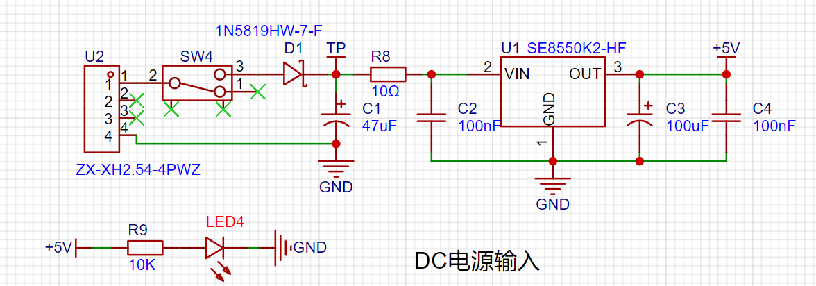
LDO (Low Dropout Linear Regulator) Selection This project uses an LDO as the power supply. Considering that most actual voltmeter products are used in industrial scenarios with 24V or 36V power supplies, this project selected the SE8550K2, which has a maximum input voltage of up to 40V, as the power supply. The main reason for not using a DC-DC buck converter to handle the large voltage drop is to avoid introducing DC-DC ripple interference during the design process; a secondary reason is to reduce project costs.
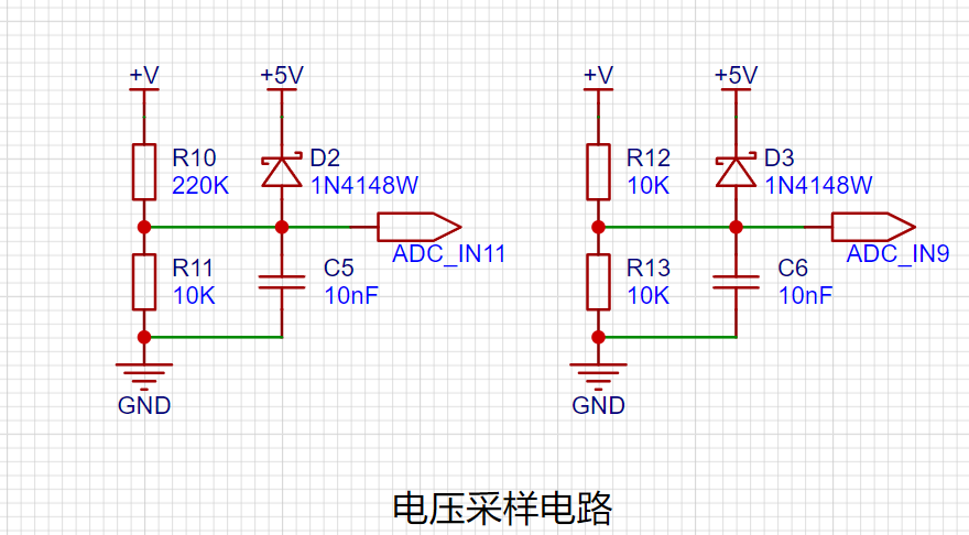
2. Voltage Sampling Circuit:
The voltage divider resistors in this project are 220K+10K, therefore the voltage division ratio is 22:1 (ADC_IN11).
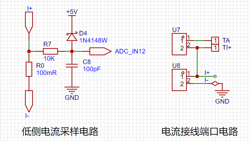
3. Current Sampling Circuit:
This project uses a low-side current sampling circuit for current detection. The low-side of the sampling circuit shares a common ground with the meter interface on the development board.
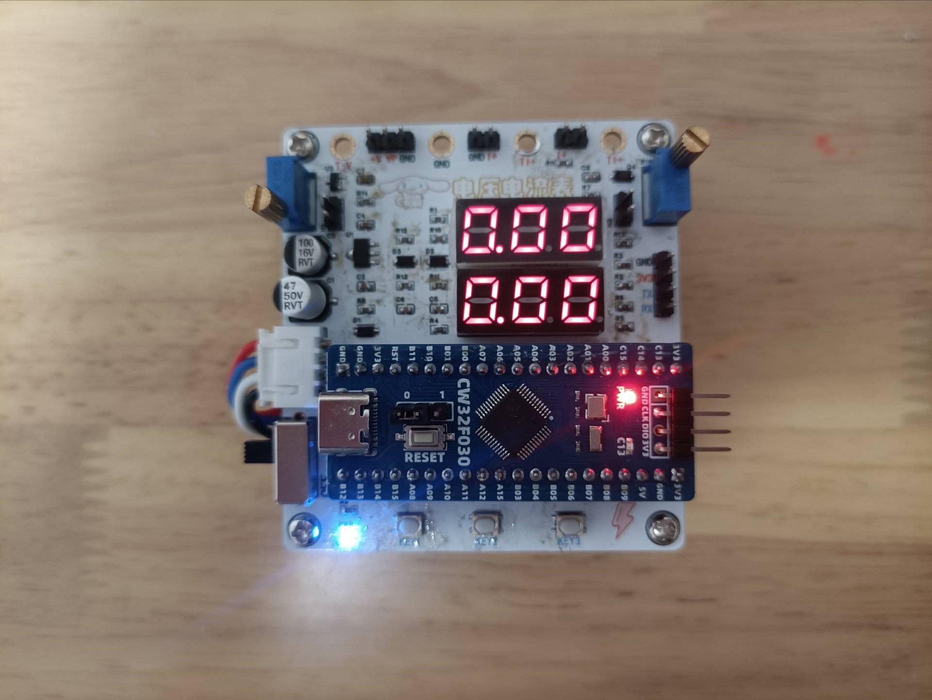
4. Digital Tube Display:
This project uses a digital tube as the display unit.

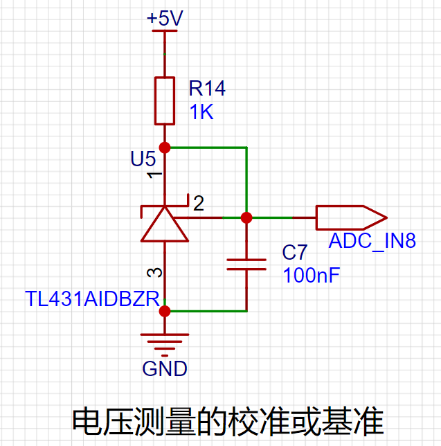
5. TL431 Circuit Design for Voltage Measurement Calibration:
This project adds an extra TL431 circuit to provide a 2.5V reference voltage, which can be used to provide an external voltage reference for calibrating the AD converter. From a product design perspective, due to the inherent ADC performance advantages of the CW32, this circuit is not necessary. This circuit is designed on the development board for learning related application principles.
7. Button Circuit Design

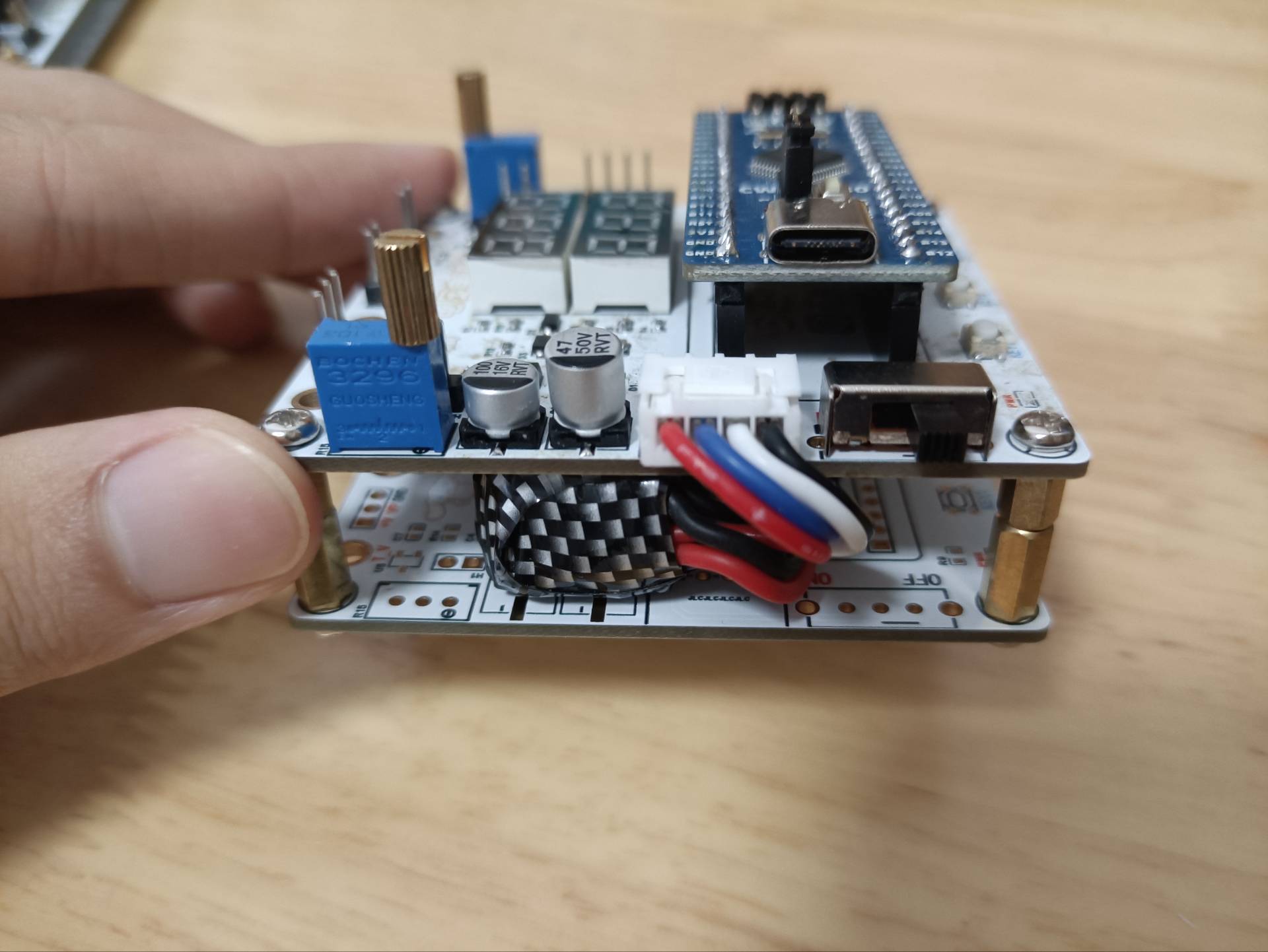
III. Physical Object and Demonstration
1. Physical Object Diagram
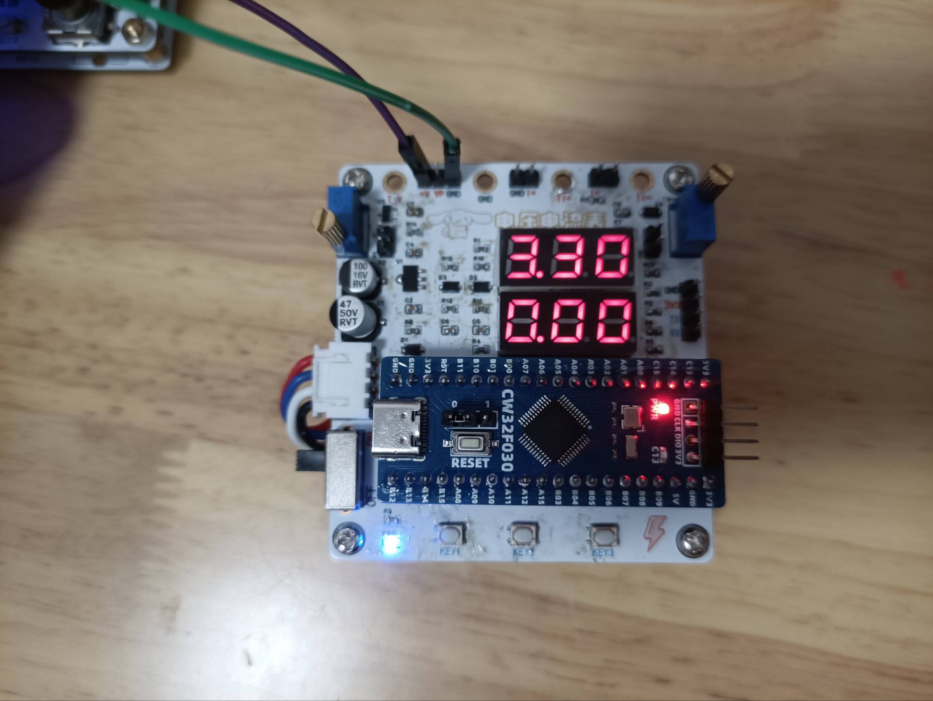
2. Voltage and Current Measurement Demonstration
Voltage Measurement
Current Measurement

PDF_Voltage and Current Meters.zip
Altium_voltmeter_currentmeter.zip
PADS_Voltage and Current Meter.zip
BOM_Voltage and Current Meter.xlsx
92991
Voltmeter and Ammeter
This design is a simplified voltmeter and ammeter. In actual welding, voltage and current terminals are not welded; instead, a potentiometer is used to simulate voltage and current testing. This design can measure voltages from 0-30V, with a sampling current of 3A and a sampling resistor of 100mΩ.
This CW32030-based voltmeter and ammeter

design is a simplified version. In actual soldering, voltage and current terminals are not soldered; instead, potentiometers are used to simulate voltage and current testing. This design can measure voltages from 0-30V, with a sampling current of 3A and a sampling resistor of 100mΩ.
The hardware design uses a DC
input power supply circuit

, stabilizing the voltage to 5V using an 8550. A small resistor R14 is connected in series to serve two purposes: firstly, to divide the voltage, preventing excessive overheating of the LDO if the DC input voltage is too high; secondly, to reduce the excessive voltage difference between VIN and VOUT of the 8550; and thirdly, to act as a fuse, burning out in case of a short circuit to protect the circuit. LD_PWR is the power indicator light, illuminating when a stable 5V is generated on the development board.
The MCU
uses the LCSC CW030 core board as the main controller. The CW030 has a wide operating voltage range: 1.65 - 5.5V. Furthermore, it features a 12-bit high-speed ADC, and the reference voltage Vref can be selected from 1.5V, 2.5V, and VDD, offering more options compared to the STM32F103 which only supports VDD. Lower reference voltages can result in lower resolution.
The digital tube

display circuit uses a 0.28-inch three-digit common-cathode digital tube. In this design, LD1 displays voltage information, and LD2 displays the acquired current information. The digital tube display uses dynamic scanning, utilizing the persistence of vision effect. In reality, only one digit can be lit at a time; as long as the refresh rate is fast enough, it appears as if all digits are displayed simultaneously. The MCU's GPIO
for the button circuit

is configured as a pull-up input. When the button is not pressed, the GPIO exhibits a weak pull-up; when the button is pressed, the button circuit is pulled down to ground.
Voltage sampling

uses two resistors to divide the +V voltage by a ratio of 22:1. The voltage is acquired by the microcontroller, and the +V voltage is calculated backwards.
+V = ADC / (R7 / (R7+R8)).

A potentiometer is used to simulate voltage. A jumper cap is used to short-circuit the two pins of JP1, allowing the voltage signal from the potentiometer to be sent to +V. The voltage value is then measured again via voltage sampling.
Current sampling:

This design uses a sampling current of 3A. The selected sampling resistor R0 is 100mΩ (1W package).
R9 is connected in series in this design to provide some current, preventing high current from damaging the MCU's ADC pins. Combined with C6, it forms an RC low-pass filter, reducing the impact of high-frequency noise on ADC sampling.

Current testing is simulated using a potentiometer. A jumper cap is used to short-circuit JP2. R17 and the voltage divider at the upper and lower ends of the potentiometer are used (R0 is not soldered when using a potentiometer to simulate voltage measurement). The voltage at the lower end of the potentiometer is measured.
Software design
code is detailed in the attached demonstration video
.
MyProject.7z
Project.hex
Demo.mp4
PDF_Voltage and Current Meters.zip
Altium_voltmeter_currentmeter.zip
PADS_Voltage and Current Meter.zip
BOM_Voltage and Current Meter.xlsx
92992
Voltmeter and Ammeter
CW32-based digital voltmeter and current meter with calibration function
This project uses the LCSC CW32F030C8T6 development board. Detailed tutorials and materials are available on the LCSC development board website, including the "CW32 Digital Voltmeter and Ammeter Training Camp Project Tutorial Document." This project is
a complete replica of the training camp project, with no changes to the circuitry or code.
Digital Voltmeter and Ammeter with Calibration Function
1. Concept of
Calibration Calibration is the process of compensating for instrument system errors by measuring the deviation of a standard, thereby improving the accuracy and precision of the instrument or system. To improve the measurement accuracy and precision of the voltmeter and ammeter, calibration is required.
The common calibration principle is as follows:
Assume a sampling system where the AD section can obtain digital quantities, corresponding to physical quantities such as voltage (or current).
If an AD value point Xmin is calibrated at the "zero point" and an AD value point Xmax is calibrated at the "maximum point", according to the principle that "two points form a straight line", a straight line connecting the zero point and the maximum point can be obtained. The slope k of this line is easy to find. Then, by applying the equation of the straight line to solve for each point X (AD sample value), the physical quantity (voltage value) corresponding to the AD value can be obtained:

The slope k in the figure above is:
k = (Ymax - Ymin) / (Xmax - Xmin)
(because the first point is the "zero point", Ymin = 0 above).
Therefore, the physical quantity corresponding to the AD value at any point in the figure above is:
y = k × (Xad - Xmin) + 0.
The above algorithm only performs calibration between the "zero point" and the "maximum point". If the intermediate AD sample value is used, it will bring a large error in the corresponding physical quantity. The solution is to insert more calibration points.
As shown in the figure below, four calibration points (x1, y1), (x2, y2), (x3, y3), and (x4, y4) are inserted respectively.
This results in a line that is no longer a straight line, but a "reflected line" (equivalent to segmented processing). To find the voltage value corresponding to a point Xad between x1 and x2:
y = k × (Xad – X1) + y1.
It can be seen that the more calibration points inserted, the higher the accuracy of the physical value.
In voltage and current meter measurements, a "voltage and current calibration board" or "multimeter" can be used to calibrate the collected voltage and current. The more calibration points, the more accurate the measurement.
2. The project code file is as follows:
Link: https://pan.baidu.com/s/12OWqnW4XG8EGxlk9wCQoqw?pwd=LCKF Extraction code: LCKF.
The reference example uses 3 calibration points. The voltage calibration points are 0V, 5V, and 15V. The current calibration points are 0A, 0.5A, and 1.5A.
3. Calibration Operation Method for this Experiment
This example uses button operation for calibration. The specific operation method is as follows:
Define 5 working modes. The K1 key is used to switch the display mode. The K2 key sets the parameter value for the corresponding mode and saves it to FLASH. The K3 key returns to mode 0.
Mode 0: Displays normal voltage and current values (the upper row of the digital tube displays the voltage value *.V or .*V automatically, the lower row displays the current value _.**A).
Mode 1: 5V voltage calibration value setting. The upper row of the digital tube displays 5.05. The lower row displays the current voltage value _.V or ._V. In this mode, the multimeter should be set to 5.00V to measure the measured bit. After pressing the K2 key, the current value is calibrated as a 5V voltage value.
Mode 2: 15V voltage calibration value setting. The upper row of the digital tube displays 5.15. The lower row displays the current voltage value _.V or ._V. In this mode, the multimeter should be set to 15.0V to measure the voltage of the measured part. After pressing the K2 key, the current value is calibrated to 15V.
Mode 3: Current 0.5A calibration setting. The upper row of the digital display shows A.0.5. The lower row displays the current current value _.**A. After pressing the K2 key, the current value is calibrated to 0.5A.
Mode 4: Current 1.5A calibration setting. The upper row of the digital display shows A.1.5. The lower row displays the current current value *.**A. After pressing the K2 key, the current value is calibrated to 1.5A.
Experiment 9: Digital Voltmeter and Ammeter with Calibration Function.rar
PDF_Voltage and Current Meters.zip
Altium_voltmeter_currentmeter.zip
PADS_Voltage and Current Meter.zip
BOM_Voltage and Current Meter.xlsx
92993
electronic


 京公网安备 11010802033920号

 S553-5999-92


