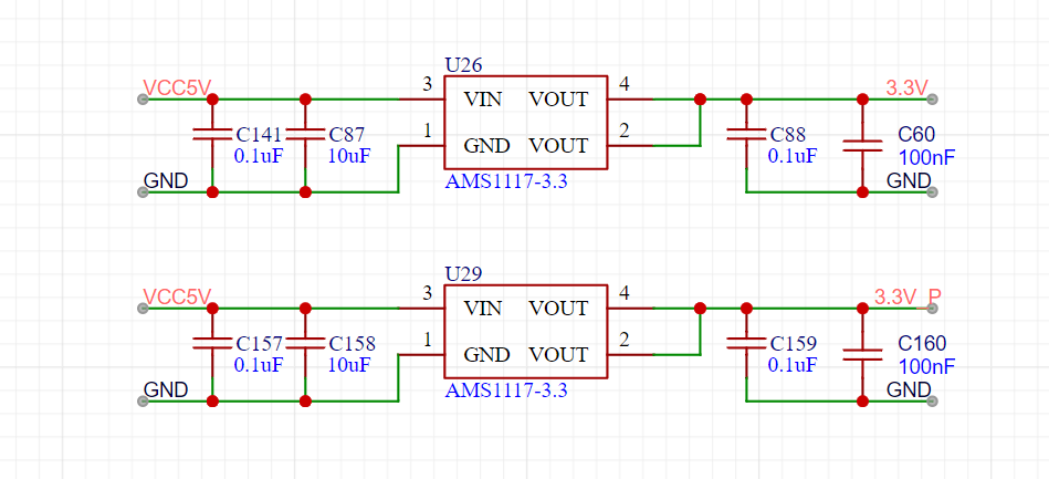
 . Regarding external power to the core board, a 5V input is recommended. The board uses two diodes for 5V to prevent reverse current, so a higher voltage can be supplied to the 5V header for external power, but since it's an LDO, a large voltage difference is not advised.
  For the microcontroller's USB, R155, R54, and R153 can be removed. They were included here because it's a direct copy of the STM32F1 board, but they're not actually used.
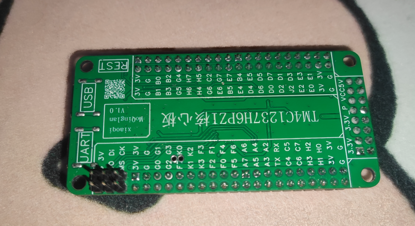
  The only user-defined I/O on the board is the LED on PB4, which can be used to indicate the board is still functional.
  A debugging interface is provided here; my J-Link is perfectly adequate for testing.
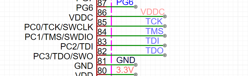

 Note that
All reference designs on this site are sourced from major semiconductor manufacturers or collected online for learning and research. The copyright belongs to the semiconductor manufacturer or the original author. If you believe that the reference design of this site infringes upon your relevant rights and interests, please send us a rights notice. As a neutral platform service provider, we will take measures to delete the relevant content in accordance with relevant laws after receiving the relevant notice from the rights holder. Please send relevant notifications to email: bbs_service@eeworld.com.cn.
It is your responsibility to test the circuit yourself and determine its suitability for you. EEWorld will not be liable for direct, indirect, special, incidental, consequential or punitive damages arising from any cause or anything connected to any reference design used.
Supported by EEWorld Datasheet
EEWorld
subscription
account

EEWorld
service
account

Automotive
development
community

Robot
development
community

About Us Customer Service Contact Information Datasheet Sitemap LatestNews


Room 1530, 15th Floor, Building B,
No.18 Zhongguancun Street,
Haidian District,
Beijing, Postal Code: 100190
China
Telephone: 008610 8235 0740
 京公网安备 11010802033920号

 2200CAH400123MB


