 This project uses an LDO as the power supply. Considering that most voltmeter products are used in industrial scenarios with 24V or 36V power supplies, this project selected the SE8550K2, which has a maximum input voltage of 40V. However, during the experimental debugging process, a Type-C interface was used to directly power the CW32, which provides power via a Type-C port.
  The voltage measurement section has two ranges: one uses a 220kΩ:10kΩ voltage divider, with an input voltage to ADC measurement voltage ratio of 23:1; the other is 2:1. The experimental code in this project uses the first method, which has a wider measurable voltage range. If the ADC reference voltage is set to 1.5V, the maximum measurable voltage is 1.5*23=34.5V. Method 2 has a maximum voltage of 3V, but with significantly improved accuracy. Diode clamping ensures MCU safety. Considering potential fluctuations in the tested power supply, a 10nF filter capacitor is connected in parallel with the low-side voltage divider resistor in the circuit design to improve measurement stability.
  Analog voltage measurement is also provided; in the absence of an external power supply, this device can be used to verify the accuracy of the ADC's voltage measurement function.
  The T_V and T_GND components are the 2mm banana plug connectors on the development board, used to connect multimeter probes. Multimeter or high-precision benchtop digital multimeter probes can be inserted to verify the accuracy of the development board's measurements. Alternatively, a 2mm banana plug multimeter probe can be inserted to replace the CH1 port for handheld measurement; however, in my experiment, I directly shorted the multimeter probes to +V and GND for measurement.
 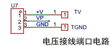 Current Sampling Section: The sampling current designed for this project is 3A, and the selected sampling resistor (R0) is 100mΩ. Since this project does not use an amplifier circuit, a larger sampling resistor is needed to obtain a higher measured voltage for measurement. Considering that a larger resistor would result in a larger voltage drop and higher power consumption, an unlimitedly larger resistor cannot be chosen. This project uses a 1W package resistor, corresponding to a power rise of 1W. Based on the above data, a 100mΩ current sensing resistor was selected for this project. According to the formula, 3A * 100mΩ = 300mV, 900mW.
  In actual use, the voltage at I+ is simulated as the voltage drop across the unsoldered 100mΩ sampling resistor. At this time, the simulated measured current value Imeasured = the voltage value Vi + ÷ 100mΩ, which is also exactly equal to the measured voltage value multiplied by 10. That is, it provides a simulated current measurement of 0~2.38A.
 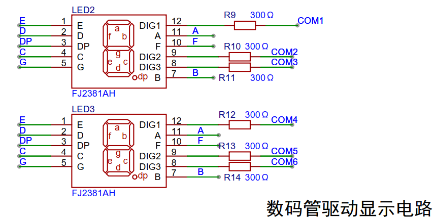 The CW32's I/O port can be configured with internal pull-up and pull-down resistors, but the external button control circuit does not require configuration. One end of the button is connected to the MCU's I/O, and the other end is grounded. When the button is pressed, the I/O is pulled low.
 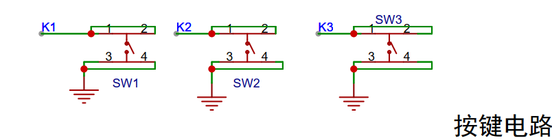 This project adds an additional TL431 circuit to provide a 2.5V reference voltage, which can be used to provide an external voltage reference for calibrating the AD converter.
 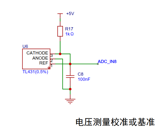 The PCB section lacks copper plating on the current acquisition section. It's important to note that a large current flows through I-, which is considered "power ground." Even though this point is grounded, current fluctuations can cause network level changes, making it a potential source of interference. The GND network is the negative terminal of the meter's power supply, i.e., "signal ground." Since the microcontroller's AGND and the meter's GND are not isolated, the meter's GND can be considered a "sensitive ground," requiring protection from interference.
  Testing revealed that pin PA8, connected to the COM1 of the digital tube, cannot receive a low level in push-pull output mode, preventing the digital tube from lighting up properly. Therefore, the code is only designed to display voltage and current values for five digits.
All reference designs on this site are sourced from major semiconductor manufacturers or collected online for learning and research. The copyright belongs to the semiconductor manufacturer or the original author. If you believe that the reference design of this site infringes upon your relevant rights and interests, please send us a rights notice. As a neutral platform service provider, we will take measures to delete the relevant content in accordance with relevant laws after receiving the relevant notice from the rights holder. Please send relevant notifications to email: bbs_service@eeworld.com.cn.
It is your responsibility to test the circuit yourself and determine its suitability for you. EEWorld will not be liable for direct, indirect, special, incidental, consequential or punitive damages arising from any cause or anything connected to any reference design used.
Supported by EEWorld Datasheet
EEWorld
subscription
account

EEWorld
service
account

Automotive
development
community

Robot
development
community

About Us Customer Service Contact Information Datasheet Sitemap LatestNews


Room 1530, 15th Floor, Building B,
No.18 Zhongguancun Street,
Haidian District,
Beijing, Postal Code: 100190
China
Telephone: 008610 8235 0740
 京公网安备 11010802033920号

 M57962


