It's time to equip your optical modem, soft router, switch, and other devices with a cost-effective, high-performance platinum power supply
. One power supply solves the power needs of all your 12V devices.
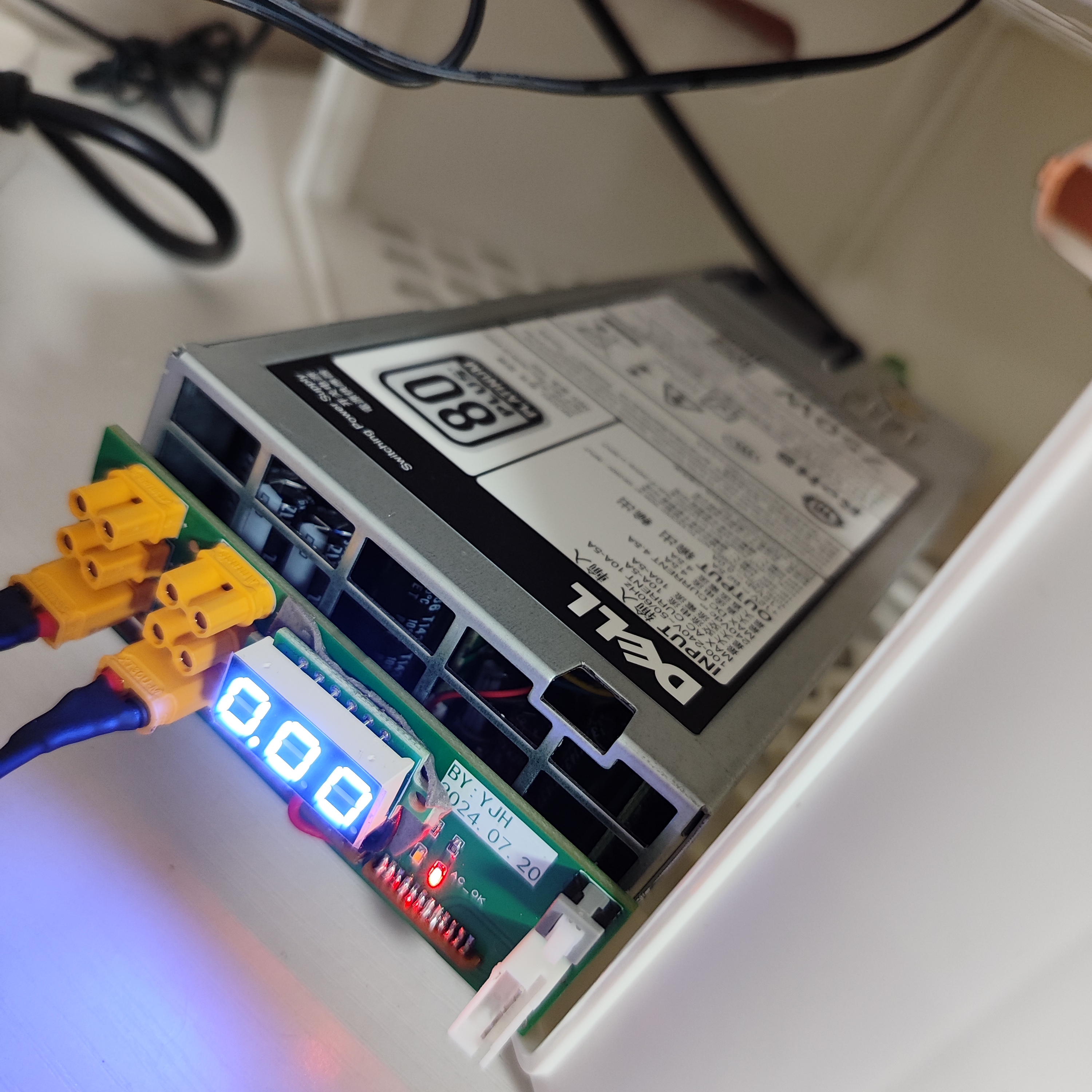
No expensive connectors are needed; this direct-soldering DELL server power supply adapter board provides unified power to soft routers, optical modems, switches, and other devices. It includes an XH2.54 PMBus interface for reading power supply voltage, current, and power information.
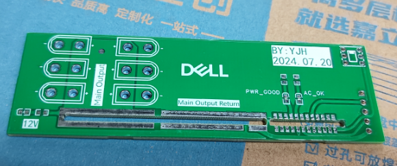
The finished product is shown in the image below. There are only six surface-mount components in total; you can leave them all unsoldered if you don't need indicator lights. Only the switch needs to be soldered (or you can connect them all together with a lump of solder, saving you the trouble of soldering the switch itself).
PDF_Dell Server 750W Power Adapter Board.zip
Altium_Dell Server 750W Power Adapter Board.zip
PADS_Dell Server 750W Power Adapter Board.zip
BOM_Dell Server 750W Power Adapter Board.xlsx
93548
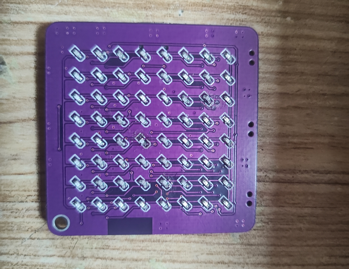
STC Bluetooth serial port LED board
STC Bluetooth serial port LED lighting, with 64 onboard LEDs and a Dobtm03 LED from Baidu Cloud Mall.
It's been verified that the Bluetooth power control was modified once; a wire was missing, but it's been fixed (on the MOSFET side). The modified one hasn't been verified yet, but it should be fine. The specific function hasn't been decided yet; it could be used for pendants, toys, etc.
My 662k is still at school for the holidays; I'm using an 1117 jumper cable instead. That should work fine.
VID_20240724_185224.mp4
VID_20240721_000220.mp4
doBT-01 series Bluetooth documentation.zip
lanyachuankou_v7.4.7_downcc.com.apk
stc8h8k64_serial port LED.zip
PDF_stc Bluetooth serial port LED board.zip
Altium_stc Bluetooth serial port LED board.zip
PADS_stc Bluetooth serial port LED board.zip
BOM_stc Bluetooth serial port LED board.xlsx
93550
TPS5430 Negative Voltage Module -12V Low Ripple
A negative voltage module using TPS5430 outputs -12V, and low ripple output is achieved using a secondary LC filter.
PDF_TPS5430 Negative Voltage Module -12V Low Ripple.zip
Altium_TPS5430 Negative Voltage Module -12V Low Ripple.zip
PADS_TPS5430 Negative Voltage Module -12V Low Ripple.zip
BOM_TPS5430 Negative Voltage Module -12V Low Ripple.xlsx
93551
A small mobile phone based on the Taishan School
This project is a learning project submitted to the LCSC Taishan Training Camp.
The knowledge points involved include: circuit design, PCB design, PCB soldering, Linux device trees and drivers, structural design, and 3D printing.
I. Project Description
This project is a small mobile phone project based on the LCSC development board "Taishanpai". The learning content includes: Linux compilation environment setup, SDK compilation, common Linux commands, device tree, screen selection and debugging, screen touch driver, etc.
The main tasks in this project include designing and soldering a 3.1-inch MIPI screen adapter board, designing and 3D printing the small mobile phone casing. The program currently uses the "default landscape" firmware. After assembly, I will try writing my own program. Based on
my design of the "3.1 MIPI adapter board" in the training camp, I added "12V PD power supply" and "UART", both of which use Type-C connectors. This increases the distance between the "Taishanpai" and the "adapter board", so the length of the "surface nut post" and "pogo pin" is insufficient and needs to be reselected. At the same time, the casing needs to be redesigned to increase the "thickness" of the phone, and two new "Type-C" interfaces need to be added to the casing.
Because the length of the pogo pin has a range (before and after spring compression), the length of the surface nut post is determined first, and then the pogo pin is selected. After testing in SW, it was found that the distance between "Taishanpai" and "adapter board" changed from 3mm to 6mm, which is enough to fit the typec socket. Therefore, a 6mm high surface mount nut post was selected on the board, and a 6.5mm high pogo pin was selected on the board (6.5 before compression, 4.5 at the compression limit).
During the learning process in the training camp, most of the time I watched the live replays and watched each video carefully. Because the original tutorials jump back and forth between multiple links, it is not easy for a beginner to get an overall idea. Therefore, based on the original tutorials, I wrote CSDN according to my own understanding, sorted out the ideas, and "added" the problems I encountered in the learning process. There are some articles with a high degree of completion, the links are as follows:
(1) Environment setup and SDK compilation
(2) Common Linux commands
(3) Linux device tree
(4) Screen selection and debugging
(5) Comprehensive project
Note: The above articles are for my own reference in the future and are more applicable to myself.
The official tutorial for Taishanpai is available here. Part
II: Schematic Design
. This schematic design refers only to the 3.1 MIPI adapter board. Most of the circuitry follows the official tutorial, so the principles will not be explained further; only the general approach will be outlined.
The wiring sequence of the Taishanpai 3.1 MIPI interface is inconsistent with that of a 3.1-inch screen, so an adapter board is needed to match the wiring sequences.
Taishanpai itself has a backlight circuit, which is led out through the 3.1 MIPI interface, with a maximum output of 110mA. However, the maximum backlight current that a 3.1-inch MIPI screen can withstand is 25mA. Directly connecting the Taishanpai's backlight circuit to the screen could cause it to overheat or even burn out. Therefore, the 3.1 MIPI adapter board is designed with two backlight paths: one provided by the Taishanpai MIPI connector, and the other by the onboard backlight circuit. These are selected using a 0Ω resistor.
The 3V3 of the Taishanpai MIPI connector provides power to the onboard backlight circuit, and the PWM signal controls the output voltage of the onboard backlight circuit. TP's I2C is converted to PWM via an I2C-to-PWM chip. Therefore, TP's I2C terminal controls both the touchscreen and the backlight.
The newly added PD power supply and UART circuit are as follows:

CH224K uses a single resistor configuration; CFG1 is grounded via a 24K resistor, which will induce a 12V voltage.

III. PCB Design:
See notes for the comprehensive project.
IV. Purchase Items List:
Material
Model
Reference Link
:
Taishanpai
2+16
https://lckfb.com/project/detail/lctspi-2g-16g?param=baseInfo
Recommended version: 2+16.
MIPI adapter board
is not
available in this project
; you can directly prototype it and then purchase components according to the BOM, soldering the adapter board. RTC connector without Pogo pins and surface mount nuts are sold separately.
Pogo pins with
a 6.5mm surface mount height are available here
: https://item.taobao.com/item.htm?u=f352jcuff2f2&id=750082995689&spm=a1z09.2.0.0.47fc2e8dDghyEo
6.5mm surface mount
nuts are available here: https://detail.tmall.com/item.htm?u=f352jcuf5bf0&id=675714153951&spm=a1z09.2.0.0.47fc2e8dDghyEo&skuId=5033314679469 31-pin MIPI FPC cable with a 0.3mm surface mount height is also available here
: https://detail.tmall.com/item.htm?u=f352jcuf5bf0&id=675714153951&spm=a1z09.2.0.0.47fc2e8dDghyEo&skuId=5033314679469 Type A, 50mm long, same direction: https://item.taobao.com/item.htm?u=f352jcuf07f9&id=618662306027&spm=a1z09.2.0.0.5d7f2e8dnF3uzf One TP-Link FPC cable, 26 pins, 0.5mm, Type A, 50mm long, same direction: https://item.taobao.com/item.htm?u=f352jcuf69d2&id=555563074622&spm=a1z09.2.0.0.5d7f2e8dnF3uzf One cable , M2x12 screws. https://detail.tmall.com/item.htm?id=616455063246&spm=a1z09.2.0.0.5d7f2e8dnF3uzf&u=f352jcuf57ce No need to buy nuts, at least 3 are required. V. Acknowledgements: Thanks to Engineer Wu, the development team, and the LCSC development board team.
6d115d85579ffd75efaae2673a18bab5.mp4
PDF_A Small Mobile Phone Based on the Taishan School.zip
Altium - A small mobile phone based on the Taishan School.zip
PADS_A small mobile phone based on the Taishan School.zip
BOM_Based on Taishanpa's Small Mobile Phone.xlsx
93552
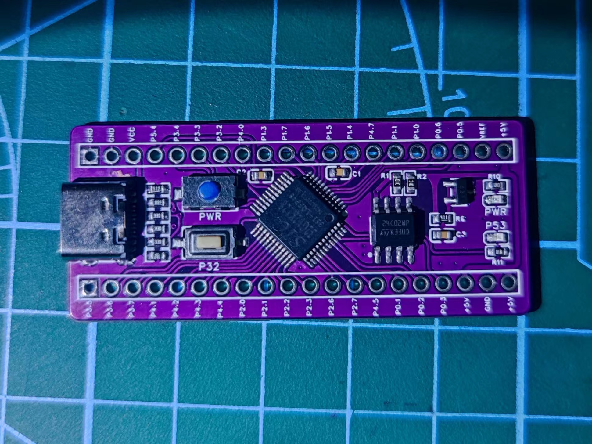
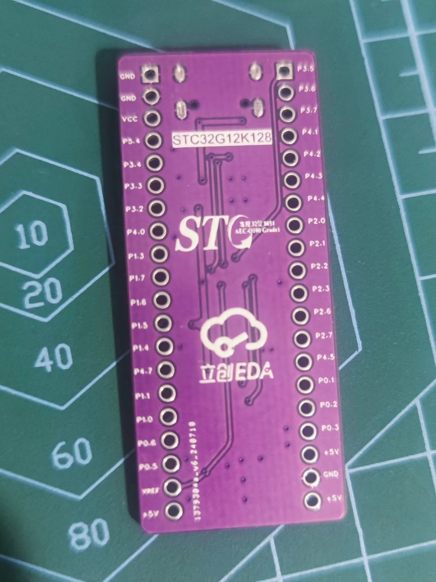
STC32G12K128 microcontroller development board
STC32G12K128
Minimum system board based on STC32G12K128, USB download, no serial port chip required.
PDF_stc32g12k128 microcontroller development board.zip
Altium_stc32g12k128 microcontroller development board.zip
PADS_stc32g12k128 microcontroller development board.zip
BOM_stc32g12k128 microcontroller development board.xlsx
93554
electronic


 京公网安备 11010802033920号

 21008ESD


