The I/O allocation for this project is only applicable to the CW32F030C8T6 minimum system board from Chipone Semiconductor. For specific allocation details, please refer to the schematic diagram,
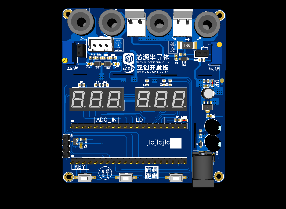
final effect diagram, and finished product diagram.
Training Camp Course Materials Download Area:
1. LCSC Development Board LOGO (See Attachment)
2. Chipone Semiconductor LOGO (See Attachment
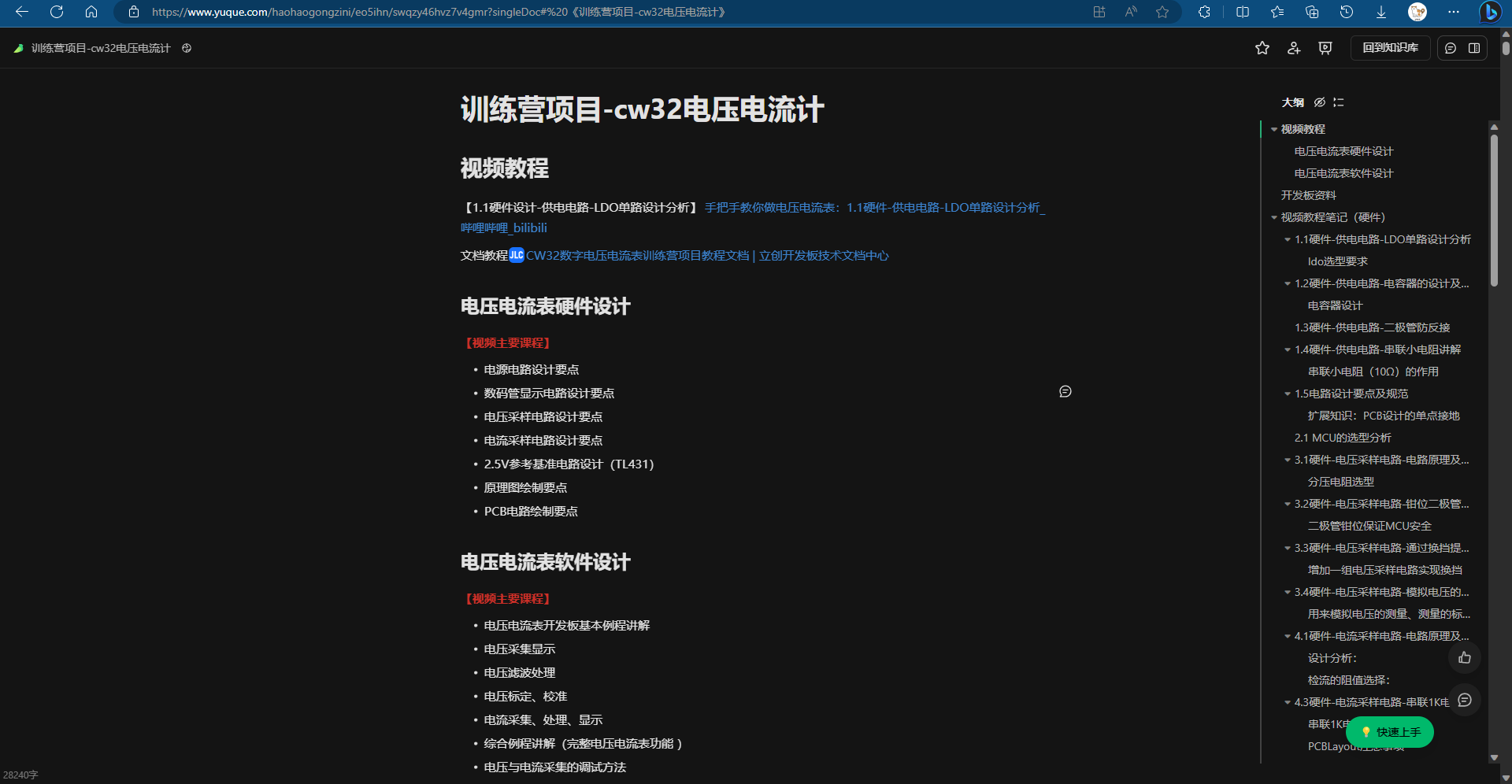
) 3. Documentation: CW32 Digital Voltage and Current Meter Training Camp Project Tutorial Document | LCSC Development Board Technical Document Center (lckfb.com)
4. Bilibili Video Materials: Step-by-Step Guide to Making a Voltage and Current Meter: 1.1 Hardware - Power Supply Circuit - LDO Single-Channel Design Analysis_Bilibili_bilibili
4. Author's Own Notes: Yuque Document Address (Added some of my own, step-by-step from hardware to software)
5. Official Project: LCSC·Diwenxing CW32 Digital Voltage and Current Meter Expansion Board
...
Principle Explanation (See Documentation for Details)
1. Power Supply Circuit SE8550K2
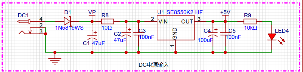
LDO (Low Dropout Linear Regulator) Selection: This project uses an LDO as the power supply. Considering that most voltmeter products are used in industrial scenarios with 24V or 36V power supplies, the SE8550K2 with a maximum input voltage of 40V was selected. The main reason for not using a DC-DC step-down circuit to handle the large voltage drop is to avoid introducing DC-DC ripple interference during the design process; a secondary reason is to reduce project costs.
2. MCU Control: CW32 M0
Selection Should Not Be Blind: When selecting the MCU (Microcontroller Unit) for this project, multiple aspects need to be considered to ensure that the selected MCU meets the project requirements.
Clearly define your project requirements: Clearly understand how much computing power the project needs, including clock speed, processor core type, and whether a floating-point unit is required.
Clearly define the required I/O ports and important peripherals, such as ADC peripherals. Since this project is a development board project, the main purpose is debugging and learning; therefore, there are no strict limitations on the number of I/O ports: i.e., the cost associated with it is not considered.
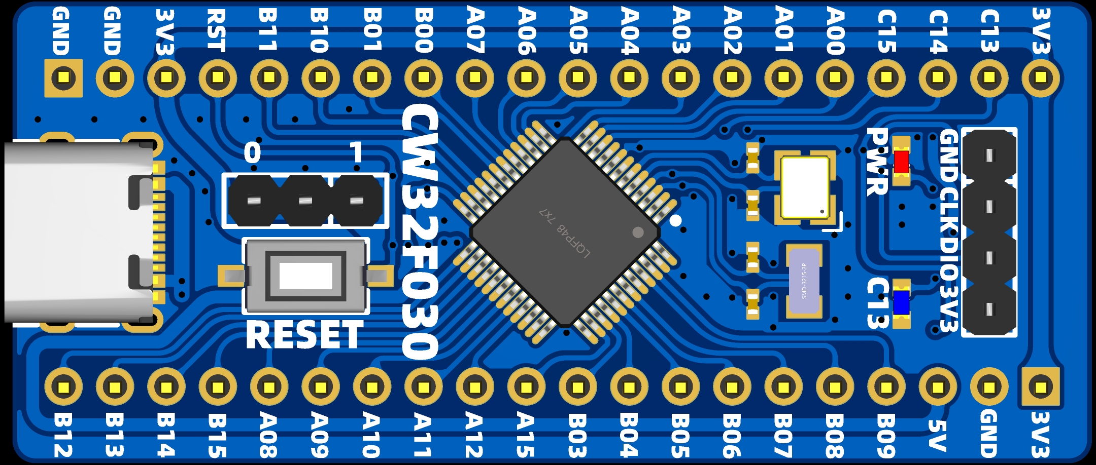
Remember to match the correct port
3. Voltage sampling.
The voltage ratio of the resistor is 220K+10K. The voltage divider resistor in this project is 22:1 (ADC_IN11).
The voltage divider resistor
is selected to measure the maximum voltage. For safety reasons, this project uses 30V (the actual maximum can be displayed as 99.9V or 100V).
The ADC reference voltage is 1.5V in this project, and this reference voltage can be configured through the program.
To reduce power consumption in the sampling circuit, the low-side resistor (R7) is typically chosen as 10K based on experience.
The high-side resistance of the voltage divider can then be calculated using the above parameters.
The required voltage division ratio is calculated as follows: ADC reference voltage: Design input voltage, calculated as 1.5V/30V = 0.05 using known parameters.
High-side resistance: Low-side resistance/voltage division ratio, calculated as 10K/0.05 = 200K using known parameters.
A standard resistor is selected: A resistor slightly higher than the calculated value of 200K is chosen. We typically choose E24 series resistors; therefore, in this project, 220K is chosen, which is greater than 200K and closest to the calculated value.
If, in actual use, the voltage to be measured is lower than 2/3 of the module's design voltage (66V), the voltage divider resistor can be replaced and the program modified to improve measurement accuracy. An example is provided below:
Assuming the measured voltage is no higher than 24V, and other parameters remain unchanged .
Calculations show that 1.5V/24V = 0.0625, and 10K/0.0625 = 160K. 160K is a standard E24 resistor and can be directly selected. Alternatively, a higher resistance value of 180K can be chosen to allow for some redundancy.
In practical applications, if the voltage to be measured is higher than the module's design voltage of 99V, the voltage divider resistor can be replaced, or the reference voltage can be modified to achieve a larger voltage measurement range. The following example illustrates this:
Assuming the measured voltage is 160V, the solution is to increase the voltage reference to expand the range.
Given that the voltage division ratio of the selected resistor is 0.0145, we can calculate 160V * 0.0145 = 2.32V using the formula. Therefore, we can choose a 2.5V voltage reference to increase the range (increasing the range will reduce accuracy).
Considering the potential fluctuations in the measured power supply, a 10nF filter capacitor is connected in parallel with the low-side voltage divider resistor in the circuit design to improve measurement stability. In this project, an additional voltage sampling circuit was
added
. Therefore, we can discuss the significance of range switching in improving measurement accuracy. To achieve more accurate measurements, multimeters often have multiple range settings. By adjusting different ranges, the optimal measurement accuracy of the measured point within the corresponding range can be obtained.
This project requires a combination of hardware and software to implement this function. When we first use the ADC_IN11 channel mentioned earlier to measure voltages below 30V, if the measured voltage is within 0~3V, then we use the ADC_IN9 channel for measurement. At this time, due to the reduced voltage division ratio, the measurement accuracy is greatly improved. There are many ways to implement range switching, and the development board design provides more design possibilities.

4. Current Sampling Current flow voltage division with small resistors.
This project uses a low-side current sampling circuit for current detection. When learning the common ground between the low-side of the sampling circuit and the development board's meter interface, please do not solder R0!!!

The design analysis
for this project involves a sampling current of 3A, and the selected sampling resistor (R0) is 100mΩ. The selection of the sampling resistor mainly needs to consider the following aspects:
the maximum value of the pre-designed measurement current;
the voltage difference caused by the 3A current sensing resistor in this project; and
the power dissipation of the current sensing resistor, which should generally not exceed 0.5V. A suitable package should be selected based on this parameter. Considering the power dissipation (temperature) issue under high current, a 1W metal wire-wound resistor package was chosen
. The voltage amplification factor across the current sensing resistor is also important. Since no operational amplifier is used to build the amplification circuit in this project, the factor is 1.
The current sensing resistor value can then be calculated using the above parameters
. Since no amplifier circuit is used, a larger sampling resistor is needed to obtain a higher measured voltage for measurement.
Considering that a larger resistor would result in a larger voltage drop and higher power consumption, an unlimited selection of a larger resistor is not feasible.
This project uses a 1W package resistor, corresponding to a temperature rise power of 1W.
Based on the above data, a 100mΩ current sensing resistor was selected for this project. According to the formula, 3A * 100mΩ = 300mV, 900mW can be calculated.
To cope with different operating environments, especially high current scenarios, the R0 resistor can be replaced with constantan wire or a shunt. The replacement can be selected according to the actual application scenario. For safety and educational purposes, this project will not discuss measurements exceeding 3A in detail, but the principle is the same.
5. Digital Tube Common cathode digital tube (direct microcontroller port, shift register see temperature and humidity meter project)
This project uses a digital tube as the display unit.
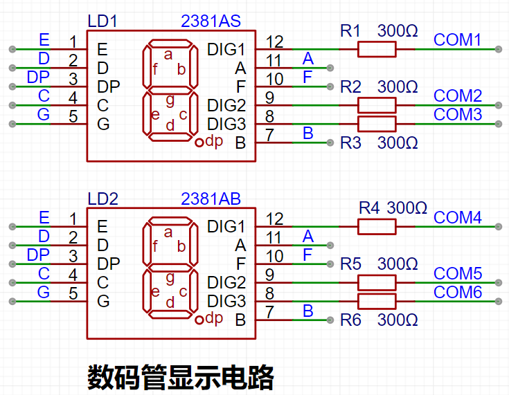
This project uses two 0.28-inch three-digit common-cathode LED displays as the display device. Compared to a display screen, LED displays offer better visibility in complex environments. The brightness of the LED displays can be increased by using smaller current-limiting resistors, depending on the specific needs of the application environment. Furthermore, LED displays have better mechanical properties and are not as easily damaged by external forces as display screens. They are widely used in industrial applications where stability and reliability are crucial. From a development board learning perspective, this makes it easier to learn electronic measurement principles and related development in a targeted manner.
In this project, actual testing showed that the current-limiting resistors (R1~R6) for the LED displays were configured to 300Ω. The corresponding brightness for both red and blue LED displays was good and the brightness was soft and not glaring.
Strictly speaking, the current-limiting resistors should be added to the segments; adding them to the digits would affect the display effect. Our actual design places them in the digits to save a few resistors, but the impact on the display is not significant. Therefore, we add them to the digits for convenience.
The
driving principle of LED displays mainly involves controlling the switching state of each segment of the LED display to display numbers, letters, or symbols. The following is a detailed explanation of the driving principle:
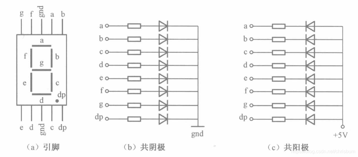
Basic Structure of a Digital Tube:
A digital tube typically consists of seven or eight LED segments (eight segments in this project). Each segment represents a part of the digital tube and can display numbers 0-9, letters AF, etc.
Digital tubes come in two types: common cathode and common anode. The difference lies in whether the common terminal COM (the end connecting all LEDs) is connected to the negative or positive terminal of the power supply.
Driving Methods:
Segment Selection: The desired number or character is displayed by controlling the on/off state of each segment of the digital tube. Each segment corresponds to a control signal; when the control signal is on, the segment lights up, and vice versa. (a, b, c, d, e, f, g, dp)
Bit Selection: The digital tube to be displayed is selected by controlling the bit lines of the digital tube. Bit line control sets the bit line of the digital tube to be displayed to a high level, and the bit lines of other digital tubes to a low level. By continuously switching the state of the bit lines, the display switching between multiple digital tubes can be achieved.
Driving Circuit:
The driving circuit for a digital tube can be implemented using hardware circuits, such as integrated circuits like digital signal processors (DSPs), microcontrollers (MCUs), or shift registers, to generate control signals suitable for the LEDs.
These control signals can be in the form of pulse width modulation (PWM) signals, serial data signals, etc. By controlling the frequency, width, and amplitude of these signals, the brightness of the digital tube can be controlled, thereby displaying the desired numbers or letters.
Software Control:
In addition to hardware driving circuits, the driving of digital tubes can also be implemented through software control. By programming to generate control signals suitable for the digital tubes, more flexible and complex display effects can be achieved, such as scrolling or alternating display of numbers.
Driving Common Cathode and Common Anode Digital Tubes:
For common cathode digital tubes, the common cathode pin is connected to the negative terminal of the power supply, and the control pin is connected to the output pin of the control chip. When a certain number needs to be displayed, the control chip outputs the corresponding encoded signal to the control pin, causing the corresponding LED segment to light up.
For common-anode seven-segment displays, the working principle is similar to that of common-cathode seven-segment displays, except that the common-anode pin is connected to the positive terminal of the power supply, and the control pin is connected to the output pin of the control chip.
Encoding Display:
To display the corresponding number or character on the seven-segment display, the segment data port must output the corresponding character encoding. For example, to display the number "0", the character encoding for a common-anode seven-segment display is 11000000B (i.e., C0H), while the character encoding for a common-cathode seven-segment display is 00111111B (i.e., 3FH). The specific encoding depends on the actual seven-segment display.
Dynamic and Static Display:
Seven-segment displays can use either static or dynamic display methods. In static display, each of the eight segments of each seven-segment display is connected to an 8-bit I/O port address. As long as the I/O port outputs a segment code, the corresponding character is displayed and remains unchanged. Dynamic display, on the other hand, lights up each segment of the seven-segment display one by one in turn, achieving simultaneous visual display through rapid switching.
In summary, the driving principle of a digital tube displays (STU) is to control the switching state of each LED segment to display numbers, letters, or symbols, and to switch between multiple STUs through segment selection and digit selection. The driving of the STU can be achieved through hardware circuitry or software control, and common cathode or common anode STUs can be selected as needed.
This project actually uses dynamic scanning display to drive the STU.
Calculating the required current:
Since this project uses dynamic scanning display, at any given time, only a maximum of 8 segments (or LEDs) can be lit, or in other words, only one digit can be lit. According to the design, the required driving current is approximately 11mA (IO port high-level voltage 3.3V ÷ 300Ω).
At this point, it is important to ensure that the selected MCU has sufficient current-source/current-sinking capability.
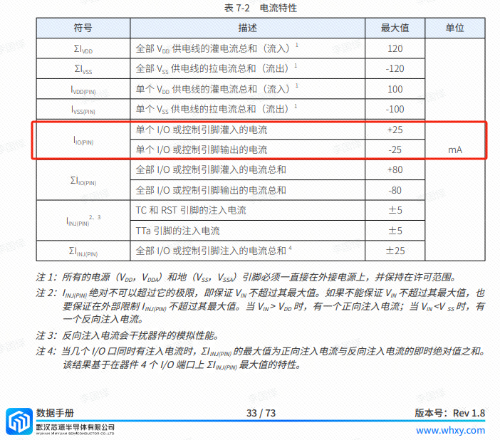
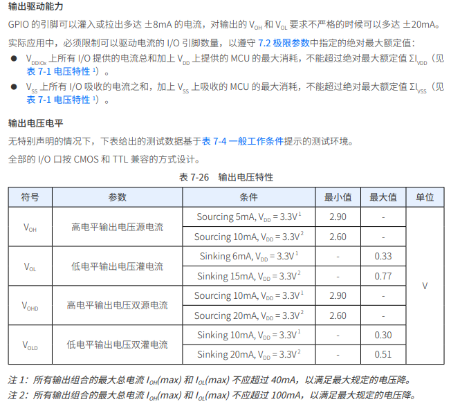
Analysis of the datasheet indicates that the CW32 is suitable. (Some chips are not compatible)
6. Power Indicator and Working Indicator

7. Button Circuit Ordinary Buttons

8. Reference Voltage TL431
This project adds an extra TL431 circuit to provide a 2.5V reference voltage, which can be used to provide an external voltage reference for calibrating the ADC. From a product design perspective, due to the inherent ADC performance advantages of the CW32, this circuit is not necessary. This circuit is designed on the development board to learn the relevant application principles. The
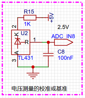
TL431 is a relatively "old" device, very classic, and widely used; it is still found in many electronic products.
Many beginners may be encountering this device for the first time, so we will briefly explain the principles of this product to help everyone better apply the TL431.
TI defines it as a precision programmable reference in its name. On the first page of the references, we can focus on several key characteristics.
Precision: Precision indicates that its output voltage is very accurate. I used a ±0.5% accuracy TL431, which measured 2.495V on the board at room temperature. Compared to common Zener diodes, the accuracy is vastly different. In the application circuit diagram, the TL431 is represented by a Zener diode symbol.
Adjustable output voltage: The adjustable output voltage is between Vref and 36V. In our project, we use the output Vref voltage. Vref voltage is approximately 2.5V. Therefore, we use 2.5V in the description, which is approximately equal to 36V.
Sinking current capability: This refers to how much current the output voltage pin can provide. This is greatly related to the resistance value (R13) in the application circuit. It should not be less than 1mA. If there is no need for sinking current, do not design the current too high, causing unnecessary power consumption.
...
PCB design (see document for details)
1. The official documentation is very detailed
. ...
Software
1. The official documentation is very detailed
main.c
#include "main.h"
#include "Seg_Dis.h"
#include "BTIM1.h"
#include "ADC.h"
#include "flash".h"
extern uint16_t Volt_Buffer[ADC_SAMPLE_SIZE];
extern uint16_t Curr_Buffer[ADC_SAMPLE_SIZE];
extern uint8_t Seg_Reg[6];
uint16_t V_Buffer,I_Buffer;
unsigned int spp_start=0;
uint32_t ble_time=0;
unsigned int timecount=0;
//5V and 15V calibration
unsigned int X05=0;
unsigned int X15=0;
unsigned int Y15=15;
unsigned int Y05=5;
float K; //slope
//0.5A and 1.5A calibration
unsigned int IX05=0;
unsigned int IX15=0; unsigned
int IY15=150;
unsigned int IY05=50;
float KI; //slope
//defining mode
unsigned char Mode=0;
//mode0 :Voltage and current normal display mode
//mode1 :Voltage 5V calibration
//mode2 :Voltage 15V calibration
//mode3 : Current 0.5A calibration
// mode4 : Current 1.5A calibration
unsigned char BrushFlag=0;
void RCC1_Configuration(void)
{
FLASH_SetLatency(FLASH_Latency_2); // Set the main frequency to 48MHz. Note that the access cycle of the FLASH needs to be changed to FLASH_Latency_2.
RCC_HSI_Enable(RCC_HSIOSC_DIV1); // Set the frequency to 48MHz
RCC_SYSCLKSRC_Config(RCC_SYSCLKSRC_HSI); // Select the SYSCLK clock source 48MHz
RCC_HCLKPRS_Config(RCC_HCLK_DIV1); // Configure the division factor from SYSTICK to HCLK 48MHz
RCC_PCLKPRS_Config(RCC_PCLK_DIV8); // Configure the division factor from HCLK to PCLK 6MHz
InitTick(48000000); // The SYSTICK operates at a frequency of 48MHz, interrupting once every ms
}
void RCC_Configuration(void)
{
/* 0. Enable and calibrate HSI */
RCC_HSI_Enable(RCC_HSIOSC_DIV6);
/* 1. Set the division factor for HCLK and PCLK */
RCC_HCLKPRS_Config(RCC_HCLK_DIV1);
RCC_PCLKPRS_Config(RCC_PCLK_DIV1);
/* 2. Enable PLL, multiply the frequency to 64MHz via PLL */
RCC_PLL_Enable(RCC_PLLSOURCE_HSI, 8000000, 6); // HSI default output frequency 8MHz
// RCC_PLL_OUT(); // Output PLL clock on PC13 pin
///
///
__RCC_FLASH_CLK_ENABLE();
FLASH_SetLatency(FLASH_Latency_3);
/* 3. Switch the clock to PLL */
RCC_SysClk_Switch(RCC_SYSCLKSRC_PLL);
RCC_SystemCoreClockUpdate(48000000);
RCC_PCLKPRS_Config(RCC_PCLK_DIV8); // Configure HCLK The frequency divider to PCLK is 6MHz.
}
void KEYGPIO_Init(void)
{
__RCC_GPIOB_CLK_ENABLE();//Enable the clock for GPIOB
__RCC_GPIOC_CLK_ENABLE();//Enable the clock for GPIOC
GPIO_InitTypeDef GPIO_InitStruct;
GPIO_InitStruct.Pins = GPIO_PIN_12|GPIO_PIN_13|GPIO_PIN_14; //
GPIO_InitStruct.Mode = GPIO_MODE_INPUT_PULLUP;
GPIO_InitStruct.IT = GPIO_IT_NONE;
GPIO_InitStruct.Speed = GPIO_SPEED_HIGH;
GPIO_Init(CW_GPIOB, &GPIO_InitStruct);
GPIO_InitStruct.Pins = GPIO_PIN_13; //
GPIO_InitStruct.Mode = GPIO_MODE_OUTPUT_PP;
GPIO_Init(CW_GPIOC, &GPIO_InitStruct);
}
extern void DisplaySETV(uint32_t value);
void DisplayBuff(void)
{
if(Mode==0)
{
Display(V_Buffer);
if(I_Buffer>400)I_Buffer=400;
DisplayI(I_Buffer);
}
else if(Mode==1) //S.05.
{
Seg_Reg[0] =5+10;
Seg_Reg[1] =0;
Seg_Reg[2]=5+10;
DisplaySETV(V_Buffer);
}
else if(Mode==2) //S.15.
{
Seg_Reg[0] =5+10;
Seg_Reg[1] =1;
Seg_Reg[2]=5+10;
DisplaySETV(V_Buffer);
}
else if(Mode==3) //A.0.5
{
Seg_Reg[0] =20;
Seg_Reg[1] =0+10;
Seg_Reg[2]=5;
DisplayI(I_Buffer);
}
else if(Mode==4) //A.1.5
{
Seg_Reg[0] =20;
Seg_Reg[1] =1+10;
Seg_Reg[2]=5;
DisplayI(I_Buffer);
}
}
void ComputeK(void)
{ K =
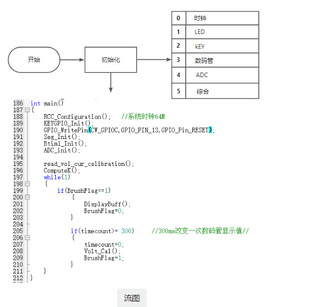
(Y15-Y05); K=K/(X15-X05) ; KI=(IY15 - IY05 ) ; da[0]=0xaa; da[1]=X05; da[2]=X15; da[3]=IX05; da[4]=IX15; flash_erase(); flash_write(0,da,5); } /** * @brief * */ void read_vol_cur_calibration(void) { uint16_t da[5]; flash_read(0,da, 5); if(da[0]!=0xaa)//If it hasn't been calibrated yet, calculate the theoretical value and store it { X15=15.0/23/1.5*4096; X05=5.0/23/1.5*4096; IX05=0.5*0.1/1.5*4096; IX15=1.5*0.1/1.5*4096; save_calibration(); } else { X05=da[1]; X15=da[2]; IX05=da[3]; IX15=da[4]; } } void Volt_Cal(void); int main() { RCC_Configuration(); //System clock 64M KEYGPIO_Init(); GPIO_WritePin(CW_GPIOC,GPIO_PIN_13,GPIO_Pin_RESET); Seg_Init(); Btim1_Init(); ADC_init(); read_vol_cur_calibration(); ComputeK(); while(1) { if(BrushFlag==1) { DisplayBuff(); BrushFlag=0; } if(timecount>= 300) //Change the digital tube display value once every 300ms// { timecount=0; Volt_Cal(); BrushFlag=1; } } } uint32_t Mean_Value_Filter(uint16_t *value, uint32_t size) //Mean filtering { uint32_t sum = 0; uint16_t max = 0; uint16_t min = 0xffff; int i; for(i = 0; i { sum += value[i]; if(value[i] > max) { max = value[i];
}
if(value[i]
{
min = value[i];
}
}
sum -= max + min;
sum = sum / (size - 2);
//if(sum>1)sum+=4; Post-calibration
return sum;
}
void Volt_Cal(void)
{
float t,KT1;
V_Buffer = Mean_Value_Filter(Volt_Buffer,ADC_SAMPLE_SIZE);//Use mean filtering
I_Buffer = Mean_Value_Filter(Curr_Buffer,ADC_SAMPLE_SIZE); //Use mean filtering
if(V_Buffer>=X05)
{
t=V_Buffer-X05;
V_Buffer=(K*t+Y05)*1000;}
else
{
KT1=5000;
KT1=KT1/X05;
V_Buffer=KT1*V_Buffer;
}
// Rounding
if(V_Buffer % 10 >= 5)
{
V_Buffer = V_Buffer / 10 + 1; //10mV is the unit
}
else
{
V_Buffer = V_Buffer / 10;
}
if(I_Buffer>=IX05)
{
t=I_Buffer-IX05;
I_Buffer=(KI*t+IY05)*10;
}
else
{
KT1=500;
KT1=KT1/IX05;
I_Buffer=KT1*I_Buffer;
}
if(I_Buffer % 10 >= 5)
{
I_Buffer = I_Buffer / 10 + 1;
}
else
{
I_Buffer = I_Buffer / 10;
}
//I_Buffer=I_Buffer * ADC_REF_VALUE >> 12;
/**
mv =I_Buffer * ADC_REF_VALUE >> 12,
R = 100mr,
10ma = mv/R/10=mv/0.1/10 = mv
*/
}
void BTIM1_IRQHandler(void)
{
static uint32_t keytime=0,keytime2=0,keytime3=0,ledcount=0;
/* USER CODE BEGIN */
if (BTIM_GetITStatus(CW_BTIM1, BTIM_IT_OV))
{
BTIM_ClearITPendingBit(CW_BTIM1, BTIM_IT_OV);
Get_ADC_Value();
ledcount++; //LED flashing
if(ledcount>=1000)
{PC13_TOG();ledcount=0;}
timecount++;
Dis_Refresh();//digital tube scanning display
if(GPIO_ReadPin(CW_GPIOB,GPIO_PIN_12)==GPIO_Pin_RESET)
{
keytime++;
if(keytime>=100 )
{
keytime=0; //switch mode
Mode++;
if(Mode>=5)Mode=0;
BrushFlag=1; // Update the digital tube
}
}
else keytime=0;
if(GPIO_ReadPin(CW_GPIOB,GPIO_PIN_13)==GPIO_Pin_RESET&&Mode!=0)
{
keytime2++;
if(keytime2>=100 )
{
keytime2=0; // Switch mode
if(Mode==1)
{
X05=Mean_Value_Filter(Volt_Buffer,ADC_SAMPLE_SIZE);
save_calibration();ComputeK();Volt_Cal();BrushFlag=1;Mode=0;
}
if ( Mode == 2 )
{ save_calibration();ComputeK();Volt_Cal();BrushFlag=1;Mode=0; } if(Mode==4) { IX15=Mean_Value_Filter(Curr_Buffer,ADC_SAMPLE_SIZE); save_calibration();ComputeK();Volt_Cal();BrushFlag=1;Mode=0; } } } else keytime2=0; if(GPIO_ReadPin(CW_GPIOB,GPIO_PIN_13)==GPIO_Pin_RESET) { keytime3++; if(keytime3>=100 ) { keytime3=0; //Switch mode Mode=0; BrushFlag=1; //Update digital tube } } else keytime3=0; } /* USER CODE END */ } ..Problems encountered: 1. The source code downloaded from the official website, after adjusting the compilation environment V5.06 and confirming activation, correct version, no code modification, and correct path, still shows the error "cmsis_version.h not found" (as shown in the picture below). This may be because the CMSIS firmware is too old. Update it. The firmware is attached: ARM.CMSIS.5.9.0.pack 2. Measure the size of the banana plug to prevent it from not fitting. My first version was slightly off in size. It is recommended to increase the diameter by 0.2CM, such as in V1.1 3. The operation process is shown in my V1.1 silkscreen ... Buy, buy, buy! 1. LCSC Mall (use 16-15mm batteries wisely, they're enough) 2. Taobao [Taobao] https://m.tb.cn/h.gOiMK9fGGU9G6cX?tk=yMCK3VkxsKW MF6563 "5 x 4mm lantern head banana plug socket terminals male and female plug-in power test terminals female plug" Click the link to open directly or search on Taobao to open directly 3. [Taobao] https://m.tb.cn/h.gOiosFkG74O7PQ9?tk=RDeJ3VkDlEE CZ0002 "Dayi alloy resistor 2512/2W/3W 1%" 0.033R-0.2R/RLP25FEGR033-R200" Click the link to open directly or search on Taobao. 4. [Taobao] https://m.tb.cn/h.gOiL1LAF1qzPgGD?tk=Alt93VkDOB3 HU9196 "~DC power plug socket male and female connector adapter female and male 5.5-2.1/2.5mm 3.5 round hole (~@ ~)" Click the link to open directly or search on Taobao . Finally, thanks to LCSC EDA, thanks to Sinyuan Semiconductor, thanks to LCSC development board, and thanks to LCSC Mall.

Thanks to LCSC Development Board - Developer Jun, Sinyuan Semiconductor - Engineer Li, and LCSC Development Board - Li Guoyi.
See you next time!


 京公网安备 11010802033920号

 BSTS-221-D-B-20-T-120


