I previously bought a top-selling breadboard power supply from Taobao, but it only offered micro USB and DC ports, and its size was a bit too large. So I made this miniature power module,
using the most common Type-C interface, providing 5V and 3.3V outputs, which can be switched via a switch.
Several improvements were made to the initial version of the STC competition project: https://oshwhub.com/loveliang/stc8h8k64u-minimum-system
I. Welding Process Precautions (
3D Preview).

Below is a welding preview;
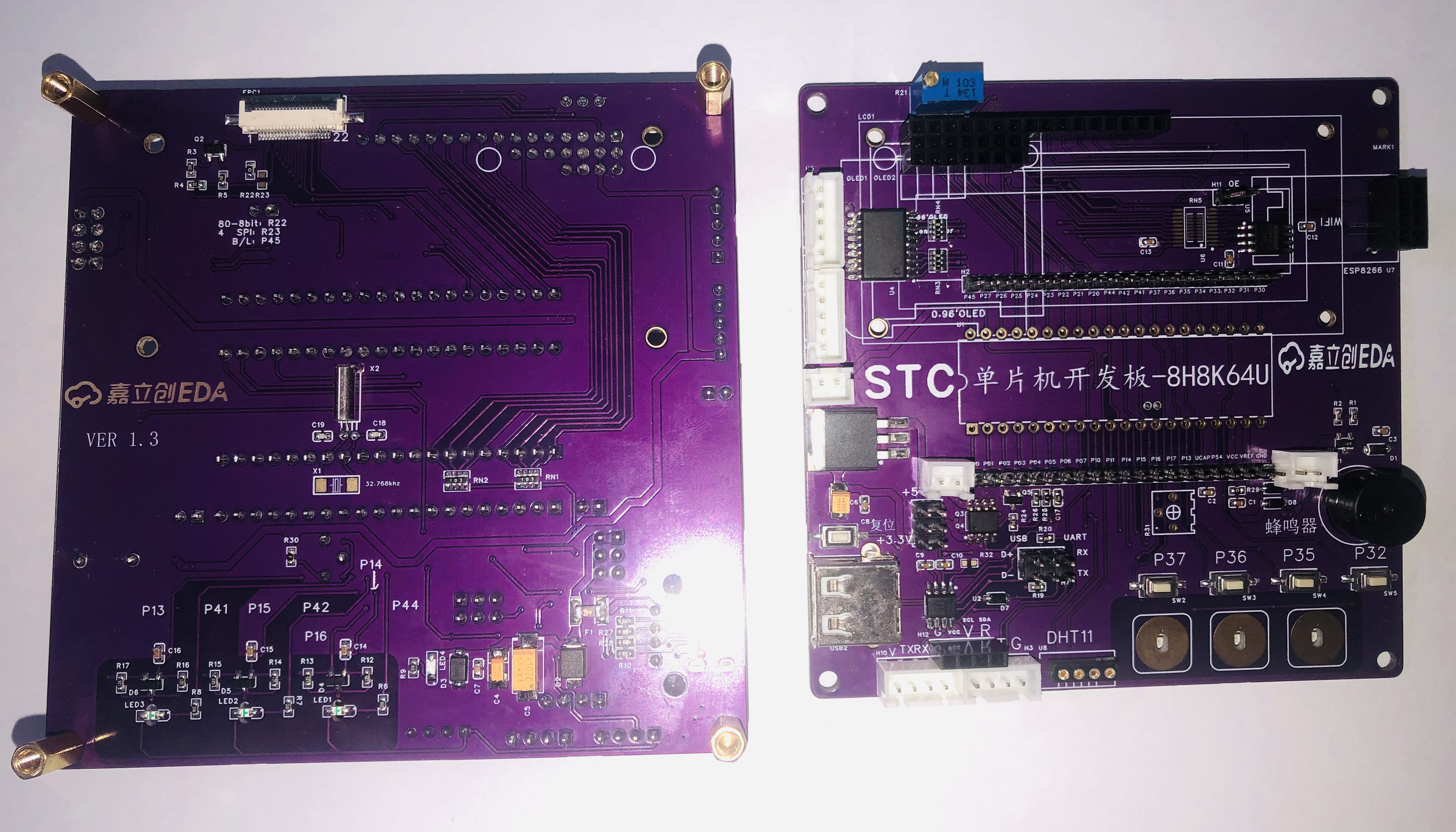
the default is 5V welding. If you choose 3.3V, please note the following:
5V: Cut RN5 in the middle and weld U6.
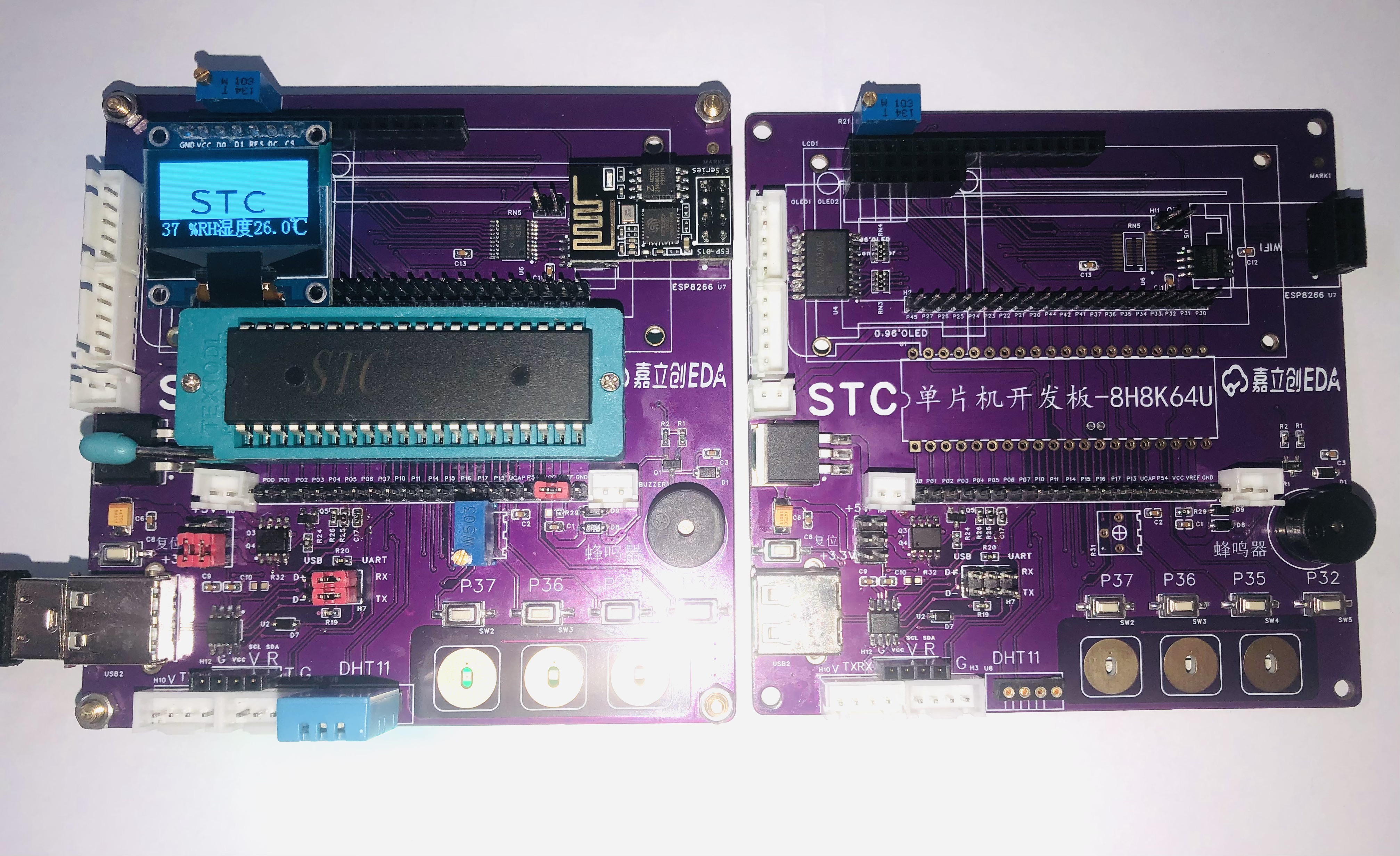
The U8 position is convenient for inserting and removing sensor experiments. The DS18B20/infrared/DHT11 module has been changed to a round hole socket.
3.3V: If you always use 3.3V, you can omit U6 and RN5 does not need to be cut in the middle (it is already shorted by wiring).
An FPC LCD display socket is provided; selective welding (bottom layer) is possible if needed.
The power supply interface also provides a TYPE-C interface; if your soldering skills are not solid, you can choose to weld a USB-A, or both can coexist.
Serial ports P30 and P31 are also brought out separately for convenient serial port experiments and for downloading programs to the microcontroller using your own serial port module.
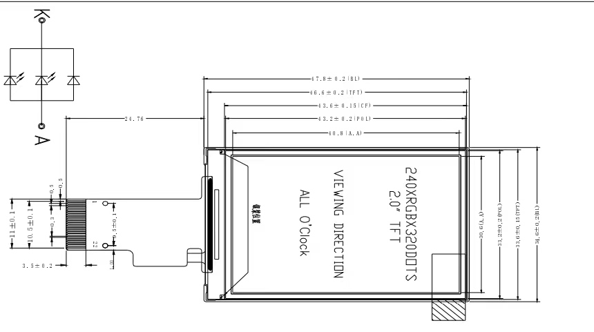
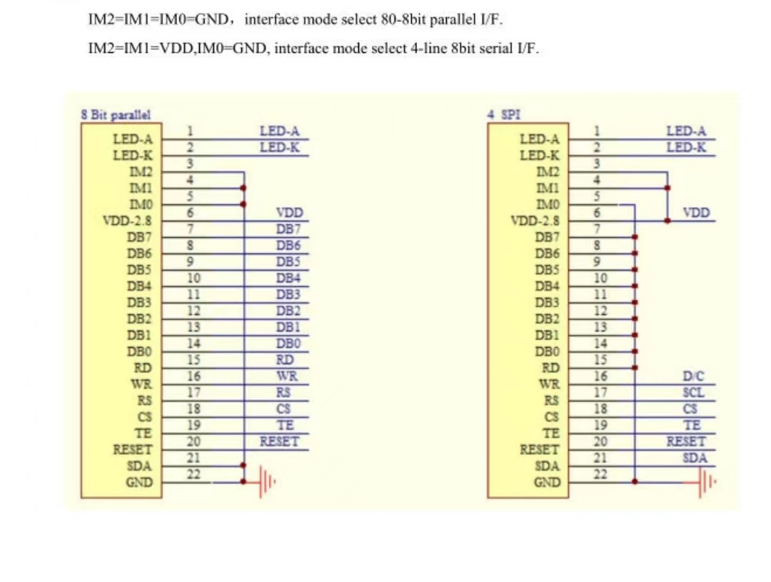
The LCD screen uses a 22P standard interface. As shown in the diagram below
, the second step is to download the program
using the latest STC-ISP software from the official STC company. The default settings are as follows

: select 35MHz for the crystal oscillator. Then confirm the jumper caps are correct as shown in the diagram below.

Download directly using the STC serial port chip.
If using HID download, disconnect the shorting cap on the right side of H6, and move all H7 to the USB end.
First, press and hold SW5 (P32), then press the reset button and power on again. The following image will appear:

Scan the serial port; if "HID" appears, release SW5, open the file, and download.
The third step is program testing
. After soldering, you can download the OLED test program I provided. The source code is not provided here; it's the same as the previous version. Please go to: https://oshwhub.com/loveliang/stc8h8k64u-minimum-system to download
the OLED: 0.96-inch, SPI 7-pin, SSD1306 control chip.
The fourth step involves some I/O ports being combined for easier use of hardware I2C and SPI, requiring both software and hardware driver options. Explore
the already lit 480*320 TFT display screen; for the effect, please visit the STC forum: https://www.stcaimcu.com/forum.php?mod=viewthread&tid=9310
V. STC Serial Port Chip:
The ISP software can create serial port chips;
if you don't want to use a serial port, it can be used as a microcontroller to achieve communication between two microcontrollers, or to power an OLED (with an IIC interface H12 already installed).
Hardware solution for Problem A of the 2024 Electronic Engineering Contest – Hubei Province First Prize, P07
The hardware solution that won first place in Hubei Province for Problem A of the 2024 National Electronic Design Contest has a combined weight of 560g and a single-machine efficiency of 98.9%.
As we all know, this year's Problem A relies on
the extremely complex AC-AC direct conversion, parallel connection of two machines without communication, and strange weight...
Let's get to the point:


Careful analysis of the problem reveals its core requirements:
1. AC-AC conversion, AC-DC-AC conversion prohibited
. 2. Droop current sharing (the two machines are only connected by power lines, i.e., communication is prohibited).
Upon closer observation, we find that the output voltage is always lower than the input voltage
. Therefore, we should build a buck-type AC-AC converter.
With a general direction (a buck-type AC-AC converter with droop control), we can search for relevant papers to find topologies and control methods.
Three topologies are suitable for our approach:
1. Folded bridge
: The AC input is folded into a pseudo-DC "bun" wave by a full-bridge converter, then inverted by a full-bridge converter to generate a sine wave.
The hardware architecture of this scheme is very simple, basically following the AC-DC-AC method.
However, after careful consideration, the "bun" wave seems too risky. If the reviewer thinks it's DC, it will be rejected.
Therefore, folded bridge, OUT!
2. AC using a bidirectional switch. Buck
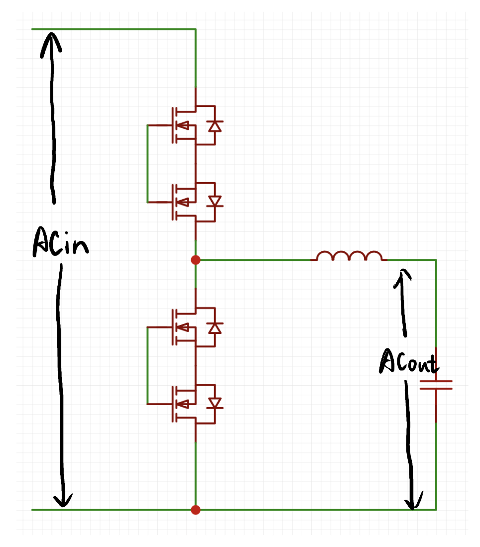
uses back-to-back MOSFETs as bidirectional switches to replace the MOSFETs in ordinary buck converters, making it a bidirectional buck converter .
It can work normally in both the positive and negative half-cycles of AC, achieving the function of step-down.
However, bidirectional switches require isolated MOSFET drivers and isolated power supplies. We did not make the corresponding module
bidirectional buck converter beforehand, so it's out!
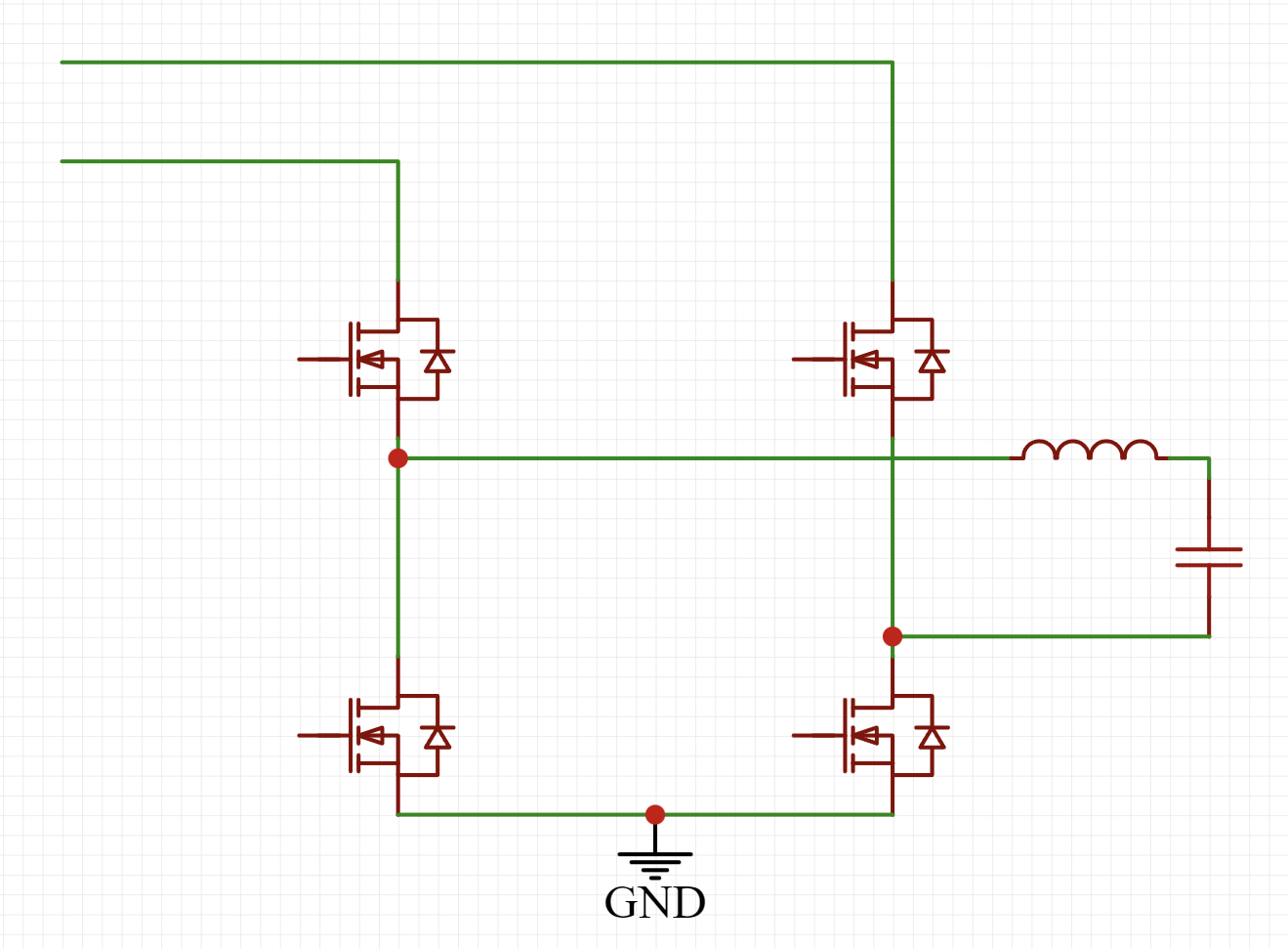
3. I'm too lazy to analyze the AC buck converter using ordinary half-bridge

. Once you
have the topology, you can consider the architecture of the entire system.
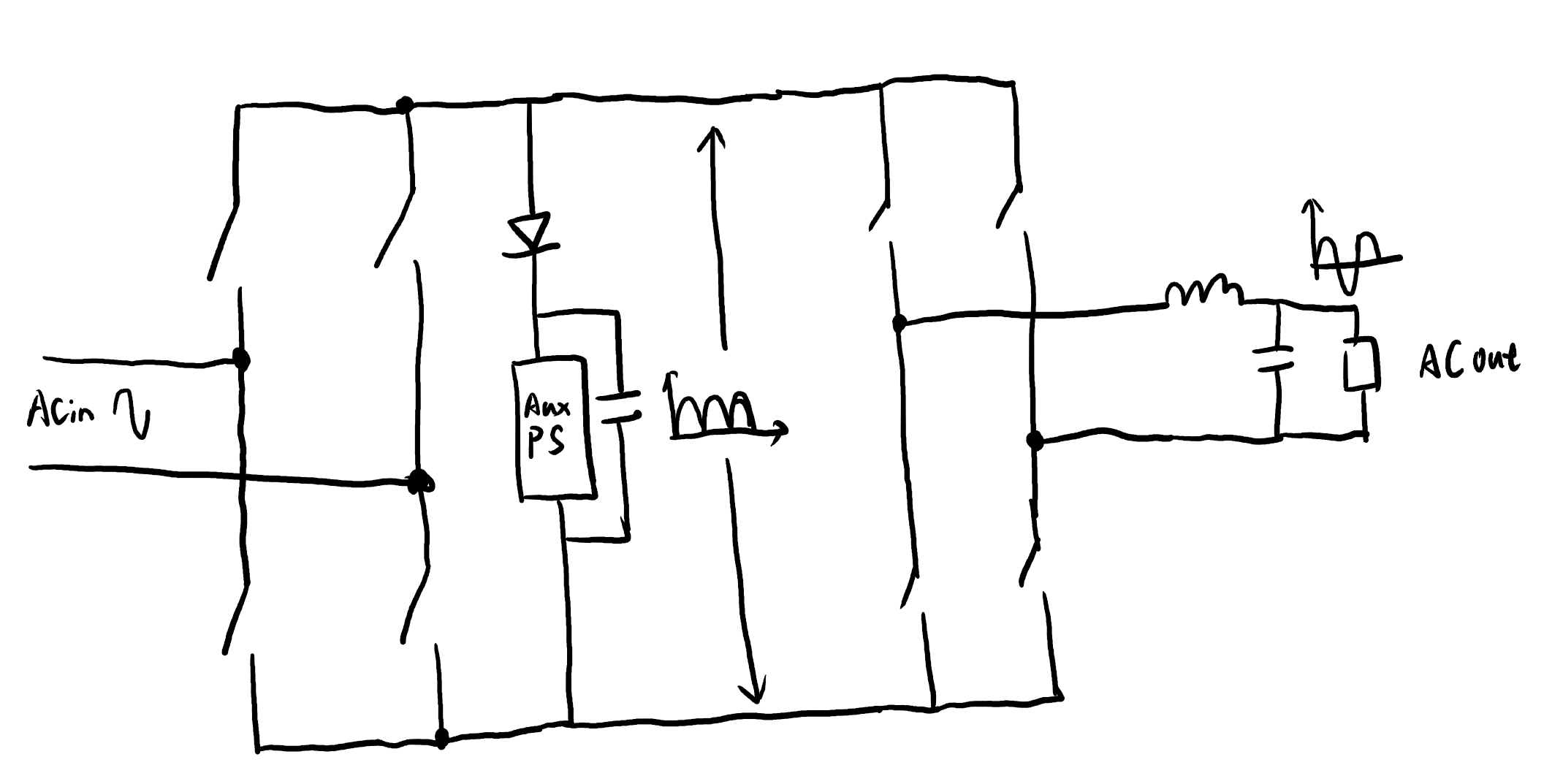
First, how should the auxiliary power be placed?
Since our auxiliary power is non-isolated, we must first determine the ground of the entire system
. We take the common ground of the two half-bridges as the system ground. We can see that the entire system becomes like this:
Isn't it clear at a glance?
So, regarding the placement and power supply of the non-isolated auxiliary power supply, I'll only provide this diagram here:

the red and blue arrows represent the current paths. You'll understand once you figure it out.
Next, regarding the measurement setup:
the quantities to be measured are input voltage, output voltage, and output current.
The input voltage is used for software phase-locked loop, the output voltage for the voltage loop, and the output current for the droop control loop.
This is simply based on the existing modules; it's very straightforward.
Finally, the control card:
it also uses the ground above as ground and the auxiliary power supply output as power. Just solder it on, and you're done.
Therefore, the hardware framework of the entire system is as follows:

Hardware Selection:
Don't look at this; it's just something I've done before... The remaining/inherited modules from this project, with all schematics open source, are too lazy to analyze (don't want to write an article QAQ).
Based on this, we optimized the layout to make it as compact as possible, and ultimately achieved a total weight of 560g for both machines.
Other specifications were basically met, resulting in first place in Hubei Province's A-level problem (doge).
Hint:
We used a gallium nitride half-bridge (six-layer board) for prototyping at JLC. Using a free coupon, we couldn't pass the review. Customer service said the board was too simple, with large copper surfaces on the inner layers, and suggested paying extra for a four-layer thick copper board. However, the 2oz surface copper thickness couldn't meet the minimum line width and spacing requirements.
As for whether this board is simple or not, you'll know the answer after seeing it.
Man, what can I say!
JLC OUT!
PDF_2024 Electronic Engineering Contest Problem A Hardware Solution - Hubei Province First Prize P07.zip
Altium_2024 Electronic Engineering Contest Problem A Hardware Solution - Hubei Province First Prize P07.zip
PADS_2024 Electronic Engineering Contest Problem A Hardware Solution - Hubei Province First Prize P07.zip
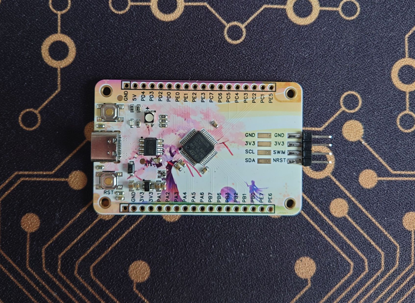
This is a standard STM8S005C6T6 development board, which can be used with another project, STLINK V2.
I won a colored silkscreened coupon in a points lottery, so I added some decorations.
PDF_STM8S005C6T6 Development Board & Color Silkscreen & Thor.zip
Altium_STM8S005C6T6 Development Board & Color Silkscreen & Thor.zip
PADS_STM8S005C6T6 Development Board & Color Silkscreen & Thor.zip
BOM_STM8S005C6T6 Development Board & Color Silkscreen & Thor.xlsx
93244
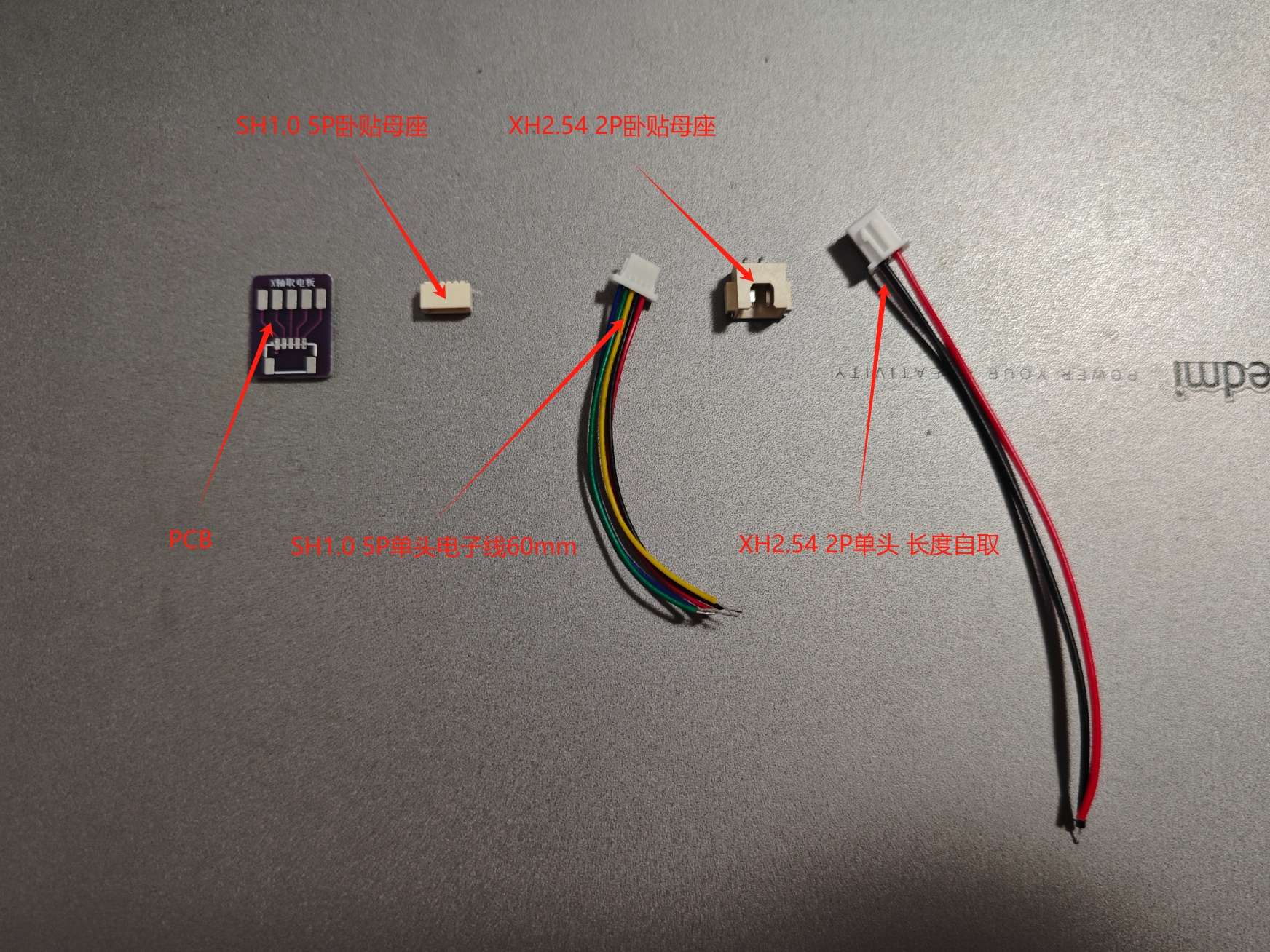
Topzhu A1M_X-axis power supply board
Suitable for Tuozhu A1MINI, it uses an adapter to connect a camera cable and extract a 5V power supply, which can be used to power an external camera or connect an external light strip.
First, you will need to prepare the following components: in addition to the PCB for this project, you will also need an SH1.0 5P horizontal mount female connector, a single-ended 60mm electronic cable, and an XH2.54 2P horizontal mount female connector. The cable length should be chosen according to your actual needs.
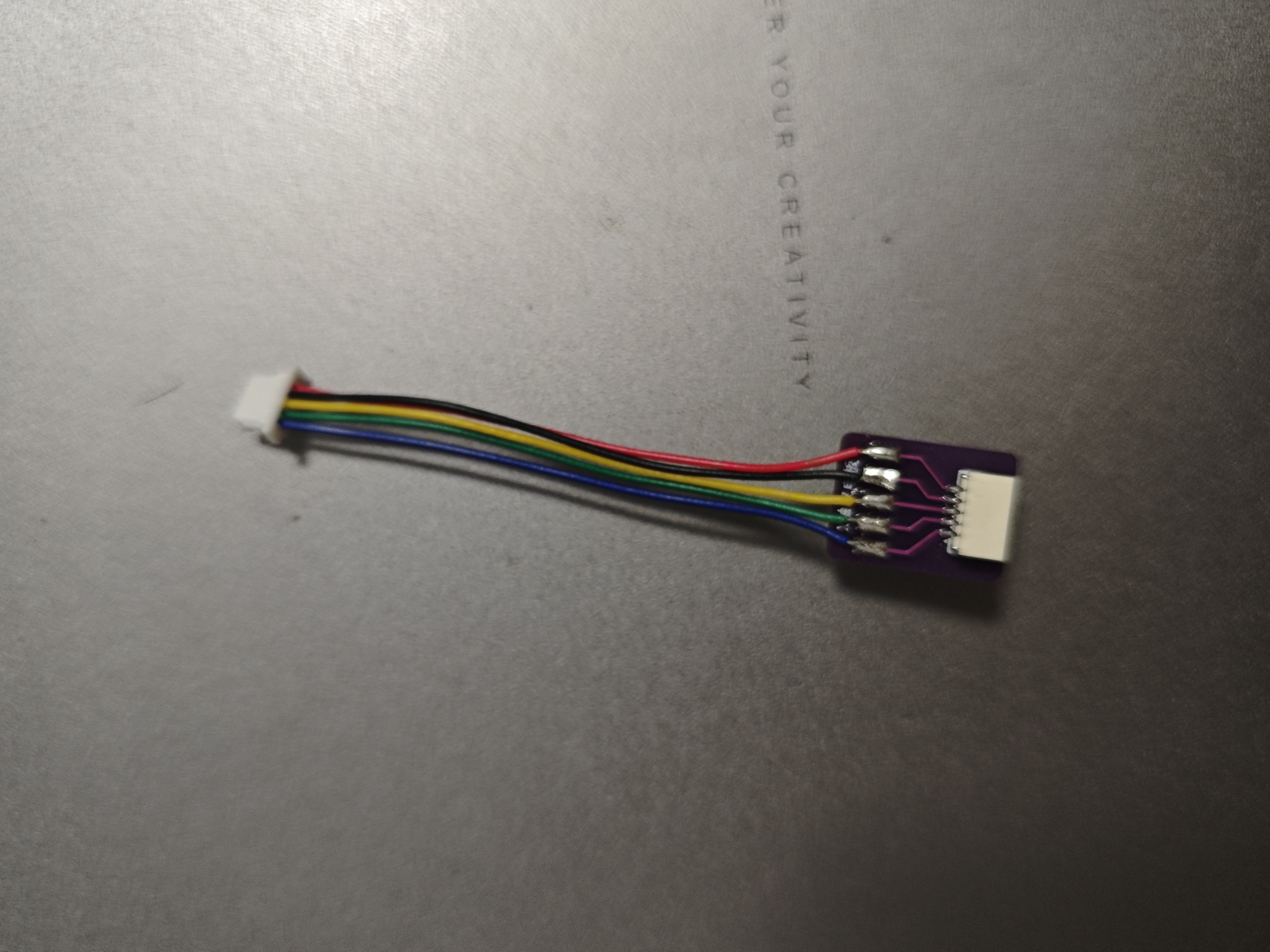
After soldering, it should look like the image below.

After soldering, you can install the printer.

Install the printer cover. The printer

with the cover closed.
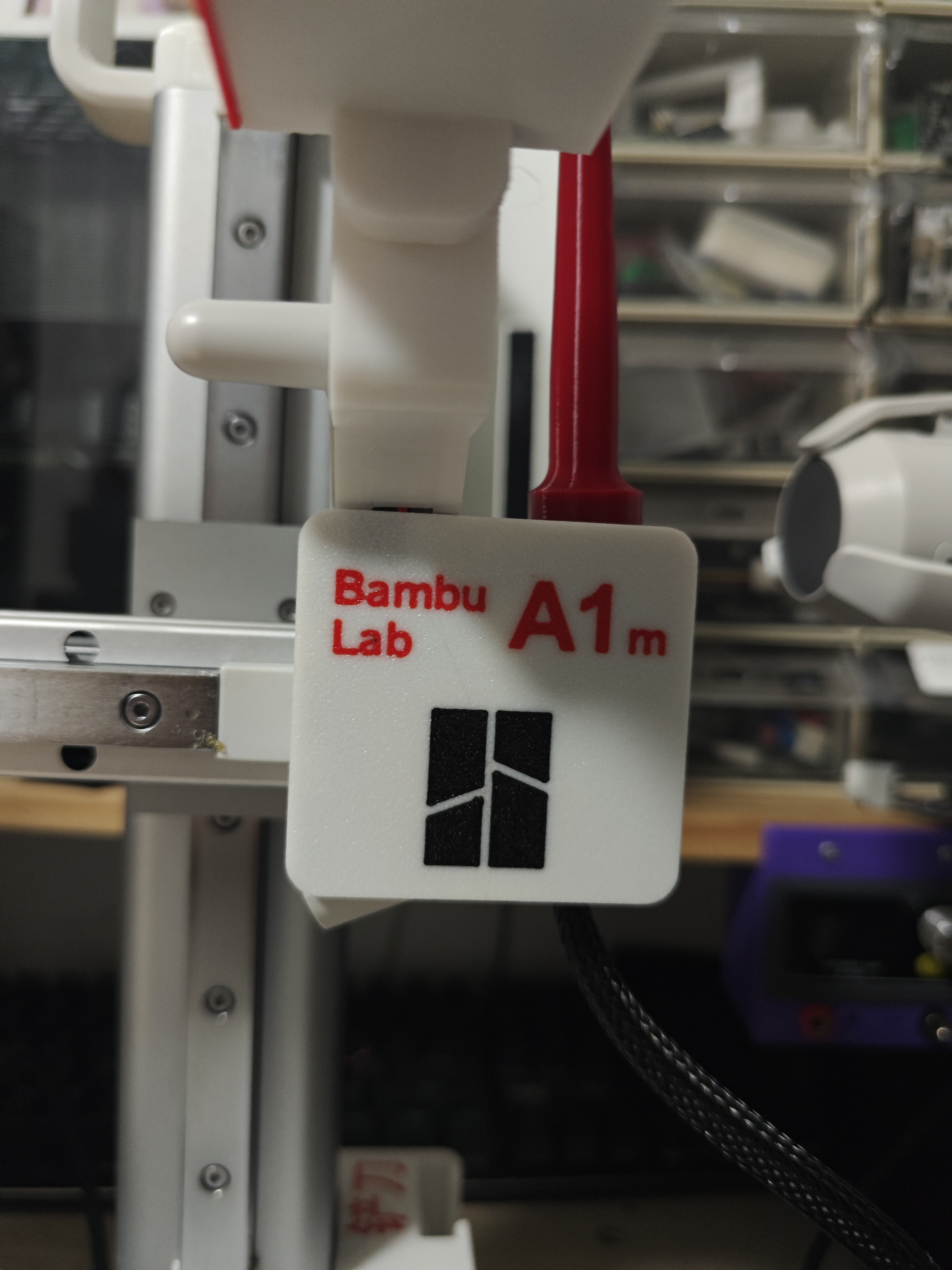
Done.
Advantages: It does not affect the original use of the printer's camera and lighting. A 5V power supply can be used to connect the camera or LED strip, eliminating the need for external power cables.
PDF_Tuozhu A1M_X-axis Power Take-off Board.zip
Altium_拓竹A1M_X-axis power supply board.zip
PADS_Tuzhu A1M_X-axis power supply board.zip
BOM_Tuzhu A1M_X-axis power supply board.xlsx
93245
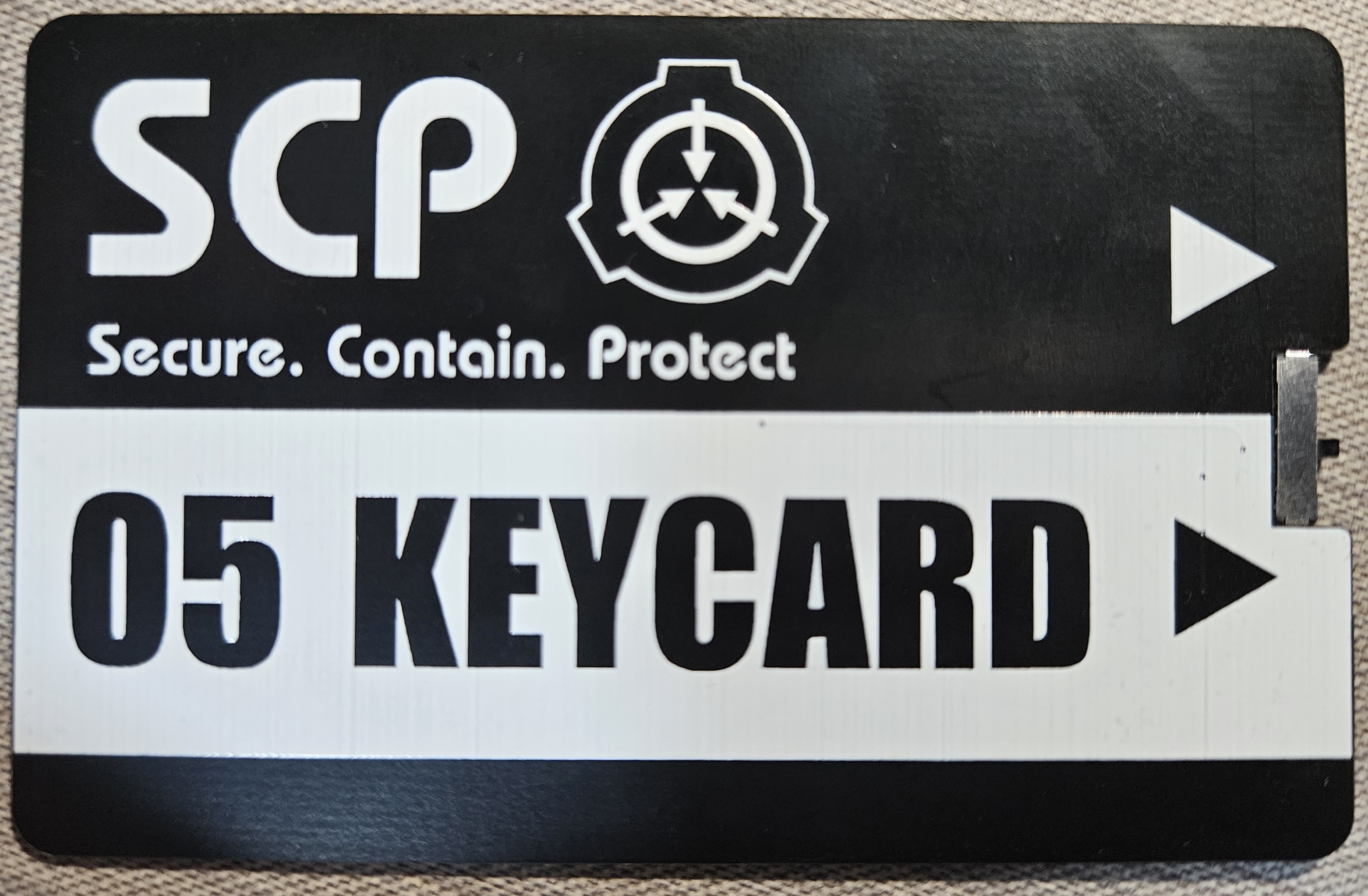
SCP 4-in-1 NFC Card
This 4-in-1 NFC card can be used as an access card or NFC tag.
(Modified from https://oshwhub.com/mazhiliang/nfc_card_4in1)
Item #: O5_NFC_Card
Item Class: EXPLAINED
Special Containment Procedures: At first glance, O5_NFC_Card does not pose an immediate danger. Use of O5_NFC_Card must comply with the CC BY-SA 3.0 license.
Description:
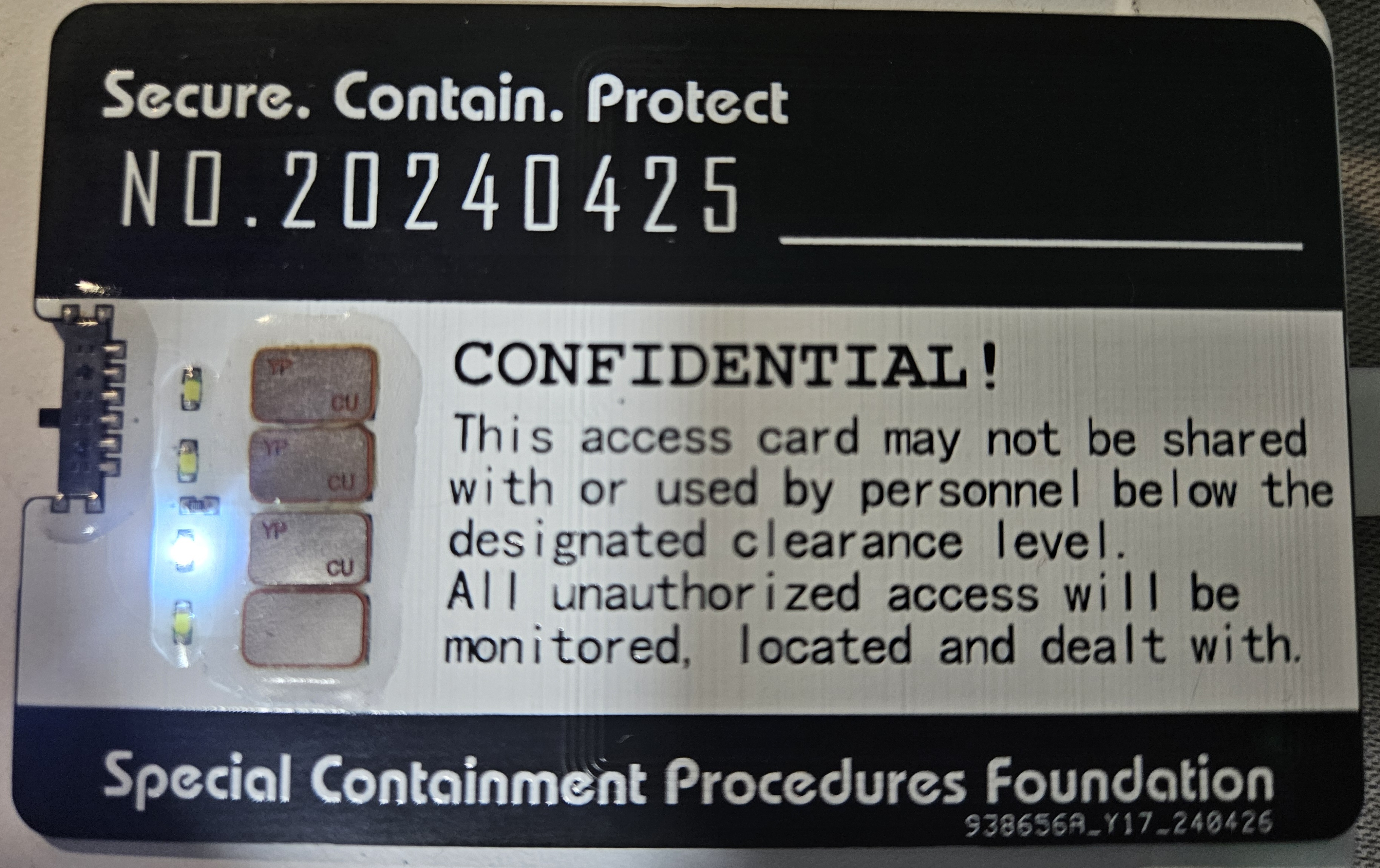
O5_NFC_Card is a standard card-sized printed circuit board measuring 85.6mm in length, 53.98mm in width, and 1mm in substrate thickness. Its dimensions are the same as a public transport card, and its appearance is similar to █████.
It contains an internal coil antenna with good sensitivity to electromagnetic waves at a frequency of 13.56MHz.
Ten solder pads are provided on the surface.
Experiment Record:
Date: ████████
Object: O5_NFC_Card
Experimenter: ███
Description: Apply low-temperature solder paste with a nominal melting point of 138°C to the pads.
Attach 4 NFC chips, 4 white 0603 package LEDs, 1 0603 package 100Ω resistor, and 1 4-position toggle switch to the corresponding locations.
Set a hot air gun to 250°C and heat the printed circuit board until the solder paste is completely melted.
Results: The O5_NFC_Card was tested using a mobile phone NFC sensor; the sensitivity was good.
The 4-position toggle switch was used to switch the connection between the antenna and different NFC chips; it functioned normally.
Appendix: The BOM is automatically generated and cannot be ordered directly.
The PCB thickness is 1mm (other thicknesses will cause the PCB edge to misalign with the toggle switch).
Only white LEDs were tested; other colors were not tested.
Polarity of LEDs and NFC chips does not need to be distinguished.
The 4-position toggle switch needs to be mounted upside down.
The reference shop is Dongguan Yuetai Electronics MSKT-14C01 on Taobao.
The NFC chip is 5*8mm in size and needs to be cut and trimmed with scissors. A reference shop is Taobao's Dexin IoT access
card store. It can use either UID or CUID chips (please refer to the relevant documentation for the differences).
The 216 chip is an NFC tag chip and is incompatible with the former (to be verified).
UV glue can be used to protect the components; be careful not to miss it.
The ID number on the back of the toggle switch can be modified; "JLCJLCJLCJLC" has been added to the file. Remember to select the specified customer editing position or modify the font file yourself. Other references can be found
at https://oshwhub.com/mazhiliang/nfc_card_4in1 . The appearance design references cv780337; thanks to Tangjia. Remember to add three spoons. The circuit part references nfc_card_4in1; thanks to mazhiliang.
SCP font.zip
PDF_SCP 4-in-1 NFC Card.zip
Altium_SCP 4-in-1 NFC Card.zip
PADS_SCP 4-in-1 NFC Card.zip
BOM_SCP 4-in-1 NFC Card.xlsx
93246
Automatic time synchronization stamp
This is a low-cost small stamp based on the STC8H microcontroller that can automatically synchronize time via Bluetooth. It was originally designed for special application scenarios where signatures and times are frequently required.
Project Introduction:
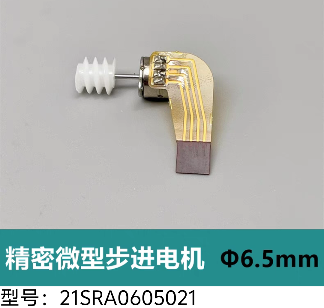
This is a palm-sized mechanical Bluetooth stamp that fits easily in a pocket. When needed, simply press a button and wait a few seconds for automatic time synchronization. It costs only around 50 yuan. It connects to Bluetooth for time synchronization, and when the button is pressed, it activates a stepper motor to drive the corresponding gears to the designated position, thus printing the hour and minute of the current time. Normally, it enters a low-power sleep mode.
Hardware
Solution: The main controller uses an STC8H microcontroller (programming requires a USB-to-TTL programmer). To save space, the circuit board does not include a programming chip or Bluetooth module, so the Bluetooth module needs to be connected externally via USB.
The clock chip used is the DS1302, a classic clock chip that needs no further explanation.
Instructions: Upon
initial power-up, you can connect via Bluetooth and control the time and calibrate the gear positions through a mobile app. Pressing the button sends 10 bytes of data via serial port. Excluding the header byte 0XA5, the second-to-last checksum, and the tail byte 0X5A, the data in the middle represents the hours, minutes, seconds, and the current position of the four gears. You can also calibrate it by sending corrected hour, minute, and second data, along with the required number of pulses for each of the four motors, in the same data format. See the attached code for the specific
software code . Note: The power can be restored via USB; a green light will illuminate when fully charged. Circuit board components can be purchased online. I used a stepper motor model 21SRA0605021, but you can use other models; simply modify the casing according to your needs. Project casing models are attached. [ Image of the actual product]

1000016174.jpg
mmexport1719128291823.mp4
1.stl
2.stl
3.stl
4.stl
5.stl
6.stl
7.stl
IMG_20240610_134714.jpg
IMG_20240704_165702.jpg
Assembly video.mp4
Mechanical seal.c
Mechanical stamp.hex
PDF_Automatic Time-Aligning Stamp.zip
Altium_Auto Time Stamp.zip
PADS_Automatic Time Stamp.zip
BOM_Automatic Time Synchronization Stamp.xlsx
93247
Cool encoder controller
This is a wireless speed-adjustable Bluetooth remote control. A hardware encoder rotates to modify the speed value, and a Bluetooth module sends the speed value to the slave device. To be precise, this isn't a ready-to-use open-source product; it needs to be used with the device being controlled, such as a remote-controlled car. The slave device is also compatible and can control temperature.
Application Scenarios for the Stepless Speed Regulator Bluetooth Controller Solution:
This project is specifically developed for the association's electric scooters. Therefore, in my application scenario, it aims to better control the scooters, achieving speed adjustment and zeroing via encoder. Future versions could potentially control home appliances, such as air conditioner temperatures. However, my current capabilities are limited, so I can only offer a Bluetooth-compatible control solution. Those interested can use the HC05 slave device to adjust light brightness, as it transmits numerical information via serial port. There are 10 speed levels, each transmitted via the HC05 Bluetooth module.
Usage
Instructions (Bilibili Video): [Bluetooth Speed Regulator? - Bilibili]
Press the motor power button to perform a power-on self-test and Bluetooth detection. After the HC-05 self-test is complete, it enters the control system. Left-hand encoder rotation accelerates the scooter while simultaneously transmitting the updated value via Bluetooth. Right-hand rotation does the same. Pressing the center button resets the speed to 0 and simultaneously sends the current speed data to the HC-05 slave device.
The BOM and component descriptions
for this project include several special components, such as encoders, two types of FPC cables, and solderable switches, which are niche components and feel quite expensive. For FPCs, this project uses two types of cables: one connects the encoder's digital display to the PCB of the digital display driver (JLCIC has a sample shop on Taobao where you can get a sample for one yuan); the other type connects the driver board to the main controller (this can be purchased directly on Taobao). Additionally, you will need to prepare M2*16 screws and nuts. Detailed parameters for purchasing from Taobao will be placed in the BOM folder. Make sure to choose the 28mm encoder. The total project cost is approximately 100+ RMB. The
attached images demonstrate
the assembly effect:
[Image of the assembly].

The attachment includes source code, BOM, and 3D printed parts.
Print parts.zip
YMills_Handel_controller_V3.0 official version.zip
Ymills_handle_controller_V3.0.eprj
BOM.zip
Image Effects.zip
PDF_Cool Encoder Controller.zip
Altium_Cool Encoder Controller.zip
PADS_Cool Encoder Controller.zip
BOM_Cool Encoder Controller.xlsx
93248
60-row split keyboard, KMK dual-mode solution
60-row split keyboard, KMK dual-mode solution
The development board I chose is NRFMicro (from an unknown tech seller on Taobao, it's cheap).
KMK is based on Circuit Python firmware. Download the corresponding Nice Nano firmware from the official website, install it into the bootloader, and once the development board recognizes it as storage, install the corresponding left and right-hand code.
60ss_left.zip
60ss_right.zip
PDF_60-inch Inline Split Keyboard, KMK Dual-Mode Solution.zip
Altium_60 Inline Split Keyboard, kmk Dual-Mode Solution.zip
PADS_60 Inline Split Keyboard, KMK Dual-Mode Solution.zip
BOM_60 Inline Split Keyboard, KMK Dual-Mode Solution.xlsx
93249
CJMCU_FT232_20PinOutlet
Have you been struggling with the 200+ RMB BusBlaster when debugging certain MCUs? This adapter board converts the CJMCU FT232 BreakOut board into a BusBlaster 20-pin header for easier debugging.
This adapter board is designed to replace the Busblaster and eliminate the need for a bunch of external DuPont wires every time. There are many expansion boards on the market with similar functions and sizes, and they may be cheaper than CJMCU's.
CJMCU FT232 baseboard: https://github.com/m3y54m/cjmcu-ft232hq-programmer
(You can also search for CJMCU on Taobao).
Note: This is currently an initial version; the author has only performed rough measurements, and there may be further changes. Please measure the dimensions of your purchased PCB and modify this project accordingly.
PDF_CJMCU_FT232_20PinOutlet.zip
Altium_CJMCU_FT232_20PinOutlet.zip
PADS_CJMCU_FT232_20PinOutlet.zip
BOM_CJMCU_FT232_20PinOutlet.xlsx
93252
electronic


 京公网安备 11010802033920号

 BZV55C24BSB


