High-power buck-boost power supply based on EG1151
: Input: 7~80V;
Output: 1.4~100V (depending on output capacitor; the chip supports 150V), 0~32A (this is the maximum current my equipment can measure).
Video demonstration: https://www.bilibili.com/video/BV1aw4m1k7mq/
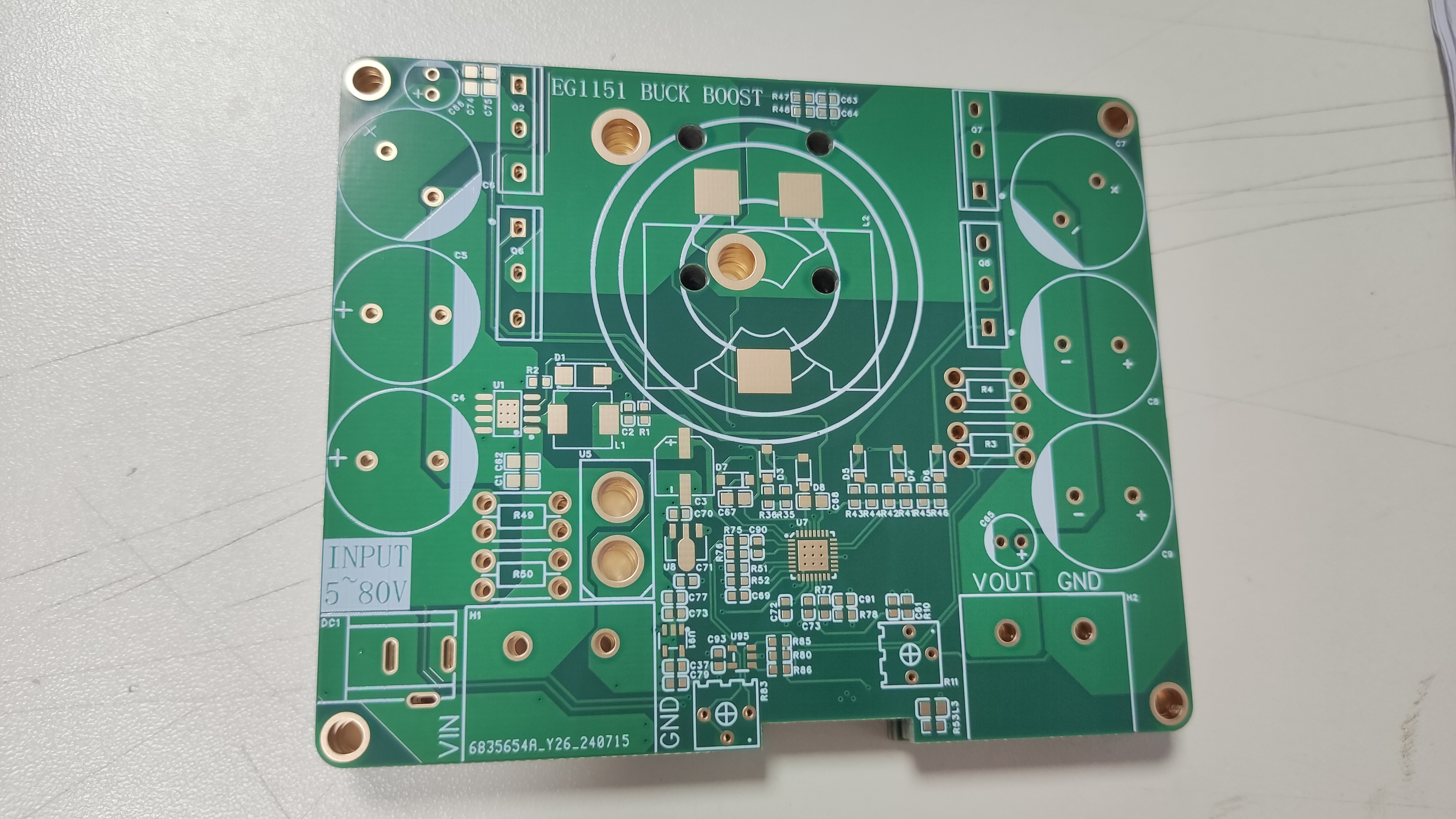
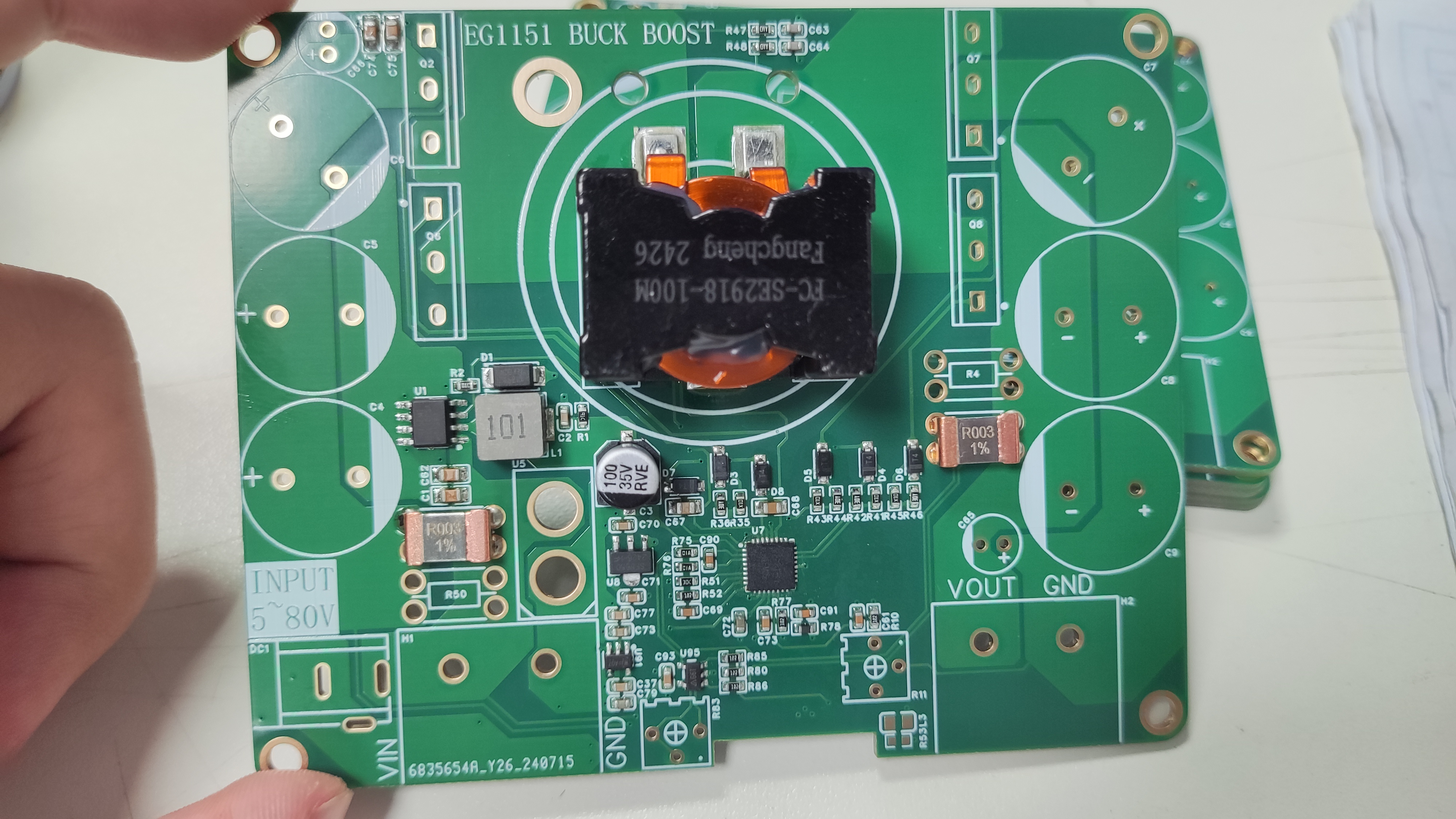
The MOSFETs should be bent 90 degrees from the back for easy heatsink placement. Insulating thermal pads are essential; short-circuiting the heatsink surfaces of the four MOSFETs is strictly prohibited.


PDF_EG1151 High Power Step-Up/Step-Down Power Supply.zip
Altium_EG1151 High Power Step-Up/Step-Down Power Supply.zip
PADS_EG1151 High Power Step-Up/Step-Down Power Supply.zip
BOM_EG1151 High Power Step-Up/Step-Down Power Supply.xlsx
93346
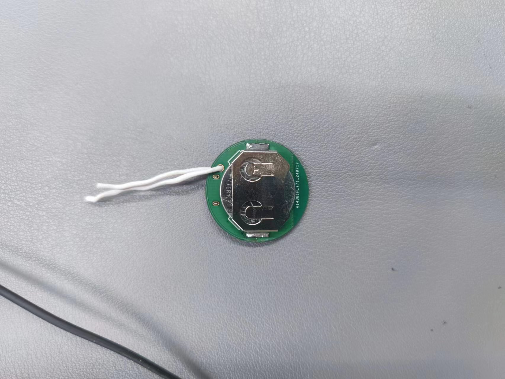
#9th LCSC Electronics Design Contest# Wireless Temperature and Humidity Detector - 414381A
This wireless temperature and humidity sensor combines high precision, miniaturization, portability, and low power consumption. It can be used as a small pendant or refrigerator magnet, and its temperature and humidity data are obtained from a mobile phone via Bluetooth.
* 1. Project Function Introduction:
A wireless temperature and humidity sensor that can detect the current ambient temperature and humidity data in real time and broadcast it via Bluetooth. Users can then search for nearby Bluetooth devices to view the data using their mobile phones. Supports Android and Apple phones, but not computers.
* 2. Project Attributes:
Version 1: Uses CH571R main controller, easy to solder, but with higher power consumption (60% higher than Version 2).
Version 2: Uses CH582F main controller, adds external DC-DC circuitry, reduces power consumption, and improves Bluetooth performance.
* 3. Open Source License:
This project is based on the GPL 3.0 open source license. Any product using the GPL license in a project must also use the GPL license, meaning it must be open source and free. The two most significant characteristics of the GPL are what is known online as "viral spread" and "disallowing closed-source commercial release."
* 4. Hardware
: Main Microcontroller: CH571R/CH582F
; Sensor: SHT40;
PCB Prototype: 1.2mm thick
* 5. Software:
The project is as follows, mainly consisting of two parts.

* Mount River Studio: You can open the attached project and modify it yourself.
*WCHISPTOOL software: Used for firmware flashing. The firmware is located in the obj directory.
*6. The BOM (Bill of
Materials) list is completely correct; you can follow the list.
*7. Competition logo verification.


*8. Demo your project and record a video for uploading.
BLE-TEMP-SHT40-CH582F.zip
Demo video.mp4
PDF_#9th LCSC Electronics Design Contest# Wireless Temperature and Humidity Detector - 414381A.zip
Altium_#9th LCSC Electronics Design Contest# Wireless Temperature and Humidity Detector - 414381A.zip
PADS_#9th LCSC Electronics Design Contest# Wireless Temperature and Humidity Detector - 414381A.zip
BOM_#9th LCSC Electronics Design Contest# Wireless Temperature and Humidity Detector - 414381A.xlsx
93348
STC32G12K128 Development Board
It adopts an STC32 microcontroller with all function pins brought out. It uses a TEPY-C interface for easy power supply and program download. It also has separate interfaces for the ESP826601S module and the NRF24L01-2.4G module. It uses a CH340N for easy debugging and program download.
For the main control chip, this design uses the STC32G12K128 microcontroller, which features high performance and rich peripheral interfaces. To maximize functionality, this development board exposes almost all of the STC32G12K128's full-function pins to meet diverse application needs.
Specifically, the design incorporates the ESP826601S module, which primarily utilizes pins P1.1 and P4.0. When using the ESP826601S module, to ensure its proper operation, pins P1.1 and P4.0 must be kept idle to avoid conflicts with other functions.
Furthermore, this development board integrates the NRF24L01-2.4G wireless communication module, which occupies pins P7.2 to P7.7. When using the NRF24L01-2.4G module for wireless communication, these pins must also be kept idle to ensure communication stability and reliability.
To facilitate debugging during development, this development board also features an OLED display interface, providing developers with an intuitive debugging tool that helps quickly detect and verify system status. This
is my first development board design, and there are many shortcomings; I welcome any corrections or suggestions from experienced developers.
Test video.mp4
PDF_STC32G12K128 development board.zip
Altium_STC32G12K128 development board.zip
PADS_STC32G12K128 development board.zip
BOM_STC32G12K128 development board.xlsx
93349
3255 Digital Power Amplifier
TPA3255DDVR Dual-Channel 300W Stereo Digital Amplifier, verified
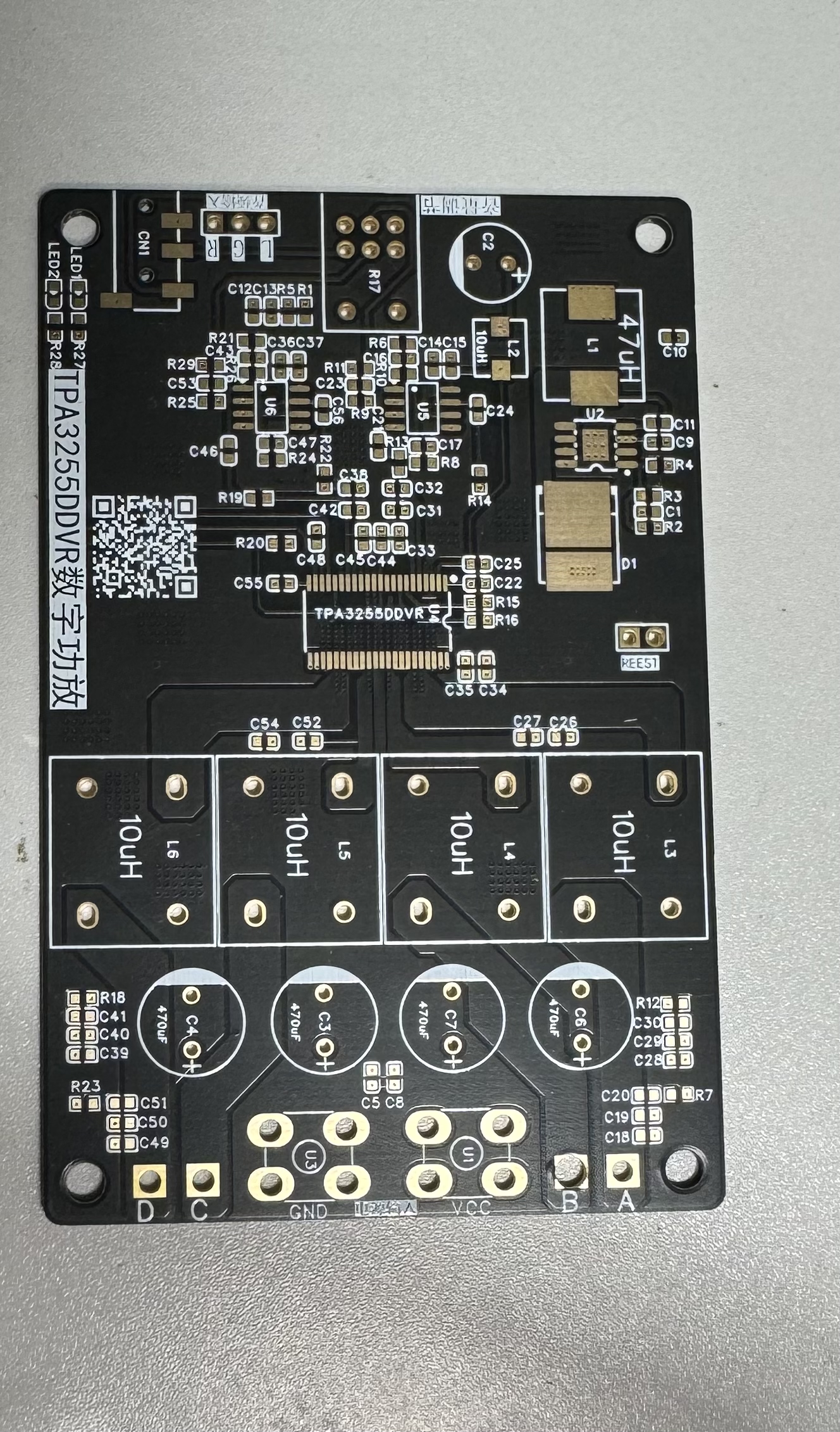
The TPA3255DDVR digital amplifier is a dual-channel 300W stereo digital amplifier with adjustable gain and low distortion. This is the most stable version after three improvements. A heatsink is recommended for the chip to achieve optimal performance.
The inductors used are KEDA CPD1715F high-current inductors, known for their excellent sound quality. Using other lower-quality inductors may result in issues such as inductor "singing" (overheating) and excessive heat generation; KEDA inductors are the preferred choice.
The op-amp has a gain of 6x; the gain can be adjusted by modifying the values of resistors R9 and R25.
Use high-power resistors for the output RC filter to prevent resistor burnout.
PDF_3255 Digital Amplifier.zip
Altium_3255 Digital Amplifier.zip
PADS_3255 Digital Amplifier.zip
BOM_3255 Digital Amplifier.xlsx
93350
STM32 stepless dimming lamp
A cute, low-power LED with continuously adjustable brightness and precise time display.
The STM32F103C8T6 main controller
detects button press status, communicates with the DS3231 via I2C to obtain time information, and generates two PWM channels to control LED brightness. When not in use, it enters a stop mode.
Of the six buttons, four control two LEDs with different color temperatures (brightness +, brightness -), one displays the time, and the other acts as a master switch for
the digital tube display .
Because driving the digital tube is quite power-intensive, the time display is set to turn on for 2 seconds when needed (when a button is pressed), and then turn off.
The LGS63032 boost LED constant current driver has
LED color temperatures of 4000K and 6000K, and a forward current of 60mA.
The maximum LED current is adjusted via an external sampling resistor; for details, please refer to the LGS63032 datasheet.
The
DS3231 is an I2C real-time clock (RTC) with a built-in temperature-compensated crystal oscillator (TCXO). When the module's power is interrupted, the device is powered by a CR2032 battery and maintains accurate time. The long-term accuracy of this device is improved by including a crystal oscillator. The DS3231 can track seconds, minutes, hours, days, dates, months, and years. This example only reads minutes + hours.
## The side-mounted buttons are really hard to press, they hurt my hand, and there are too many buttons, making it look clunky... Can't they make it a little more sophisticated? Coincidentally, I recently discovered a driver chip called JL7010S, which has touch control, brightness memory, and dual-channel LED control functions. Having it can greatly simplify the peripheral circuit and bring a better user experience. Forget about the ubiquitous C8T6; everyone should go look at the dual-color temperature stepless dimming lamp - JLCPCB EDA open-source hardware platform (oshwhub.com)
finished product showcase
, and
you're not allowed to stay up all night anymore!
Little Light Code.rar
VID_20240630_014702.mp4
This file includes button debouncing.rar
PDF_stm32 stepless dimmer lamp.zip
Altium_stm32 stepless dimmer lamp.zip
PADS_stm32 stepless dimmer lamp.zip
BOM_stm32 Stepless Dimmable Lamp.xlsx
93352
Taishanpai PD charging & discharging + fuel meter solution verification
Supports internal PD charging and external discharging. Application scenario: A single USB-C port can charge and connect to USB devices while discharging them.
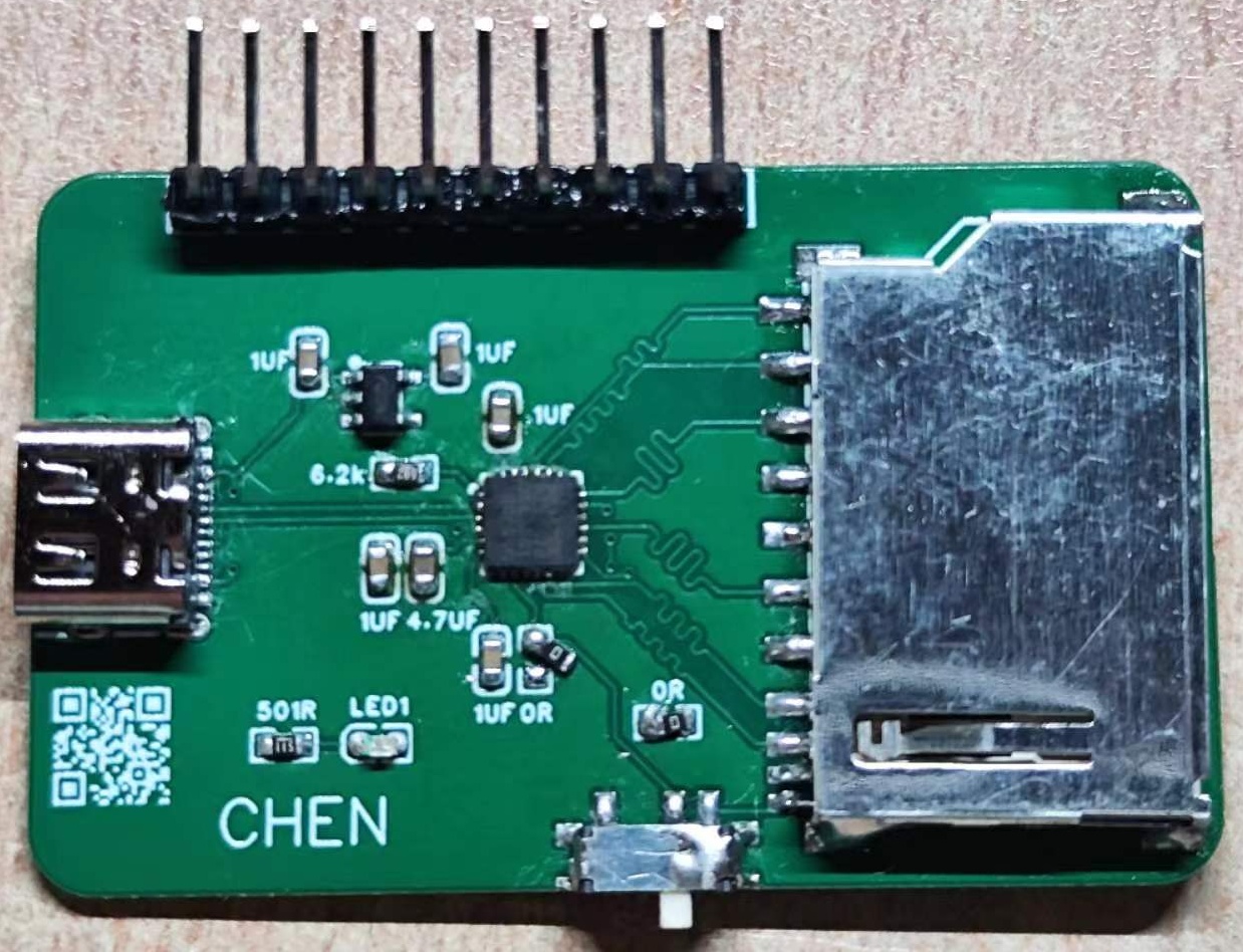
PD Fast Charging + Fuel Meter Verification Board
1. Introduction:
Supports the PD fast charging protocol, allowing customization of PD protocol voltage and current parameters. It supports custom modification of charging current, cutoff voltage, and other parameters.
It also supports automatic switching between charging and discharging; plugging in a PD charger initiates charging, while plugging in a USB device or other electrical appliance discharges at 5V (a USB flash drive is a typical example).
This allows a single Type-C port to both charge the battery via PD and discharge via a USB device. Linux systems can then recognize the USB device.
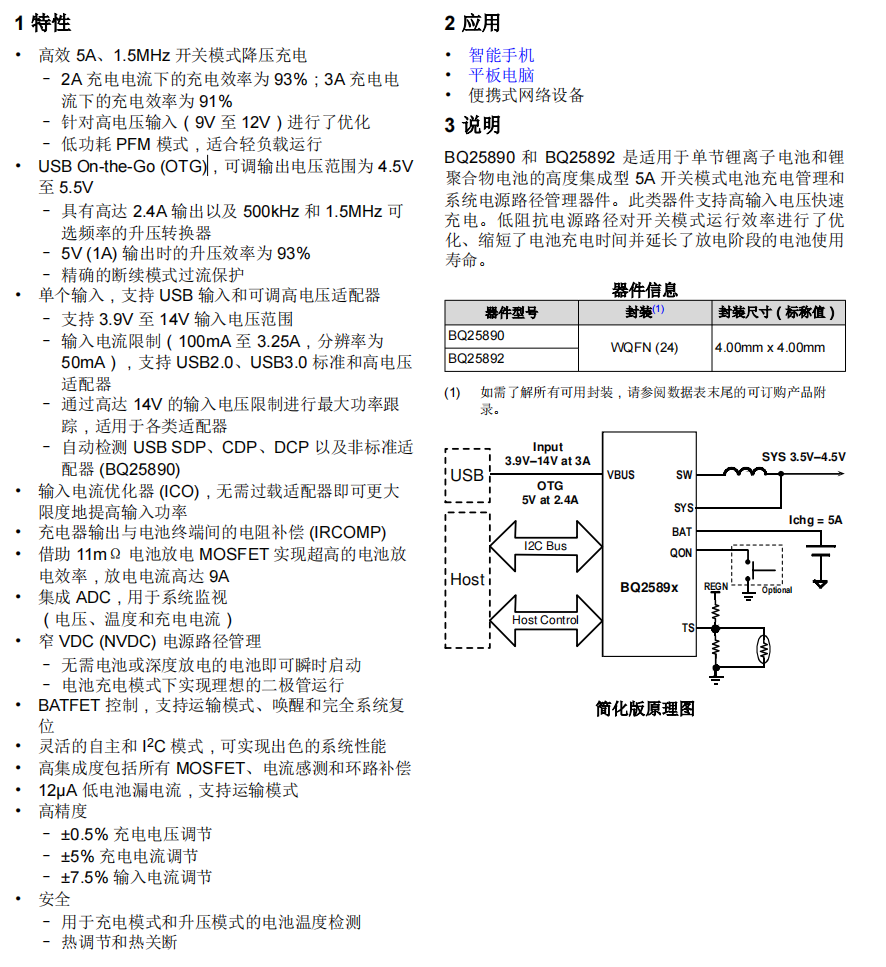
1.1 BQ25890
Charging IC: The BQ25890 features MaxCharge™ technology, enabling a high input voltage and adjustable voltage USB On-the-Go
boost mode I2C controlled single-cell 5A fast charger. In discharge mode, it delivers a maximum output of 5.5V + 2.4A, with adjustable device parameters.
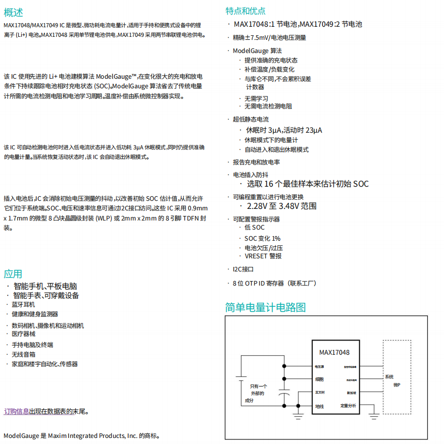
1.2 MAX17048G+T10
The MAX17048 is a miniature, low-power current/fuel meter suitable for lithium-ion (Li+) batteries in handheld and portable devices. Its
I2C communication interface is extremely simple and requires no voltage divider resistors.
1.3 FUSB302BMPX
The Fusb302 is a programmable USB Type-C controller that supports the identification of various USB devices and their corresponding statuses; it also supports PD protocol up to 100W.
The Fusb302 communicates with the Type-C power adapter using the CC1/CC2 pins, setting the power adapter's output voltage and current via the PD protocol to control the charging voltage and current, thus achieving fast charging.

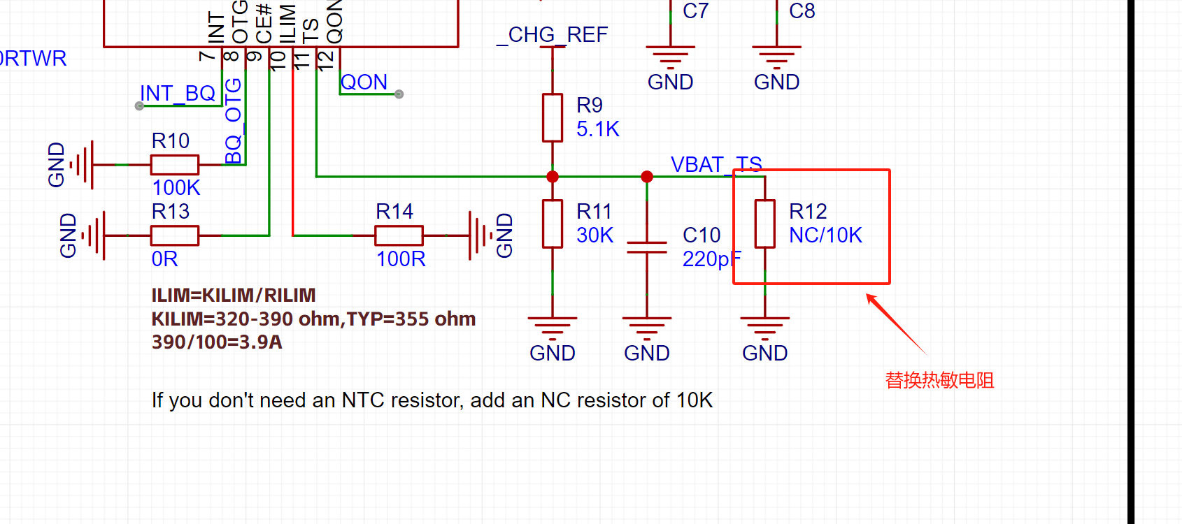
2. Verification Module Scheme Diagram

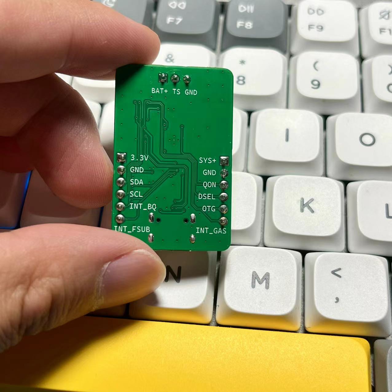

As shown in the diagram above, an external battery needs to be connected to a 10K thermistor for temperature protection. Ignoring this will result in the charging indicator light flashing rapidly, indicating an error.
If you don't want to connect a 10K thermistor, you can add the following resistor:
3. Test 12V PD request + charging power
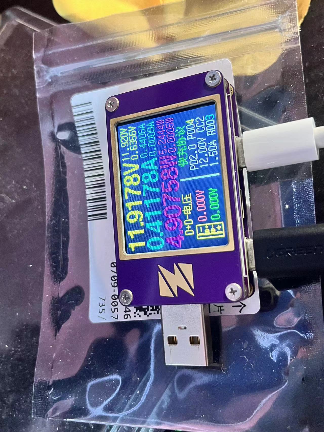
4. Taishanpai successfully ported fuel meter driver printout information
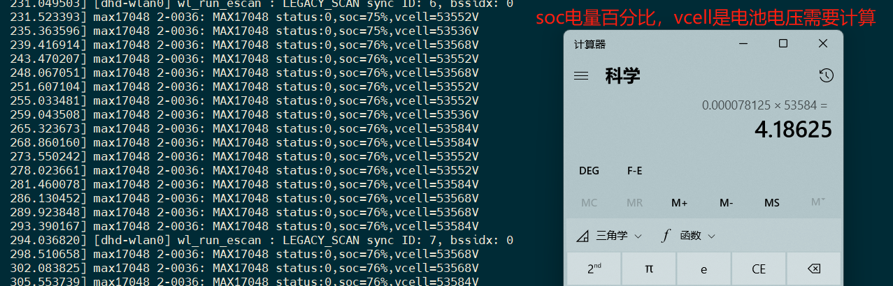
Use the Linux battery management subsystem to register the driver, you can view the voltage and SOC percentage in /sys/class/power_supply/battery/
5. Driver porting
This time we used Taishanpai I2C2 interface, the IO usage is shown in the figure below

5.1 Modify device tree
Modify the file: tspi-rk3566-user-v10-linux.dts
Add the following code segment
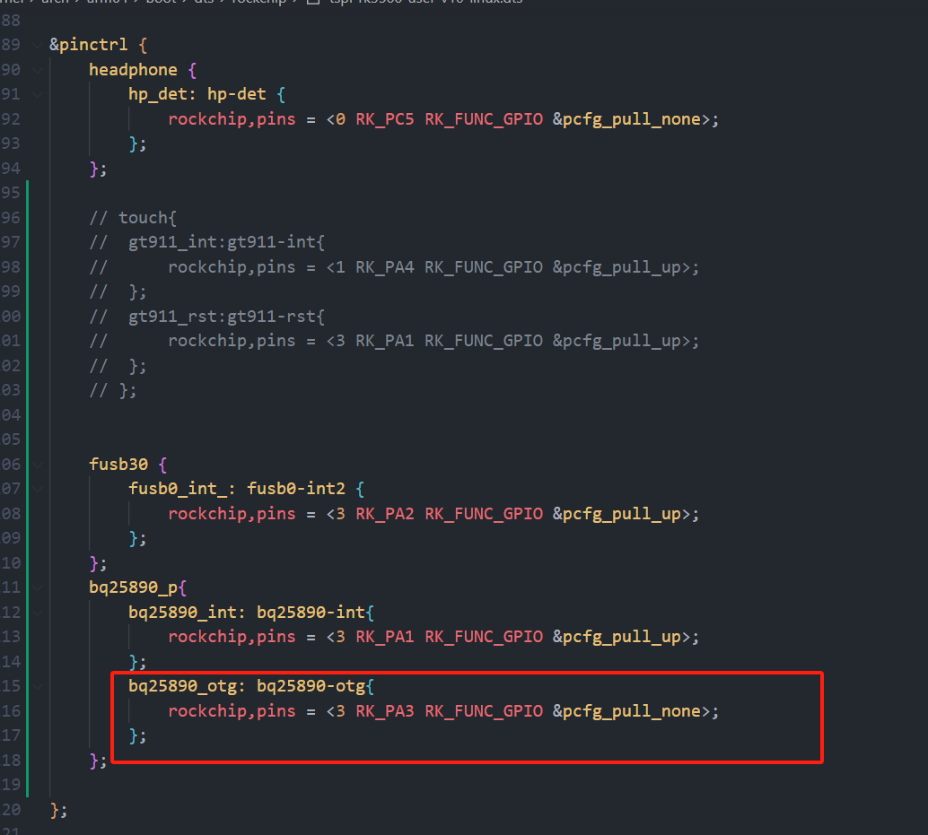
&pinctrl {
........
fusb30 {
fusb0_int_: fusb0-int2 {
rockchip,pins = <3 RK_PA2 RK_FUNC_GPIO &pcfg_pull_up>;
};
};
bq25890_p{
bq25890_int: bq25890-int{
rockchip,pins = <3 RK_PA1 RK_FUNC_GPIO &pcfg_pull_up>;
};
};
//END
};
Add I2C node
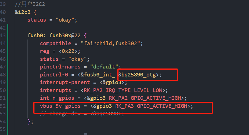
//User I2C2
&i2c2 {
status = "okay";
..................
fusb0: fusb30x@22 {
compatible = "fairchild,fusb302";
reg = ";
status = "okay";
pinctrl-names = "default";
pinctrl-0 = <&fusb0_int_>;
interrupt-parent = <&gpio3>;
interrupts = ;
int-n-gpios = <&gpio3 RK_PA2 GPIO_ACTIVE_HIGH>;
// charge-dev = <&bq25890>;
};
bq25890:bq25890@6a{
status = "okay";
compatible = "ti,bq25890";
reg = �;
// extcon = <&fusb0>;
interrupt-parent = <&gpio3>;
interrupts = ;
pinctrl-names = "default";
pinctrl-0 = <&bq25890_int>;
ti,battery-regulation-voltage = <4200000>;
ti,charge-current = <2000000>;
ti,termination-current = <50000>;
ti,precharge-current = <128000>;
ti,minimum-sys-voltage = <3700000>;
ti,boost-voltage = <5000000>;
ti,boost-max-current = <3000000>;
ti,use-ilim-pin;
ti,thermal-regulation-threshold = <120>;
};
max17048:max17048@36{
status = "okay";
compatible = "max17048";
reg = 6;
};
};
Configure the kernel to enable driver support for bq25890.
In the kernel directory, execute the command: `make ARCH=arm64 menuconfig`. Enter/open the search bar for `bq25890` and enable "[*]" to compile into the kernel.
Execute: `make ARCH=arm64 saveddefconfig`
to overwrite the configuration: `mv defconfig arch/arm64/configs/rockchip_linux_defconfig`.
Copy the battery meter driver file (see attachment at the bottom) to the specified directory:
`kernel/drivers/power/supply/max17048_battery.c`
. Modify the file: `kernel/drivers/power/supply/Makefile`. Add the following to the last line:
`obj-y += max17048_battery.o`.
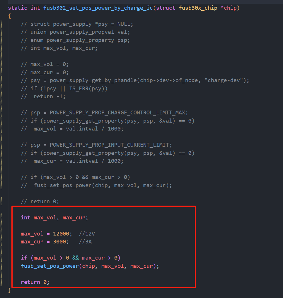
Modify the driver file: `kernel/drivers/mfd/fusb302.c`.
Modify the method name: `static int fusb302_set_pos_power_by_charge_ic(struct fusb30x_chip *chip)
int max_vol, max_cur;
max_vol = 12000; //12V
max_cur =` 3000; //3A
if (max_vol > 0 && max_cur > 0)
fusb_set_pos_power(chip, max_vol, max_cur);
return 0;
Add print information:
printk("fusb302---->%s:get vol = %d
", __func__,CAP_FPDO_VOLTAGE(chip->rec_load[tmp]) * 50);
printk("fusb302---->%s:get cur = %d
", __func__,CAP_FPDO_CURRENT(chip->rec_load[tmp]) * 10);

Compile the kernel: ./build.sh kernel
burn the boot image.
Start the development board and set the log printing level: dmesg -n 7
to view the fuel gauge print data.
2. Version Change Log
2.1 20240803: Modified driver to adapt to automatic charging + automatic external discharge capability.
The automatic external discharge function in the original bq25890 driver code is to obtain
the source code of the USB-PHY node listening ID event. It is written as follows:
/* OTG reporting */
//USB_PHY_TYPE_USB2 USB 2.0 PHY. This enumeration defines the USB PHY type used in the Linux kernel, describing the type of the PHY to which the USB controller is connected.
`bq->usb_phy = devm_usb_get_phy(dev, USB_PHY_TYPE_USB2);
` If `bq->usb_phy` is notified, then
`dev_info(dev, "USB controller found");
INIT_WORK(&bq->usb_work, bq25890_usb_work);
bq->usb_nb.notifier_call = bq25890_usb_notifier;
usb_register_notifier(bq->usb_phy, &bq->usb_nb);
` Otherwise, `
dev_info(dev, "USB controller not found %ld
",(unsigned long)bq->usb_phy);
`
A brief explanation of the original code:
The `Type` is obtained from the kernel as `USB_PHY_TYPE_USB2`. The USB 2.0 usbPhy driver.
If usbPhy is found, it registers a listener event, which listens for the USB pin ID being pulled low. Here's the problem: our Type-C interface is not MicroUSB and doesn't have an ID pin. Also, `bq->usb_phy` always returns "usbPhy device not found". I added log printing to the internal code loop and found that the loop wasn't even being entered, indicating that usbPhy internally hadn't registered any RK USB devices. I don't understand the specific reason why RK's internal USB driver uses some other method. I won't investigate it here because listening for the ID low event is impractical.
The source code implements automatic charging as follows:

So how is the external output voltage implemented? I summarized it directly from the documentation: two points:
OTG pin high level && OTG_CFG register 1.If the condition is not met, it indicates charging mode.
Solution: By default, set OTG_CFG to 1, and then control the high and low states of the OTG pins to control charging and discharging.
However, a question arises: how do we know whether a charger or an electrical appliance (e.g., a USB flash drive) is plugged in?
Solution:
Utilize the internal implementation of the FUSB302 driver. Looking at a section of code within the FUSB302 driver,
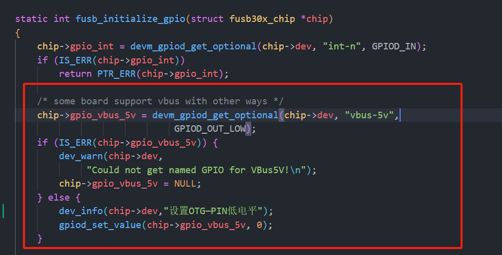
it turns out that the fusb302 has already anticipated this requirement, so it's already designed in.
We simply need to modify the bq25890 driver to set OTG_CFG to 1 by default, and then let FUSB control the OTG pins itself.
After figuring it out, it turns out it's so simple, wow~ so easy!
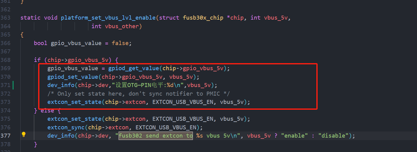
Here's the code modification part:
Modify the bq25890 path: kernel/drivers/power/supply/bq25890_charger.c.
Add the following code to the last line of the static int bq25890_probe(struct i2c_client client,const struct i2c_device_id id): dev_info(bq->dev,"USB enabled OTG Boost mode");
bq25890_field_write(bq, F_OTG_CFG, 1);
as shown in the image below

. Modify the device tree and add code in two places:
I tested C2C USB devices and it worked fine. Then I had a VFD screen with CC1 and CC2 connected to ground via 5.1K. I found that directly connecting to C2C could not trigger discharge, but if I added a C-to-A interface and plugged in the cable (A2C), it could discharge my device.
Then I also connected a solid-state enclosure to C2C and it discharged normally.
Discharge prompt upon insertion:
[3297.073050] fusb302 2-0022: Set OTG-PIN level: 1
[3297.073953] fusb302 2-0022: CC connected in CC1 as DFP
max17048_battery.c
PDF_Taishanpai PD Charging & Discharging + Fuel Meter Solution Verification.zip
Altium_Taishanpai PD Charging & Discharging + Fuel Meter Solution Verification.zip
PADS_Taishanpai PD Charging & Discharging + Fuel Meter Solution Verification.zip
BOM_Taishanpai PD Charging & Discharging + Fuel Meter Solution Verification.xlsx
93353
RTS5170 TF/SD-C Female Connector - Card Reader
The RTS5170 C-type female card reader is more convenient to use.
It can read and write the boot partition under Linux systems.
Based on: rts5170_card_reader - JLCPCB EDA open source hardware platform (oshwhub.com). Inspiration for the modification
came from eMMC programmers and MMCFW card reader tutorials - Creative DIY Digital Home (mydigit.cn).
The above is a sample. The new version adds two 0603 specification 5.1k resistors, solving the problem of the CC data cable not being recognized by the computer.

(Note: the component is a 2.54mm pitch 10pF male connector!!!)
It supports use with products from my other projects.
The modified version adds a dual voltage switching function (VCCQ line can switch between 1.8V and 3.3V), and offers self-ejecting/non-ejecting TF card slots
. A 65K5 component is used for voltage reduction, which may have optimized the issue of VCCQ 1.8V not working (to avoid potential problems caused by using the 3.3V line for voltage reduction, it was modified to use the VBUS line for voltage reduction).
However, in my actual testing, seven or eight Samsung eMMC chips were not recognized in the 1.8V state. I added this feature simply because I saw something a member of the programmer group said, and I wrote it down on a whim.
PDF_RTS5170-TF-SD-C Female Connector-Card Reader.zip
Altium_RTS5170-TF_SD-C female connector-card reader.zip
PADS_RTS5170-TF_SD-C Female Connector-Card Reader.zip
BOM_RTS5170-TF_SD-C Female Connector-C Card Reader.xlsx
93354
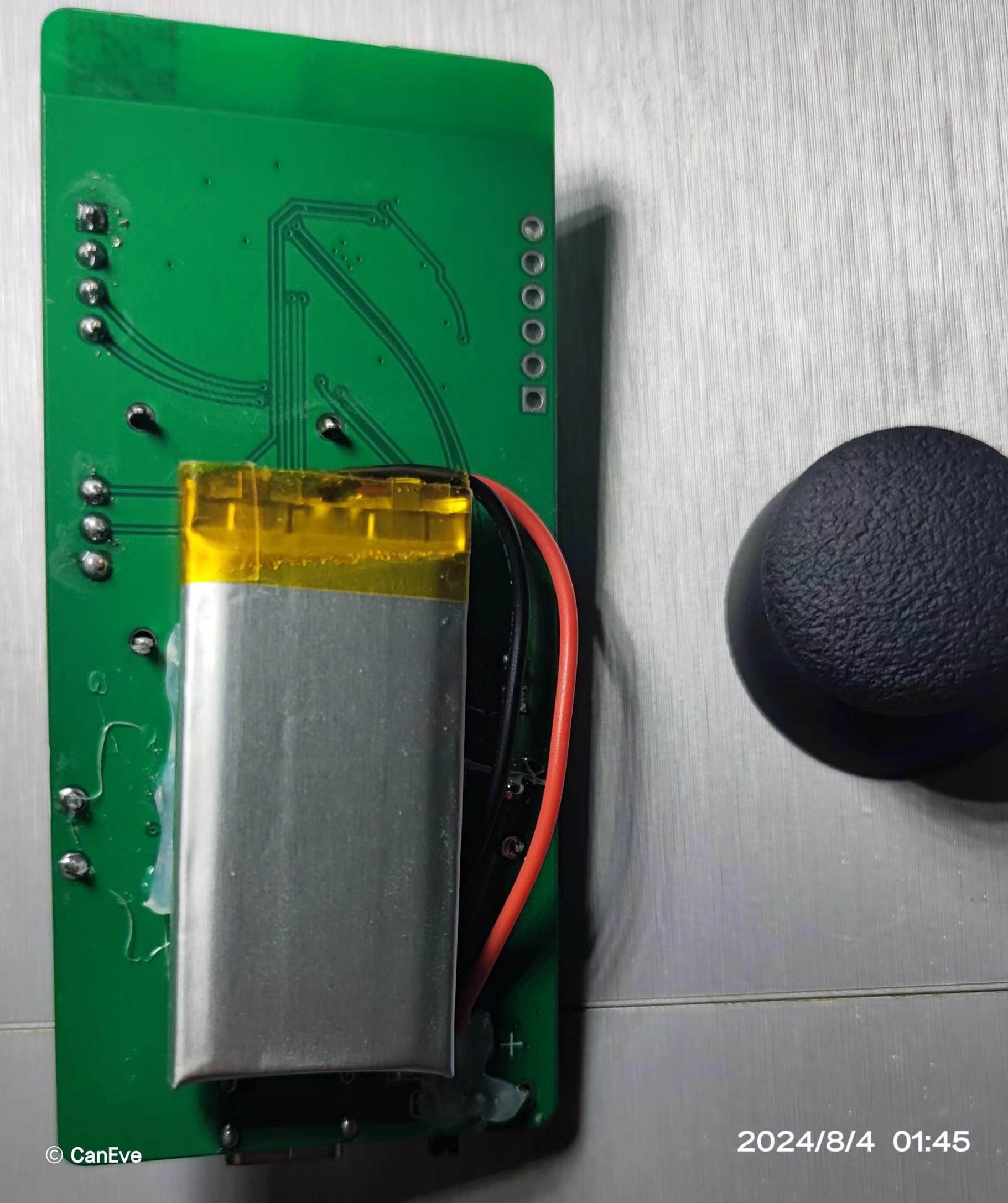
Linear joystick mouse
CH571F Bluetooth USB Joystick Mouse
Currently, only the Bluetooth part of the program is written. Wired connectivity has been tested, but it's not yet fully functional (
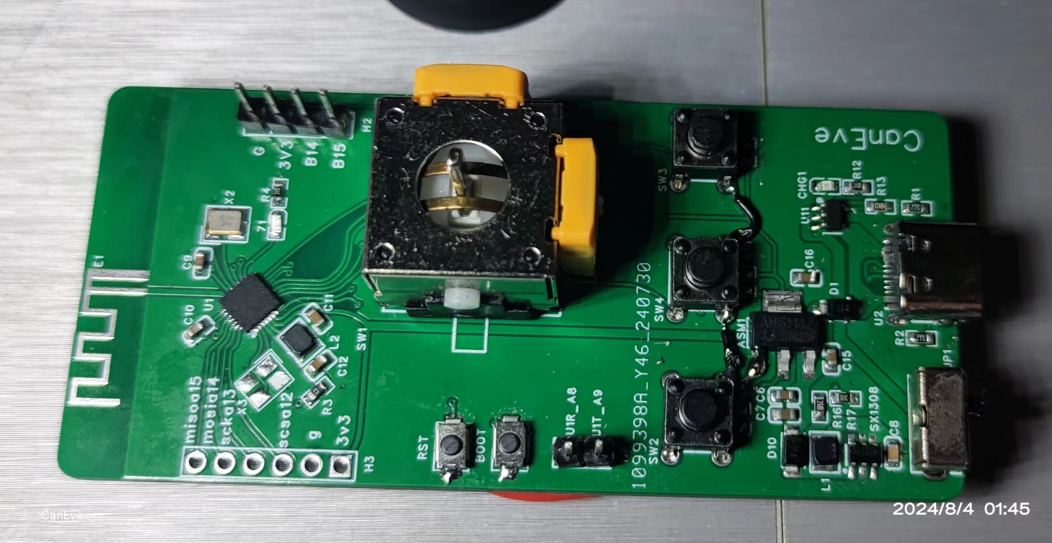
it can charge and be used while plugged in).
Demonstration video: https://www.bilibili.com/video/BV1L5v9edE6v/?share_source=copy_web&vd_source=459737722f5dfdf793fbf1bfbf777987
Software open-source link: https://gitee.com/caneve/opencaneve/tree/main/CHx
Component parameters can be found in the schematic diagram; do not refer to the BOM (Bill of Materials).
PDF_Linear Joystick Mouse.zip
Altium Linear Joystick Mouse.zip
PADS_Linear Joystick Mouse.zip
BOM_Linear Joystick Mouse.xlsx
93355
ESP32 development board with battery management
Battery management functionality has been added to the esp-wroom-32 development version.
Battery management functionality has been added to the esp-wroom-32 development version.
PDF_ESP32 Development Board with Battery Management.zip
Altium_ESP32 Development Board with Battery Management.zip
PADS_ESP32 Development Board with Battery Management.zip
BOM_ESP32 Development Board with Battery Management.xlsx
93356
electronic


 京公网安备 11010802033920号

 100-4P5-T1-B13-M7-R-E-HDW15


