* 1. Project Function Introduction:
The temperature and humidity measuring instrument project uses the STM32G030K6T6 chip as the main control chip, with an Arm Cortex-M0+ core, a maximum clock frequency of 64MHz, 32KB of Flash, 8K of SRAM, and a power supply voltage of 2.0V~3.6V.
It uses IIC communication to collect temperature and humidity data from the SHT40 sensor and displays the data through a digital tube.
During idle time, it enters a low-power sleep mode; pressing a button enters normal operation mode, and after operation, it automatically enters low-power sleep mode, waiting to be woken up by pressing a button.
It is powered by a lithium battery, with an onboard dual power supply automatic switching circuit: lithium battery (3.0-4.2V) and Type-C power supply (5V).
The Type-C interface is used to charge the lithium battery and power the operating circuit.
Function Demo: https://b23.tv/9zeGwvK
*2. Project Attributes
Revealed for the First Time
* 3. Open Source License:
GPL 3.0 ,
Third Edition, GNU General Public License, released by the Free Software Foundation (FSF).
If a product under the GPL license is used in an engineering project, then the project must also use the GPL license, which means: open source and free.
>
Open source license explanation link: LCSC Open Source Hardware Platform Announcement [Help Document] Open Source Hardware Platform Open Source License Explanation
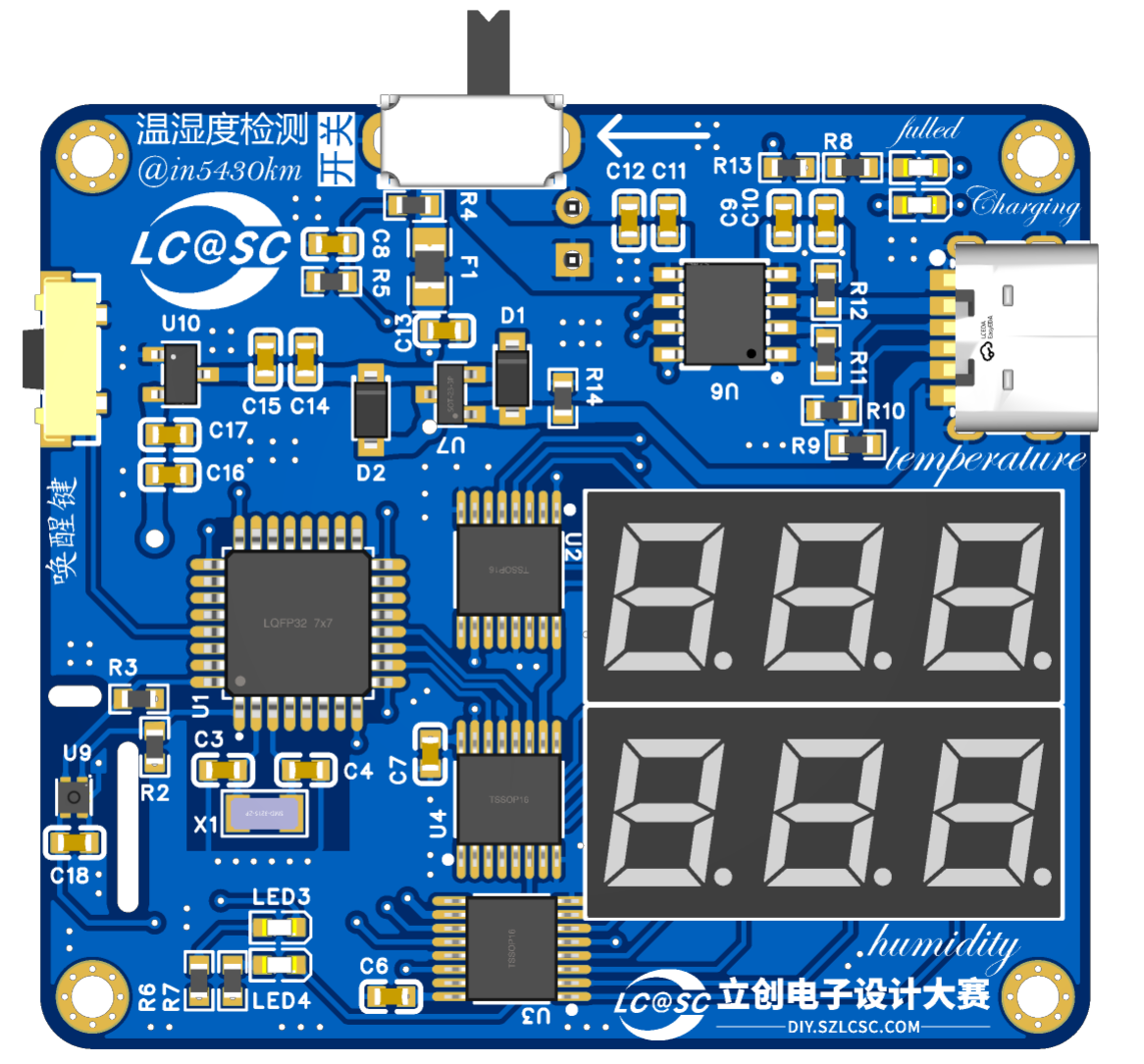
*4. Hardware Part
MCU Circuit
STM32G030K6T6, NRST default pull-up reset, external LSE clock source 32.768kHz

Figure 1 MCU Main Control Circuit Diagram

Figure 2 MCU Internal Structure Block Diagram
Temperature and Humidity Sensor Circuit + Power Monitoring Circuit + Operation Indicator Circuit
SHT40-AD1B Sensor Chip, I2C Communication Interface Default Pull-up; Main Circuit Series Equivalent Resistor Voltage Divider, Branch Circuit ADC Acquisition; Button Operation + LED Indicator
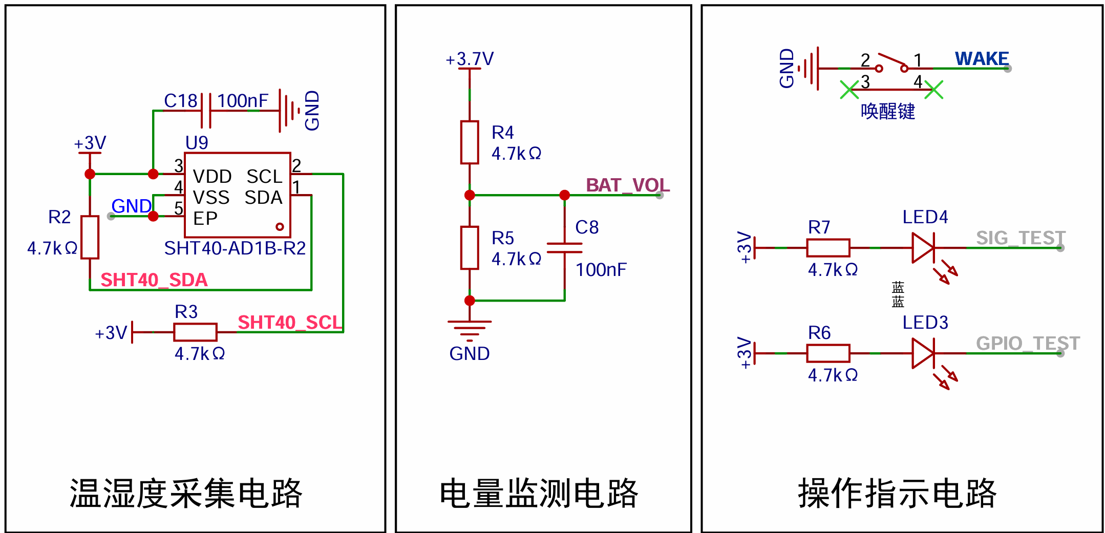
Figure 3 Temperature and Humidity Sensor Circuit, Power Monitoring Circuit, Operation Indicator Circuit Diagram

Figure 4 Pseudo Code Provided by SHT40 Sensor Manual

Figure 5 I2C Communication Code
I2C (Inter-Integrated Circuit): A commonly used synchronous serial communication protocol.
I2C devices are connected to the bus through open-collector or open-drain pins, pulling the line low.
When there is no data transmission, the I2C bus is in a high-level idle state due to the external pull-up resistors on the circuit.
When data transmission is needed, the level is first pulled low and then released (returning to the initial state: high level), and the data bits are transmitted on the falling edge generated by SDA under the SCL clock signal.
Hardware I2C does not require viewing the specific communication timing of the I2C device; it is handled by the hardware.
Simulated I2C requires attention to the communication timing of the I2C device, simulating its timing to achieve communication.

Figure 6 shows a schematic diagram of the I2C connection .
The digital tube driver circuit
consists of three 74HC595 chips to display two three-digit digital tubes.
One 74HC595 chip is used to control the common cathode port of the digital tube LED, and the other two 74HC595 chips are used to control the positive port of the digital tube.
When LEDx_n (x: 1-2, n: AH) outputs a high level and LEDx_DIGn (x: 1-2, n: 1-3) is controlled to a low level, the corresponding LED inside the digital tube is turned on, i.e., lit.
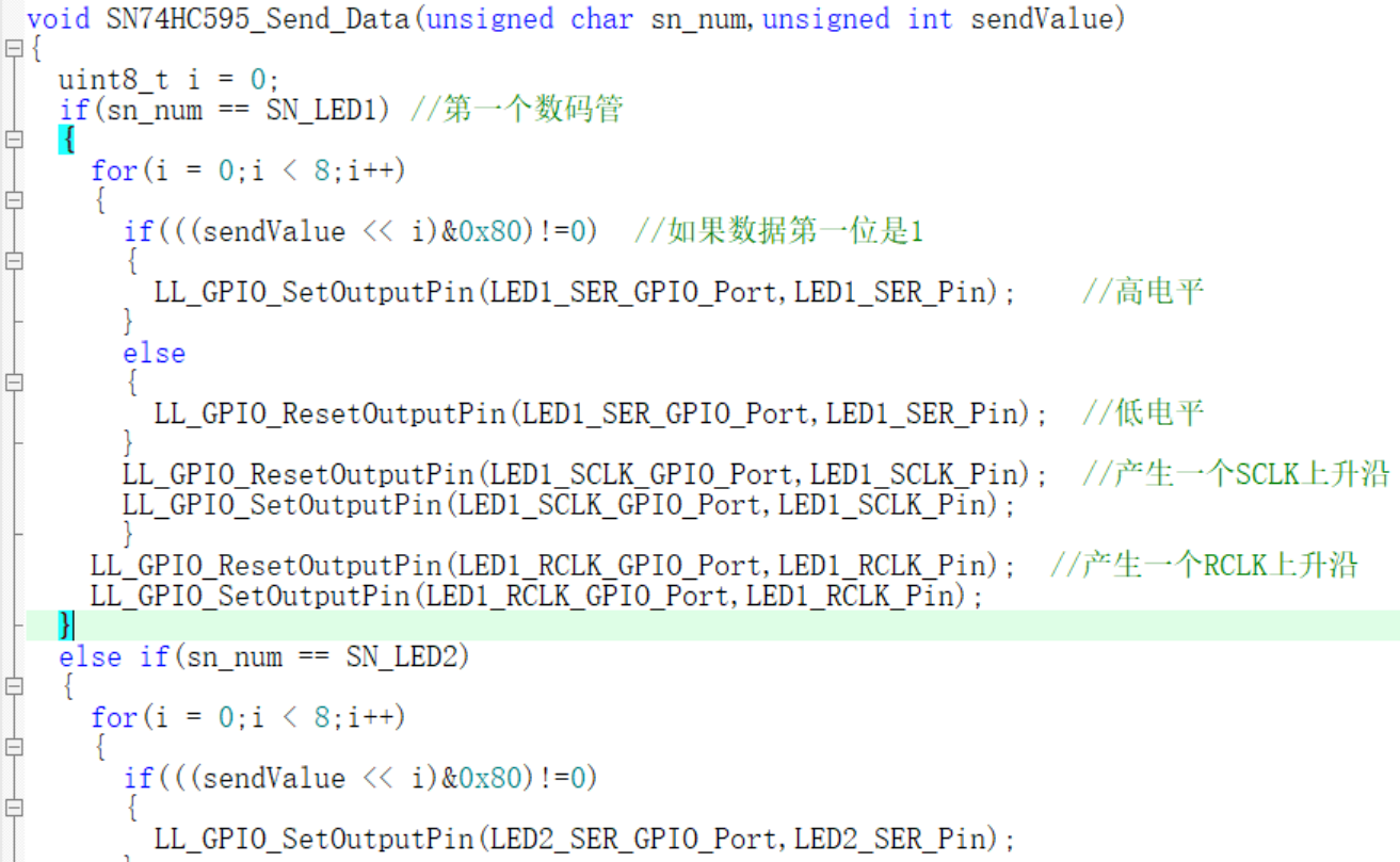
The 74HC595 chip consists of a shift register and an output register. The shift register receives serial input data and performs shift operations, while the output register latches the data in the shift register and provides parallel output. Data is serially input into the shift register via the SER pin. The SRCLK pin provides a clock signal; when the rising edge of the signal arrives, the data in the shift register is shifted. When data needs to be latched, a clock signal is provided using the RCLK pin. When the rising edge of the signal arrives, the data in the shift register is latched into the output register.
(Transmission occurs one bit at a time, with a total of one byte transmitted each time; 1 byte = 8 bits)

Figure 7: Digital tube driver circuit diagram. Lithium battery
charging
circuit: The lithium battery charging circuit uses the TC4056A chip. The charging current is controlled by adjusting the resistance value of R11. Formula: I = 1200/Rprog (current unit: mA; resistance unit: kΩ)
Charging state: CHRG is low level, STDBY is high level, i.e. (red light on, green light off).
Fully charged state: STDBY is low level, CHRG is high level, i.e. (green light on, red light off).

Figure 8 Lithium battery charging circuit
diagram 1 TC4056A status table
Charging state
Red light CHRG (7 pins)
Green light CHRGT (6 pins)
Charging On Off Battery fully charged Off
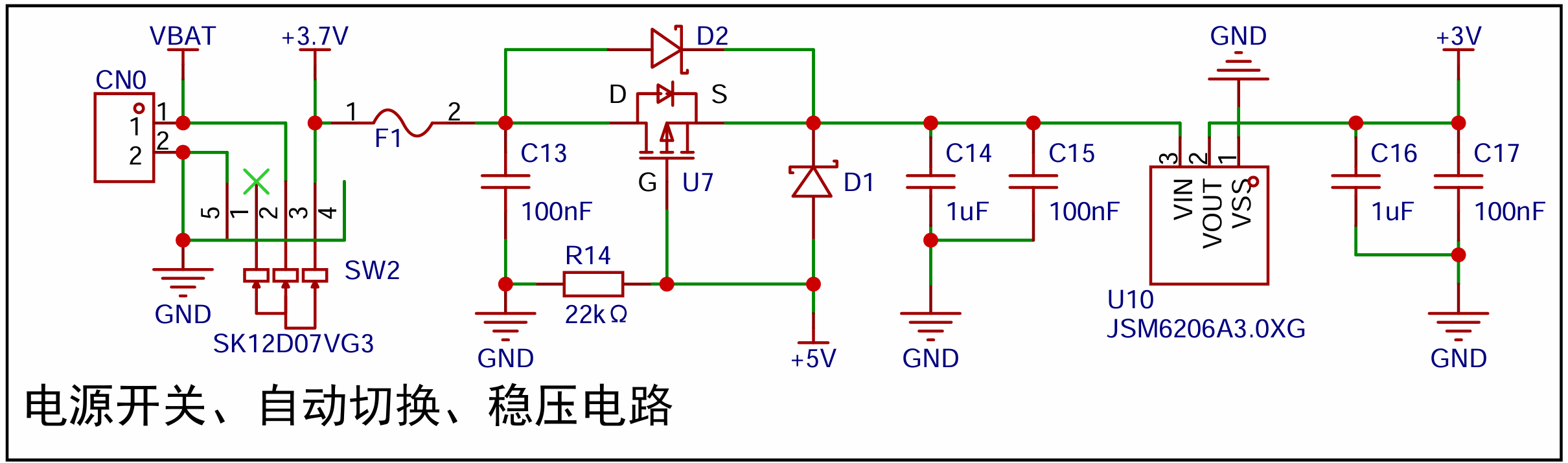
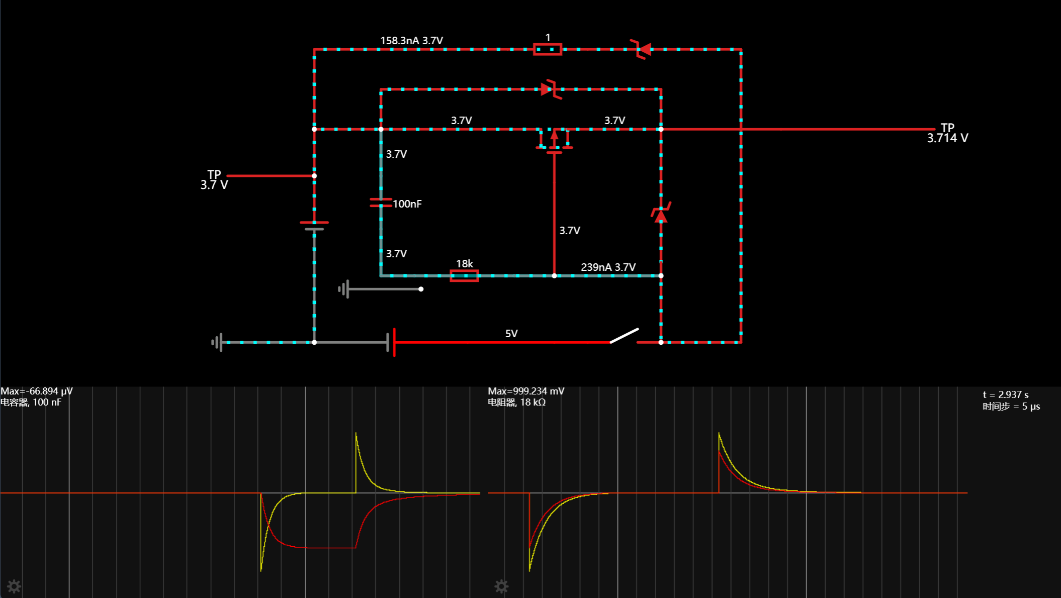
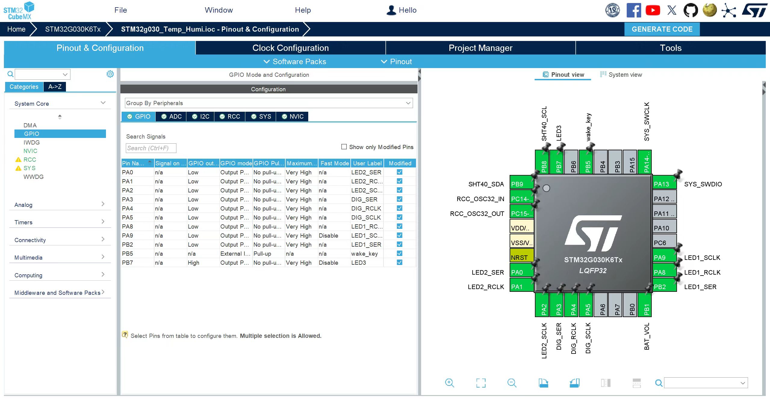
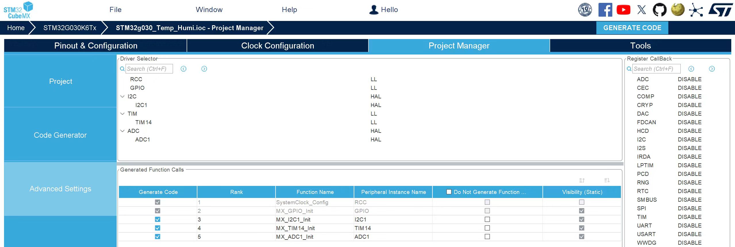
VCC = 5V Battery reversed Off VCC =5V No battery connected Off (*) After the battery is reversed , the LED display will remain completely off. It can only be restored to other states after the battery is connected correctly, or it can be restored after disconnecting the battery and waiting for 10 seconds. When the 5V port is floating, the gate of the PMOS transistor is pulled down to ground (0V) through resistor R14. The lithium battery BAT (3.7~4.2V) reaches the source through the internal body diode of the PMOS transistor, and the source voltage is (3~3.5)V. At this time, Ugs is (-3.5)V to (-3)V. When 5V is connected, Ugs reaches the source through diode D1, and the source voltage is 4.3V. The gate voltage is 5V, Ugs=5-4.3=0.7V>Uth. At this time, the MOS transistor is turned off, and the output Vout=4.3V(5-0.7). Diode D2 acts to increase discharge and reduce power switching time. Note: The voltage difference between the two power supplies must be greater than 0.7. This circuit is referenced from the external power supply and lithium battery automatic switching circuit diagram 9 shows the power supply circuit diagram. Online simulation of the circuit shows that the dual power supply switching time is approximately 10ms (100nF capacitor + 18kΩ resistor). In the circuit diagram above, if C13 = 220nF and R14 = 10kΩ, after simulation, the switching time is approximately 20ms, i.e., 50Hz. Figure 10 Automatic Power Switching Simulation Diagram *5, Software Part: STM32CubeMX Configuration Project Code
For detailed configuration, please refer to the attached IOC file.
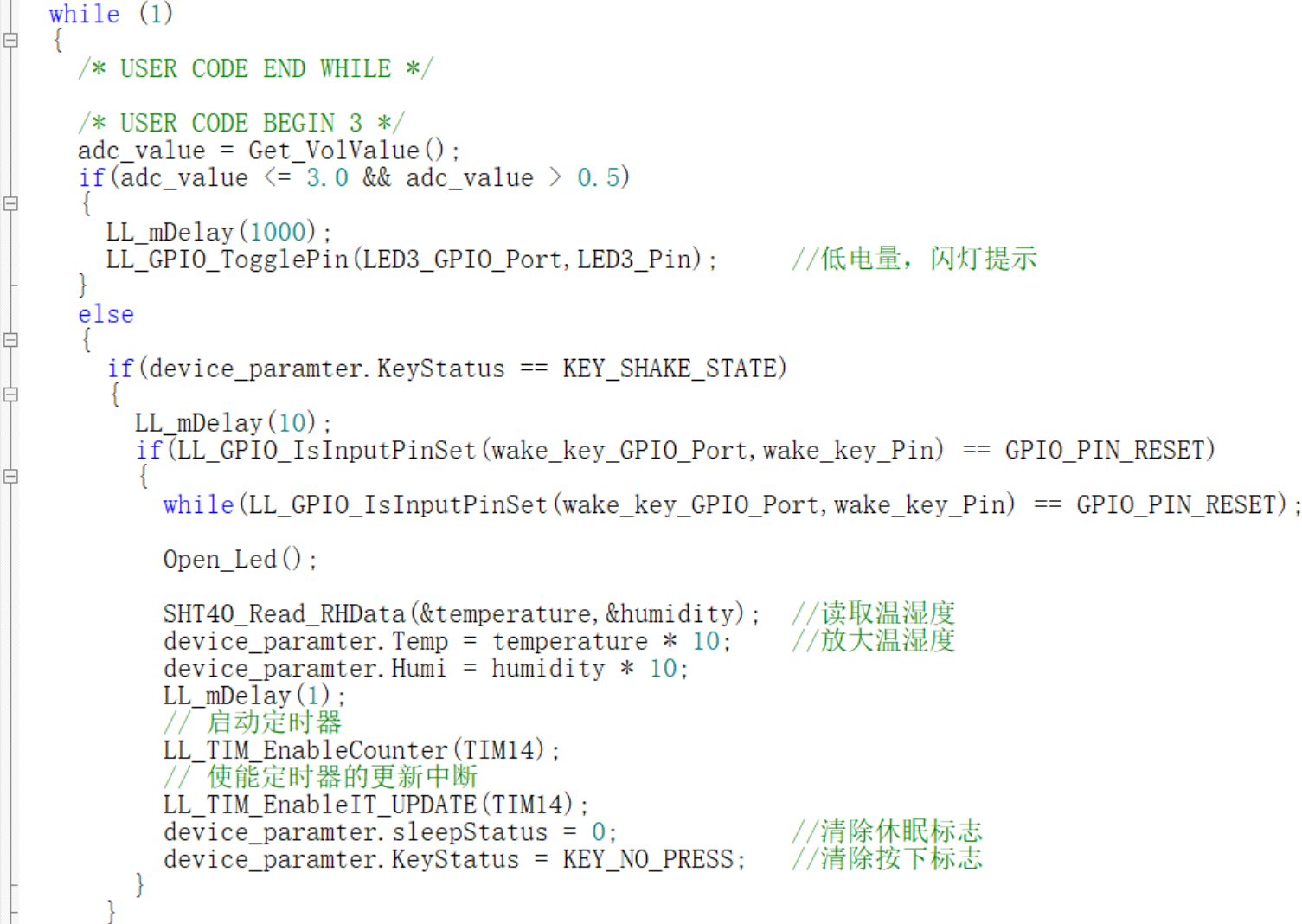
MDK programming project main
program >>

Partial digital tube driver code >>
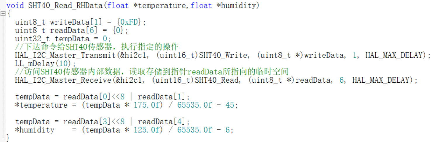
Obtain SHT40 sensor temperature and humidity data >>
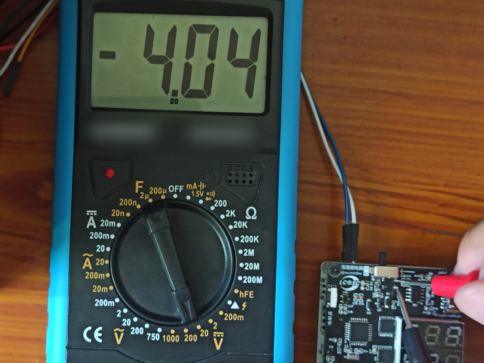
ADC voltage acquisition >>
volvalue = (adc_value*(3.03F-0.15F))*2/4095.0F.
In the ADC acquisition circuit seen earlier, two equal resistors in series divide the voltage of the lithium battery in this part, so the ADC acquires half of the total voltage. Here, *2 is used.
The actual measured MCU voltage VDD/VDDA is 3.01V. The subtracted 0.15 is considered an error (I previously tried using an HK chip for ADC voltage acquisition, achieving accuracy to three decimal places, but ADC testing on this current MCU revealed a significant error; the specific reason is unknown).
The STM32G030's ADC resolution is 12 bits, so 4095 = 2^12 - 1. This indicates that the internal voltage of 3V can be divided into 4095 parts, each representing 0.000732 volts (V). The formula in the code is essentially a proportional transformation.
Note: The voltage of the object being measured must not exceed VDD; otherwise, the measured power supply voltage will be inaccurate because it exceeds the measurement range!


*6. BOM List
Number
Quantity
Remarks
Tag Number
Package
Value
LCSC Item Number LCSC
Price
Manufacturer
Material Cost
1
9
100nF
C1,C2,C8,C10,C12,C13,C15,C17,C18
C0603
100nF
C14663
0.013981
YAGEO
0.125829
2
2
20pF
C3,C4
C0603
20pF
C105621
0.014605
YAGEO
0.02921
3
5
1uF
C5,C6,C7,C14,C16
C0603
1uF
C59302
0.030538
FH
0.15269
4
2
10uF
C9,C11
C0603
10uF
C77044
0.067488
muRata (村田)
0.134976
5
1
HC-XH-2AW-G
CN0
CONN-TH_2P-P2.50_HC-XH-2AW-G
C5341208
0.107373
HCTL (华灿天禄)
0.107373
6
2
MBR120LSF
D1,D2
SOD-123_L2.8-W1.8-LS3.7-RD
C130880
0.2192
SHIKUES (时科)
0.4384
7
1
BSMD0805-050-6V
F1
F0805
C883108
0.276183
BHFUSE (佰宏)
0.276183
8
1
CBG160808U000T
L1
L0603
C43163
0.024165
FH (Fenghua)
0.024165
9
2
SP420281N
LED1,LED2
LED-SEG-TH_SP420281N
C122944
2.1663
ARKLED (Fangzhou)
4.3326
10
2
XL-1608UBC-04
LED3,LED4
LED0603-RD_BLUE
C965807
0.02253
XINGLIGHT (Chengxingguang)
0.04506
11
1
SZYY0603R
LED5
LED0603-R-RD
C434419
0.041609
yongyu (Yongyu Optoelectronics)
0.041609
12
1
XL-1608PGC-06
LED6
LED0603-RD_GREEN
C7371905
0.0586
XINGLIGHT (成兴光)
0.0586
13
4
M2
P1,P2,P3,P4
M2
0
0
14
3
10kΩ
R1,R8,R13
R0603
10kΩ
C25804
0.005579
UNI-ROYAL (Thick Sound)
0.016737
15
6
4.7kΩ
R2,R3,R4,R5,R6,R7
R0603
4.7kΩ
C23162
0.006472
UNI-ROYAL (Thick Sound)
0.038832
16
2
5.1kΩ
R9,R10
R0603
5.1kΩ
C23186
0.006186
UNI-ROYAL (Thick Sound)
0.012372
17
1
2.4kΩ
R11
R0603
2.4kΩ
C22940
0.006003
UNI-ROYAL (Thick Sound)
0.006003
18
1
250mΩ
R12
R0603
250mΩ
C422951
0.022713
UNI-ROYAL (Thick Sound)
0.022713
19
1
22kΩ
R14
R0603
22kΩ
C31850
0.006147
UNI-ROYAL (Thick Sound)
0.006147
20
1
GT-TC054A-H035-L1
SW1
SW-SMD_L7.8-W3.5-P4.20-EH
C778158
0.24573
G-Switch (Pinzan)
0.24573
21
1
SK12D07VG3
SW2
SW-TH_SK12D07VG3
C431547
0.130586
SHOU HAN
0.130586
22
2
Test-Point
SWCLK,SWDIO
Test-Point-0.5mm
0
0
23
1
STM32G030K6T6
U1
LQFP-32_L7.0-W7.0-P0.80-LS9.0-BL
C529331
4.7
ST (STMicroelectronics)
4.7
24
3
SN74HC595PWR
U2,U3,U4
TSSOP-16_L5.0-W4.4-P0.65-LS6.4-BL
C273642
1.2759
TI (Texas Instruments)
3.8277
25
1
GT-USB-7002C
U5
USB-C-SMD_GT-USB-7002C
C5117884
0.417367
G-Switch (Pinzan)
0.417367
26
1
TC4056A
U6
ESOP-8_L4.9-W3.9-P1.27-LS6.0-BR-EP3.3
C84051
0.312037
FM (Fuman)
0.312037
27
1
AO3401-ED
U7
SOT-23-3_L2.9-W1.3-P0.95-LS2.4-BR
C4748724
0.112913
HXY MOSFET (Huaxuanyang Electronics)
0.112913
28
1
SHT40-AD1B-R2
U9
DFN-4_L1.5-W1.5-P0.8-TL-EP
C2909890
11.51
Sensirion (Switzerland)
11.51
29
1
JSM6206A3.0XG
U10
SOT-23-3_L2.9-W1.6-P1.90-LS2.8-BR
C2845116
0.191449
JSMSEMI (杰盛微)
0.191449
30
1
32.768kHz
X1
OSC-SMD_L3.2-W1.5
32.768kHz
C390740
1.2448
JGHC (晶光华)
1.2448
Total:
61
Total Price:
28.562081 (excluding lithium battery)
MCU and SHT40 can be purchased on Taobao for less than 3.00 yuan each, and 3 digital tubes for less than 1.5 yuan each.
If we exclude the MCU, digital tubes, and SHT40, then we get: 7.469403
7.469403 + 3 + 1.5 = 11.969403.
Some components can be further reduced; the estimated total price (excluding lithium battery) is at least less than 12 yuan.
*7. Competition logo verification.
*8. Demo your project and record a video for upload.


 京公网安备 11010802033920号

 IS61C256AH-20TI


