This development board is based on the STC32G open-source design.
LED display. (LED testing details follow.)
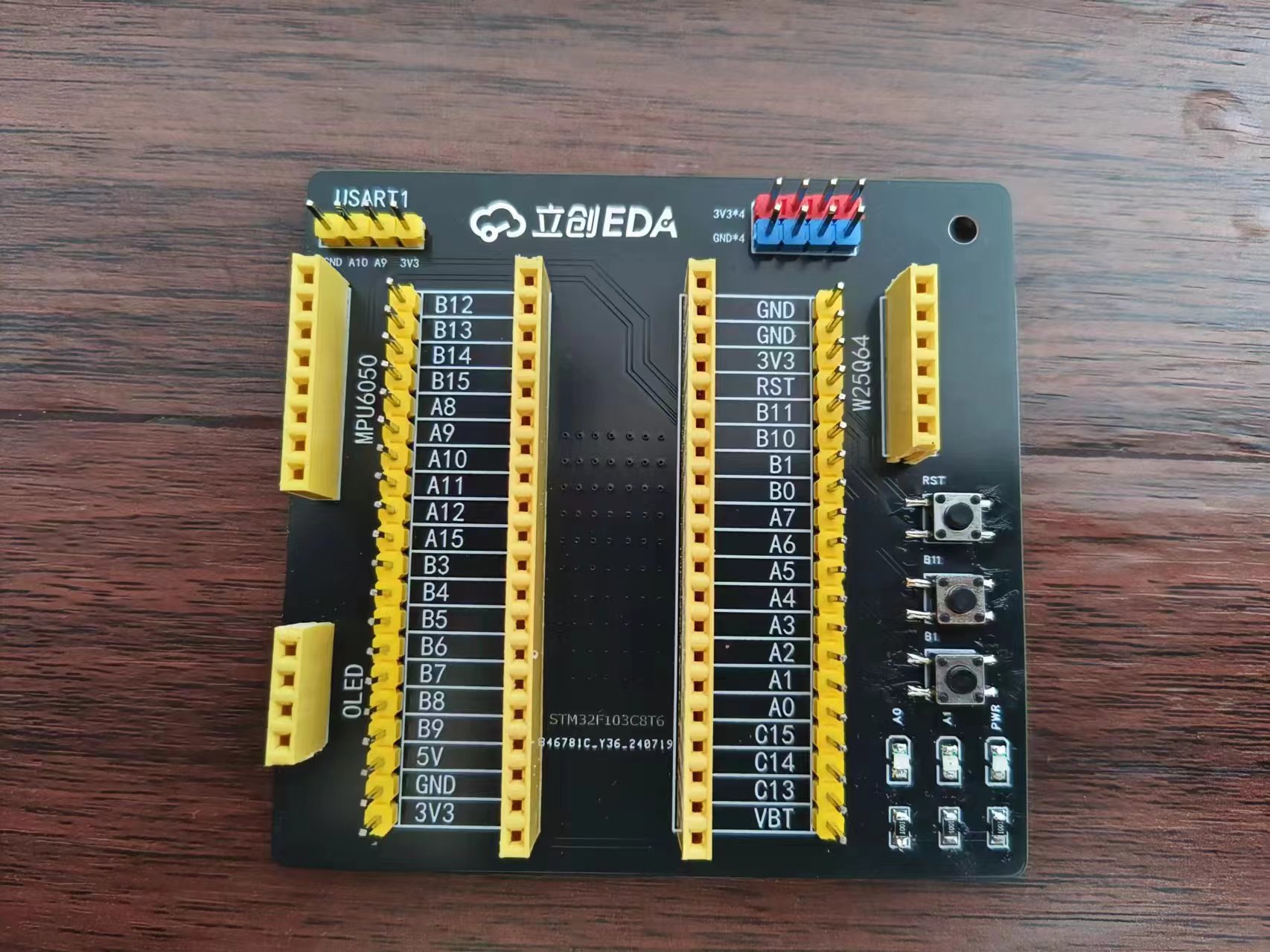
This STM32F103 expansion board is designed for use with Jiangxie Technology tutorials. The design philosophy emphasizes compactness and convenience, with all I/O ports exposed. The
exposed pin headers and headers can be used to connect to MPU6050, W25Q64, OLED, USART1, and 4 power supply pin pairs.
PADS_STM32F103 expansion board, compatible with Jiangxie Technology tutorials.zip
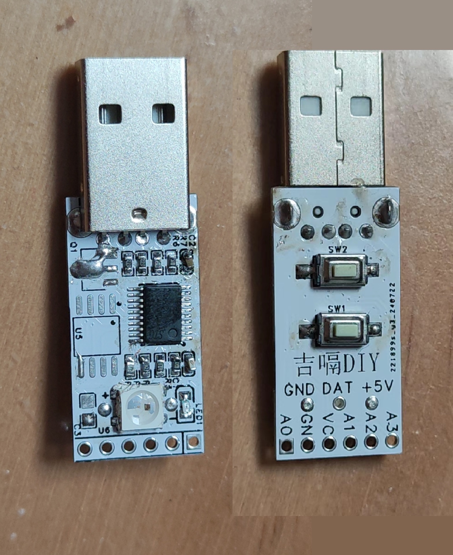
STC's USB keypad features integrated LED lights, a reserved OLED interface, and can also be used to solder an infrared head.
I. Team Introduction:
JiGe DIY is an electronics enthusiast who enjoys making various small electronic projects. Those interested in learning and exchanging ideas can search for "[JiGe DIY]" online.
II. Design Summary:
I've been using STC microcontrollers to make various gadgets. Recently, I've enjoyed tinkering with the USB function of STC microcontrollers. Seeing many USB examples on the STC official website, I decided to make a small board using STC. First, I'll implement a USB keyboard, and then I'll research implementing a USB flash drive.
III. Design Diagram:
The overall framework is simple, using a microcontroller as the core and adding a few peripherals. An OLED interface is provided.

IV. Hardware Circuit Composition :
The circuit is relatively small and simple.
1. Level Conversion: A 1117-3.3 converter is used to convert 5V to 3.3V to power the microcontroller and peripherals.
2. Indicator Lights: LED indicators are directly connected to the microcontroller's I/O ports for flashing operation prompts.
3. Memory Chip: W25Q series memory chips; all pins are connected to the microcontroller's I/O ports, allowing for various software-configurable functions.
4. Colorful LEDs: A single WS2812B LED can be designed to create a cool, colorful display on the board.
5. Expansion Interfaces: A row of 2.54mm connectors is provided at the rear of the board, allowing for the soldering of OLED displays, infrared receivers, or other peripherals.
V. Physical Demonstration VI
. Program and Related Expansion
Programs: The program is based on the official documentation with slight modifications. You can also make other modifications and experiments according to your own needs.
Because of the reserved expansion interfaces, the program can be freely adjusted.
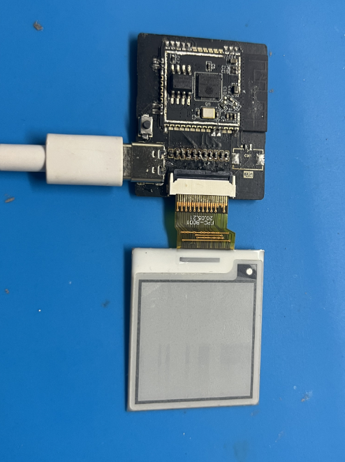
The motherboard is built to a 1:1 scale with the Waveshare 1.54-inch e-ink screen, with a perfect fit between the screen and motherboard. It supports battery power and Bluetooth/WiFi image transmission. It's comparable
to the development board sold for 77 yuan on the Waveshare official website.
01 Introduction
Wouldn't you like to try making an e-ink screen (also called a paper-like screen) driver board using a free PCB?
This product directly rivals the driver board sold for 77 RMB on the Waveshare website (the codes for both driver boards are interchangeable).
This board can transfer images via a mobile app or computer webpage (the only drawback is that these two transfer methods can only be used one at a time, not simultaneously).
It supports charging via a Type-A to Type-C interface data cable, and the LED turns off when the battery is fully charged.
It also supports the entire Waveshare e-ink screen series (which can be expanded to include: clocks, desktop ornaments, e-books, calendars, etc.).
02 Inspiration
A friend gave me an e-ink screen, which sparked my curiosity.

So, I briefly browsed through some open-source projects online...
"Forget it, none of them are to my liking."
"I'll just make one myself."
And so, this article you're reading now came about...
03 Overall Parameters
WiFi Standard
802.11b/g/n
Bluetooth Standard
Classic Bluetooth (BR/EDR) and Bluetooth Low Energy (BLE)
Communication Interface
4-wire SPI (default)
Operating Voltage
3.2V-5V
Operating Current
20mA ~ 150mA
Dimensions
3.1×3.7
Click to view [Supported Screen List]
04 Hardware Design

To ensure signal strength, a slot was made at the top of the PCB.
In my design, I made the Type-C interface protrude slightly outwards, which will make it easier to design the casing later.
You can directly use a free PCB for board making; I recommend a thickness of 1mm and black solder mask.

(Free stuff is always better!)
05 Soldering/Making Tutorial
For board making, I recommend a thickness of 1.0mm and black solder mask; gold plating is best if possible (not using gold plating won't affect soldering or actual use).
If you want to make this, you definitely need to know how to solder; if you don't know how to solder... well, forget it.
I recommend using a soldering station and a hot air gun, as they are quite convenient.
Use the soldering station for the bottom (the components are small and varied; a hot air gun could easily blow them away). Use
a hot air gun for the top; I recommend using "room temperature leaded solder paste" for better results.
Battery model: 503035. I bought 600mAh batteries for 8.1 yuan each, and also asked the seller to provide 1.25mm terminals.
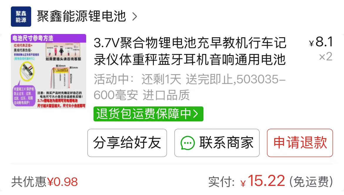
[Click here for the same battery] (ps: I'm not getting paid for advertising; their service is genuinely good).
06 The code burning
program comes in two versions: WiFi connection and Bluetooth connection. You can only choose one.
Before burning, please ensure your computer has the CH340 serial port driver installed. If not, please download "CH340 serial port driver.exe" from the attachment and install it.
A: Bluetooth Connection Tutorial
1. Download the two files "esp32 e-ink screen - Bluetooth connection.zip" and "ESP32 offline driver.exe" from the attachment.
2. Install Arduino IDE on your computer
. 3. Install the ESP32 offline driver
. 4. Unzip the compressed package
. 5. Open "Loader_esp32bt.ino" in the "Loader_esp32bt" folder.
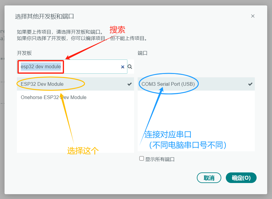
6. Click: Select Development Board

. 7. Connect the soldered board to the computer using a USB cable, search for "esp32 dev module", and click it. Select the port number corresponding to the development board on the right.
8. Click "Upload" in the upper left corner of the program .

9. Wait for the upload to complete, then click the reset button on the module to restart it.
10. Install the APK on your mobile phone (in the compressed package).
11. Open the app.
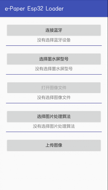
12. Done! Connect and use it in the app!
13. Bluetooth connection app related issues explanation (with pictures)

B: WiFi connection tutorial
1. Download the two files "esp32 e-ink screen - WiFi connection.zip" and "ESP32 offline driver.exe" from the attachment.
2. Install Arduino IDE on your computer
. 3. Install the ESP32 offline driver
. 4. Unzip the compressed file
. 5. Open "Loader_esp32wf.ino" in the "Loader_esp32wf" folder.
6. Complete steps 5-7 of the "Bluetooth Connection Tutorial" (I'm too lazy to write them again), and upload the program to the development board.
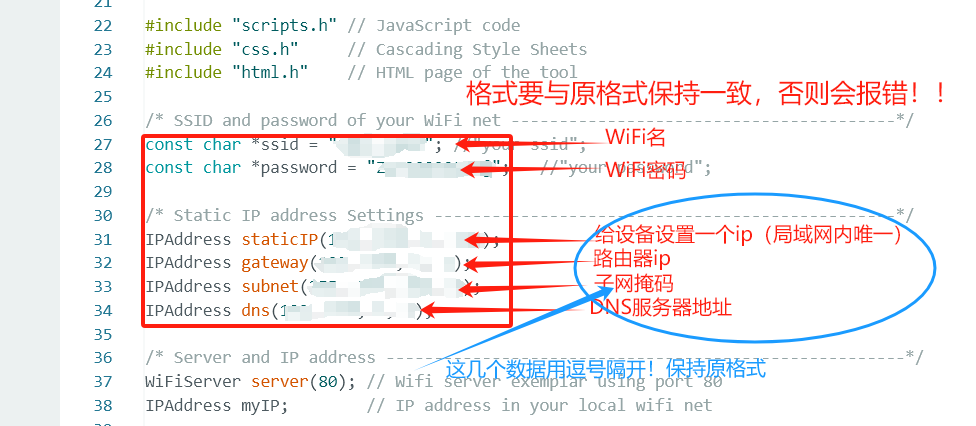
7. As shown in the image, find "srvr.h" at the top of the Arduino and click it
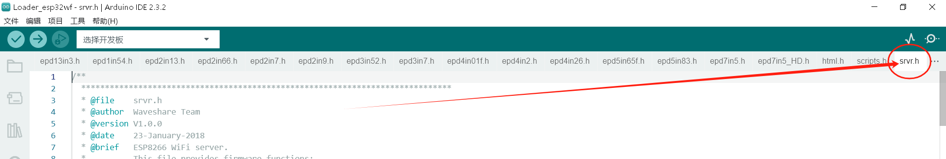
. 8. Scroll down to line 26. Modify the data in lines 27-34 according to your network conditions.
9. Complete steps 7-9 of the "Bluetooth Connection Tutorial" (I'm too lazy to write them again).
10. Access the IP address you just set for the device in your browser. Success!

11. WiFi Connection App Related Issues Explained (with Pictures)
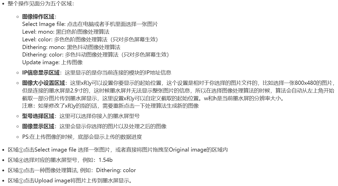
If you're still unsure... you can check out the official WaveShare tutorial: https://www.waveshare.net/shop/e-Paper-ESP32-Driver-Board.htm
(The official tutorial is probably more detailed. For the flashing code, I recommend using the one I uploaded in the attachment; I've translated it into Chinese for a better reading experience.)
This concludes the article. If you have any questions or valuable feedback, you can click here to get my contact information.

ESP32 e-ink screen - Bluetooth connection.zip
esp32 e-ink screen - Wi-Fi connection.zip
ESP32 offline driver.exe.exe
CH340 serial port driver.exe
Project file - 1.54-inch e-ink screen driver board.epro
Plate making file - 1.54-inch e-ink screen driver board.zip
PDF_1.54-inch E-ink Screen Driver Board.zip
Altium 1.54-inch E-ink Screen Driver Board.zip
PADS 1.54-inch E-ink Screen Driver Board.zip
BOM_1.54-inch E-ink Screen Driver Board.xlsx
93461
Button-operated sound toys
If it's just a toy, there's not much to say.
Recently, there have been many button-operated sound toys on Bilibili,
and some friends also wanted to customize the audio,
so this project was created. It makes a sound
when pressed, with not many functions.
The speaker was just randomly selected from the library; you don't need to buy according to the BOM list (but LCSC's online store is convenient and hassle-free). The chip used is the SZY13P005J chip; you can buy it by searching for "audio IC" on Taobao (the seller provides free burning and a capacitor speaker). (Very durable)
. It's very cheap and affordable. LCSC provides 5 PCBs at a time, and the IC seller provides 5 ICs at a time (to prevent clumsy attempts). Soldering is extremely difficult (you can even just plug it in without soldering). Suitable for beginners to replicate.
Detailed tutorials (to be released within a week) can be found on Bilibili: @XC若雨 (follow 若雨喵, thank you!).
QQ image 20240728221432.jpg
QQ image 20240728221411.jpg
QQ image 20240728221423.jpg
QQ Video 20240728223334.mp4
PDF_Button-Sounding Toy.zip
Altium_Button Sound Toy.zip
PADS_Button Sound Toy.zip
BOM_Button-activated Sound Toys.xlsx
93462
STC32G12K128 Minimum System Development Board
The STC32G12K128 series microcontroller is a 32-bit microcontroller with a wide operating voltage range launched by STC in 2022. This course provides a suggested system development board based on this microcontroller for hands-on learning and project implementation.
I. Product Introduction. The STC32G12K128 series microcontroller is a 32-bit microcontroller with a wide operating voltage range launched by STC in 2022. This course uses this microcontroller to build a suggested system development board for hands-on project learning. The chip's peripheral functions are as follows:
4 serial ports;
5 timers;
8-channel 16-bit advanced PWM;
15-channel 12-bit ADC;
2-channel CAN bus function units;
1-channel I2C serial bus;
supports DMA (SPI/I2C/ADC/UART/LCM).
All I/O ports support interrupts except for the interrupt pin.
II. Board Functions 1. One CAN bus interface, using TI's SN65HVD230DR as the CAN transceiver for simple CAN communication. 2. One WS2812 LED. 3. One RGBW LED. 4. One 4-digit common anode LED display. 5. One 1.3-inch TFT LCD display interface, which can also be used for OLED displays. 6. One NTC temperature sensor and one light sensor.
7. 20 LED beads for a running light display. 8. One power switch.
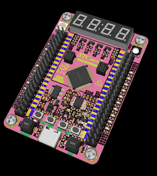
III. Rendering
1: 3D view and actual image of the development board PCB front.
IV. Development Board Circuit Description and Usage:
1. The development board has a power-on switch circuit. When the button is pressed, the system will power on. When the MCU has no program, press the P3.2 button and then press the power button to power on the MCU. The computer can then recognize the chip and enter the programming mode. When the system has a program, it can detect power-on and pull P1.4 high to power on the system. Powering off can be done by detecting the button status on P1.6 and pulling P1.4 low
. 2. The development board has 10 LEDs on each side, orange on the left and blue on the right.

3. The top of the development board has a 4-digit common anode digital tube, which can be connected to an external clock module to display the time and can be used for other digital displays.

4. One CAN bus interface, pre-installed on the pin header for easy debugging.

5. The board uses one RGBW LED for display, and one WS2812 LED on the right side for driving different LED effects in different scenarios.

6. The board uses a 1.3-inch TFT display to drive the SPI-driven color screen display.

Currently, only program download, flow lights, and button functions have been tested. Other functions have not been tested and will be added and updated later when time permits.
PDF_STC32G12K128 Minimal System Development Board.zip
Altium_STC32G12K128 Minimal System Development Board.zip
PADS_STC32G12K128 Minimal System Development Board.zip
BOM_STC32G12K128 Minimum System Development Board.xlsx
93463
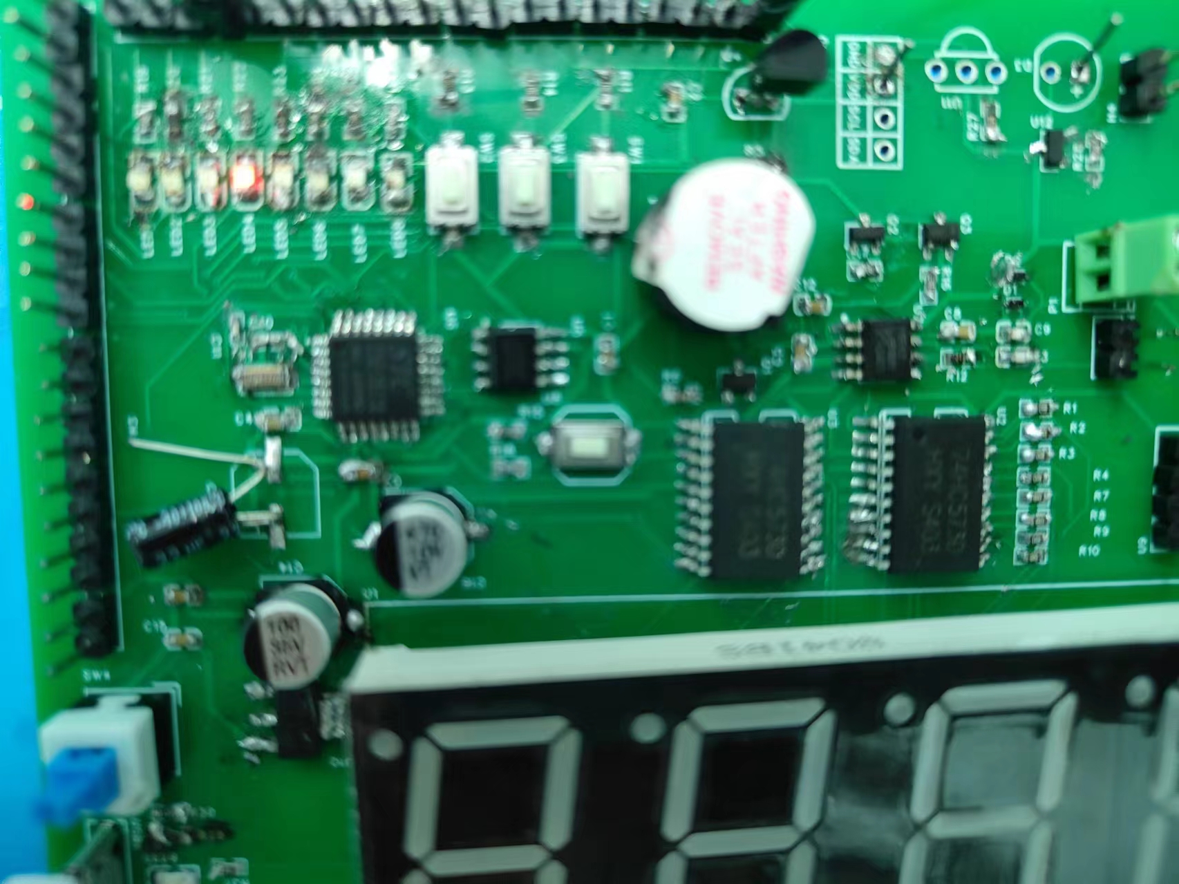
STC32 Development Board - Beginner's Guide
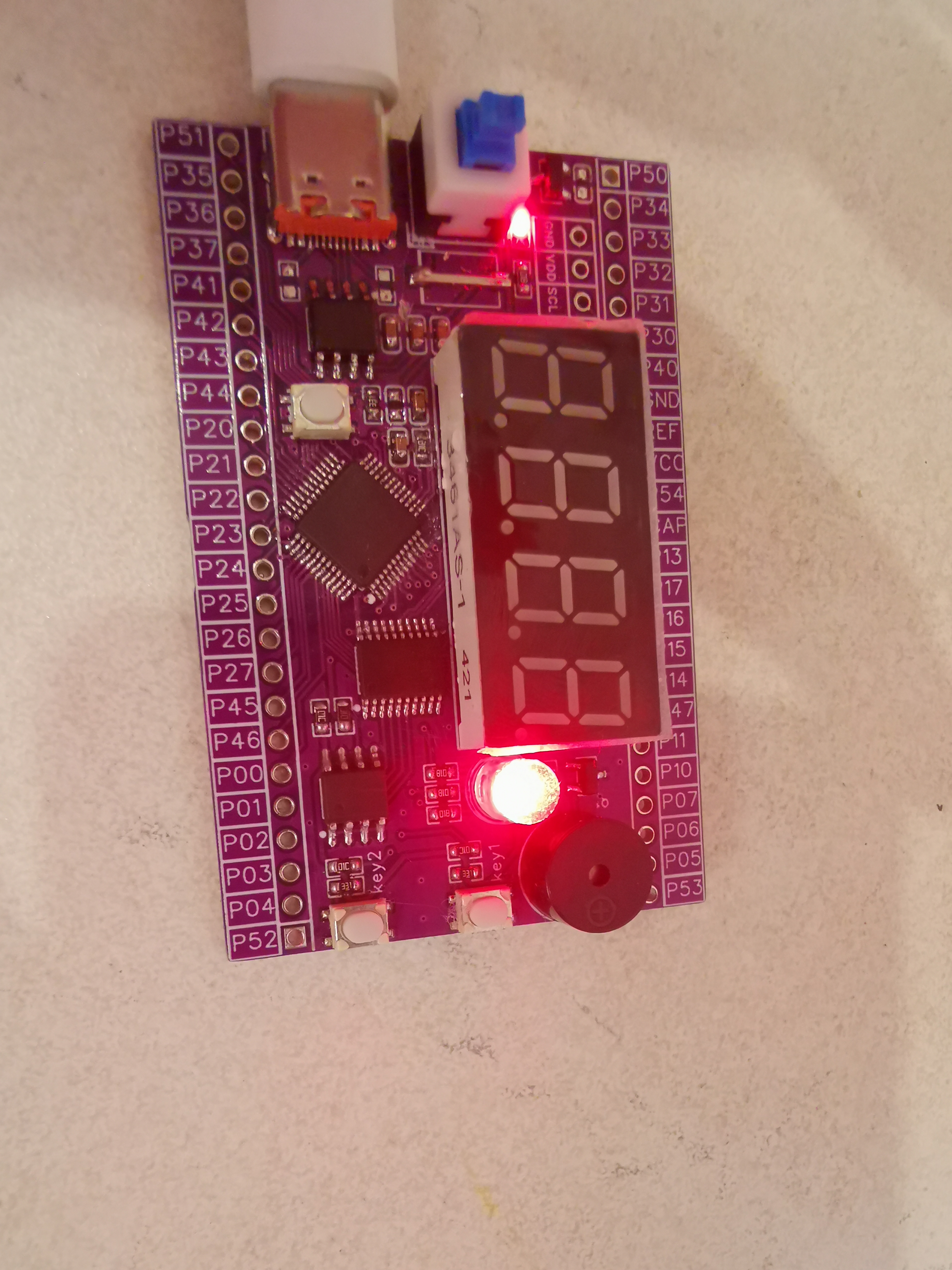
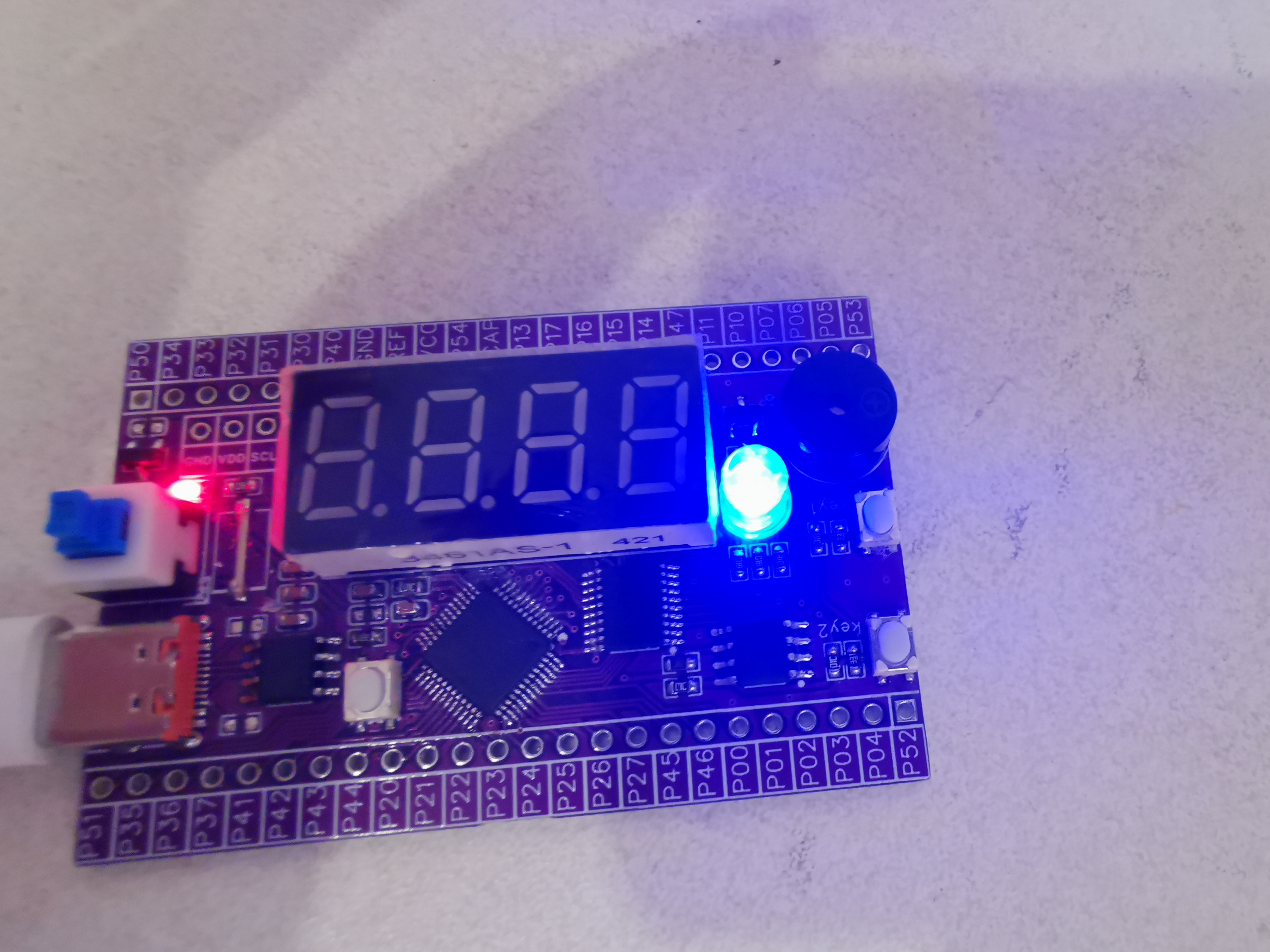
A beginner is trying to design an STC32 development board to learn about embedded
development boards with "all pins exposed," including a digital display, a tri-color LED, a power indicator, a buzzer, two buttons, and a reset button.
The STC32G12K128 development board
uses the STC32G12K128 core, LQFN-48 package, and all pins are exposed. The onboard peripherals
are mainly based on the development board by the author Future Electronics Studio on the open-source platform (https://oshwhub.com/wei-lai-dian-zi-gong-zuo-shi/zui-xiao-xi-tong-stc32g12k128). A digital tube, LEDs, and a buzzer have also been added.
Since this is the first time designing a PCB, the first two versions had errors and were unusable. Fortunately, JLCPCB provides two free trials per month, plus a prototyping voucher, which allowed me to barely create a usable development board.
Currently, the LED lighting experiment has been implemented. The digital tube circuit still has some issues, which will be further improved later. Below are pictures of the actual product; a demonstration video is attached.
VID_20240728_203110.mp4
PDF_stc32 development board - beginner version.zip
Altium_stc32 Development Board - Beginner's Version.zip
PADS_stc32 Development Board - Beginner's Version.zip
BOM_stc32 Development Board - Beginner's Guide.xlsx
93464
electronic
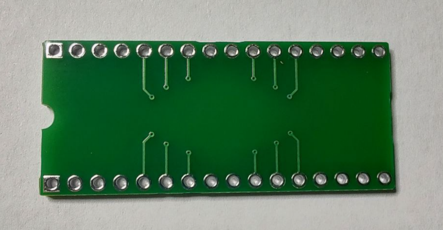
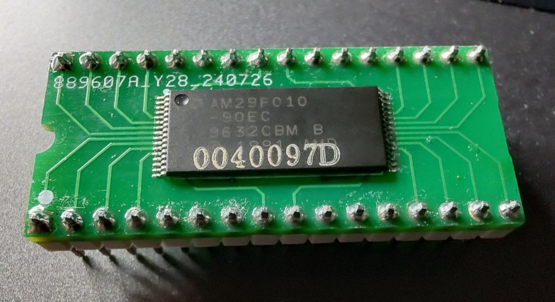
 for the Air780EX4G module require a voltage of 3.8V to 4.2V. The corresponding power conversion design is available in the Air's hardware design documentation. This is from a training assignment; for convenience, I used leftover 1N4148 diodes from making a mechanical keyboard to achieve 3.8V through diode voltage drop (the voltage drop of a single 1N4148 straight diode is approximately 0.6V, depending on the diode's datasheet). All the surface-mount packages I used are 0805, except for the 1N4148 diodes.
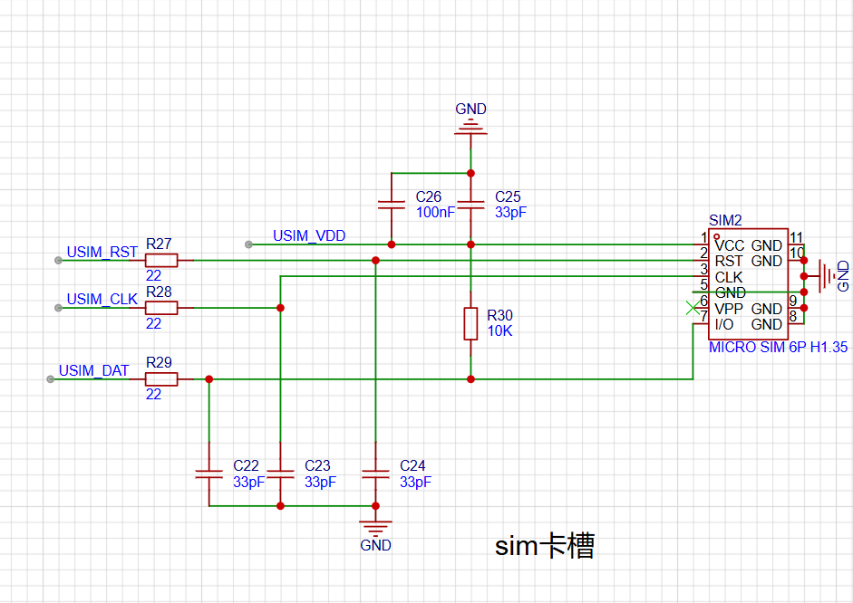
 Note that because this was just a training assignment, the school provided limited components. There was originally grounding protection, but the teacher removed it after reviewing my design. There are also four Zener diodes; add them according to your needs.
  and physical demonstration notes:
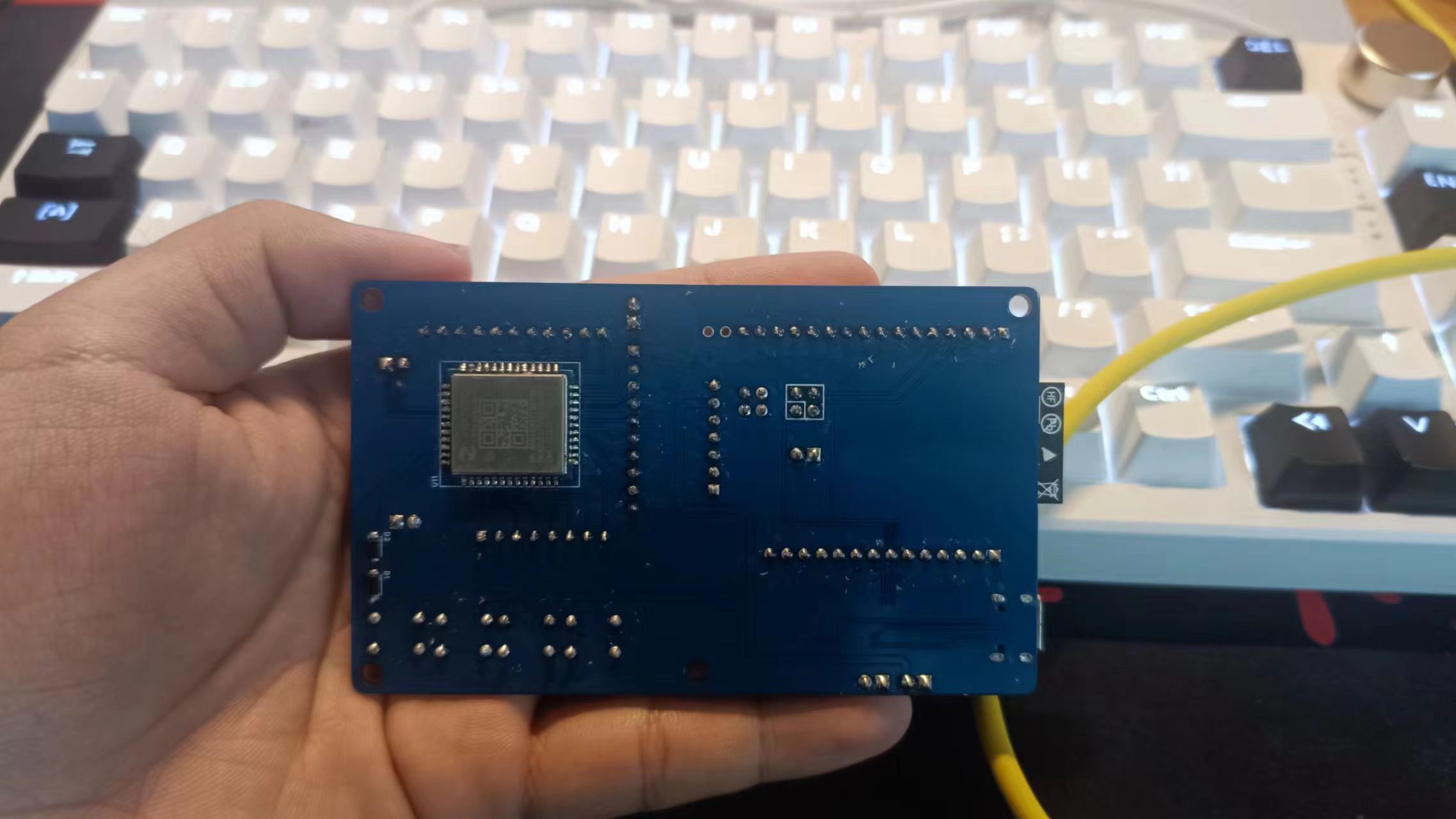
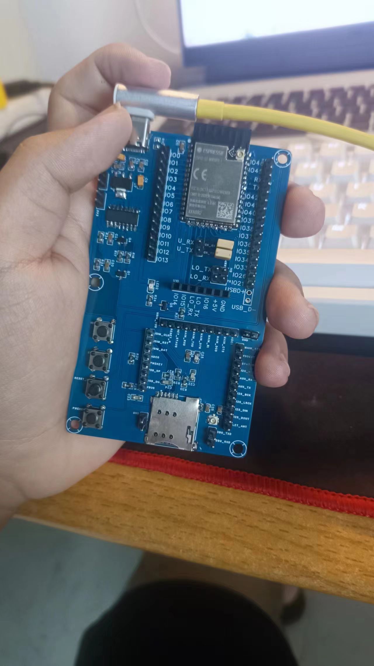
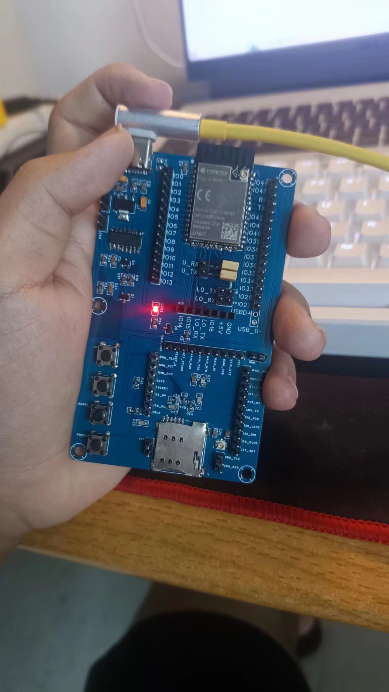 I forgot that the ESP32S2 has a full-featured USB module when I was drawing the schematic, but I remembered it while soldering. If you want to use this full-featured module... You can add another 5V header pin below the USB-D pin when drawing the diagram; this will create a solder hole when printing. Alternatively, you can add a Type-C female connector. Slightly adjusting the grounding pin position should be sufficient. When I was doing this practical assignment, the teacher provided a tantalum capacitor instead of a 10nF capacitor, which has positive and negative terminals. No
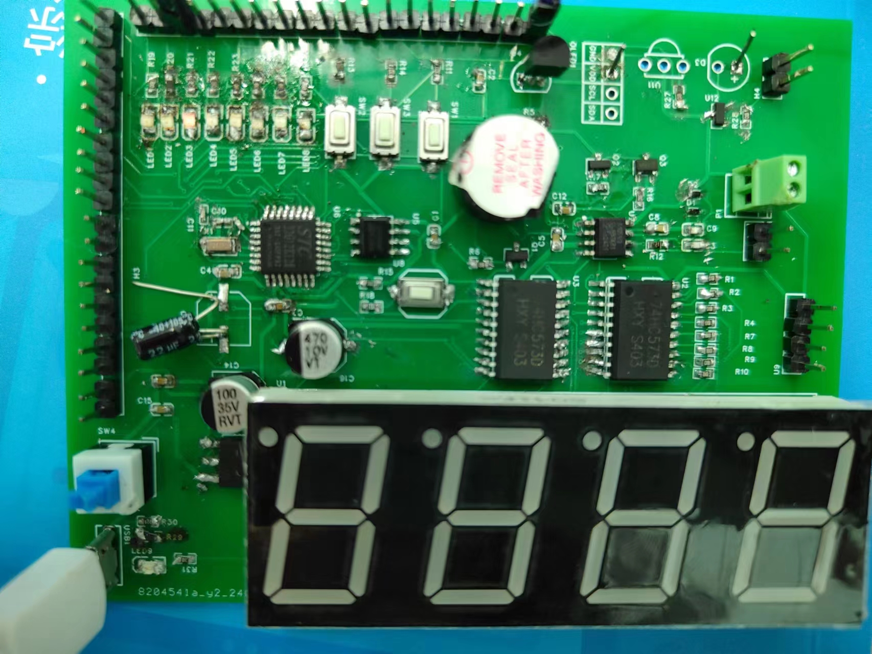
 with a mouse; the board itself is smaller than half the size of a mouse
  .
.  It's an
 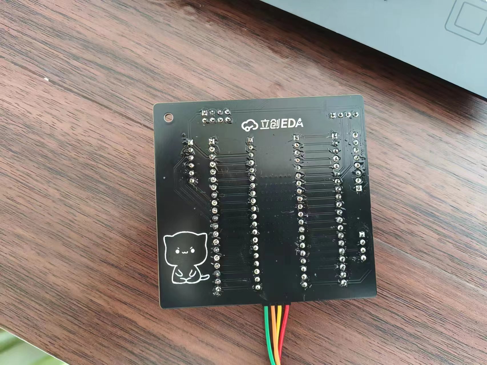 STM32F103 expansion board, suitable for Jiangxie Technology tutorials. The design philosophy is compactness and convenience. All I/O ports are brought out,


 京公网安备 11010802033920号

 FZ2C330KR


