I. Why Design This Charger:
Six months ago, I purchased a knock-off Xiaomi 120W charger from a seafood market. It could activate the Xiaomi 120W gold standard, but in actual testing, the maximum output power was only 20W, which was extremely poor. Upon disassembly, the internal components were extremely rudimentary, even including a large iron counterweight.
At the time, I was studying flyback power supply design and wondered if I could use the knock-off charger's casing to design my own circuit board to replicate the Xiaomi 120W charger, while also supporting continuous PD output of 100W. This led to this project.
II. Charger Architecture
: This design uses a QR quasi-resonant flyback + synchronous rectification architecture. The maximum output is designed to be 20V/6A, with a maximum conversion efficiency of 94.2% and a maximum switching frequency of 130kHz. In terms of charging protocols, it supports PD3.0, Xiaomi 120W proprietary protocol, QC3.0, etc.
III. Components
The AC/CDC chip uses Dongke Semiconductor's DK075GCD. The DK075GCD is a quasi-resonant flyback GaN chip with integrated 160mΩ on-resistance and 700V GaN switching transistor.
The synchronous rectification uses Dongke Semiconductor's DK100R05VT, which integrates a 5mΩ on-resistance and 100V NMOS switching transistor.
The protocol chip is a Weltrend WT6633P salvaged from a Xiaomi 120W charger, supporting Xiaomi's 120W proprietary protocol. (Note: The reference WT6633P does not have the program for burning the Xiaomi 120W proprietary protocol, so it does not support the Xiaomi 120W protocol.)
It has four 33uF/400V electrolytic capacitors at the input and two 1000uF/25V solid-state capacitors at the output. Ripple hasn't been measured yet, but this capacitor configuration is quite luxurious, so the output voltage ripple should be very low.
IV. Test Report:
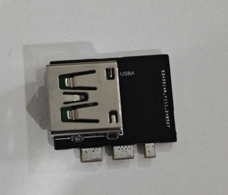
Due to laziness, the board I designed at the beginning of the year has only recently started debugging. The power section has just been debugged, and I've only roughly looked at the specific performance parameters. To be honest, it's pretty good, better than expected, but I haven't recorded the data. Detailed efficiency, temperature rise, ripple, protocol, and other test data, as well as the BOM, will be uploaded after the testing is completed. Here are some pictures of the actual board (it's a bit dirty because it wasn't cleaned properly QvQ).
I've always wanted to make a lamp, and since there was a promotion, I started making one.
1. Project Function Introduction
: The function is very simple; it's just a dual-color temperature fill light. Due to time constraints, the color temperature adjustment function hasn't been implemented yet; currently, only brightness adjustment is possible.
2. Project Attributes:
This is the second time participating in LCSC's event, this time in collaboration with STC.
3. Open Source Parts
: The hardware is open source.
4. Hardware Introduction:
The main controller uses the STC8H8K64U microcontroller, as required by LCSC's official specifications. This microcontroller requires very little external circuitry to function properly; it doesn't even need a crystal oscillator, only the internal clock source of the MCU. The light driver uses the domestic LGS63032 driver; you can apply for a sample from their website. This chip supports a maximum power input of 60V and a minimum of 3V, and it's an automatic boost converter, which works very well. Originally, there was also a battery management chip, but I don't know if it's a design flaw or a problem with my soldering (it seems the bottom EP grounding pad wasn't properly grounded, resulting in an output voltage of only 2.3V; after DC-DC step-down, the voltage is even less than 1V). I had no choice but to remove the chip.
I won't go into detail about the LED board; it's a very simple wiring system. It consists of 10 LEDs strung together as one LED group. There are two such groups, one for cool color temperature and one for warm color temperature. The
interaction is simple, with three buttons: power on/off, increase brightness, and decrease brightness. Color temperature adjustment functionality might be added later, or it might not. Also, I have to say, STC's library functions are rather rudimentary, which significantly increases the development difficulty.

PDF_STC-based fill light.zip
Altium_STC-based fill light.zip
PADS_STC-based fill light.zip
BOM_STC-based fill light.xlsx
93471
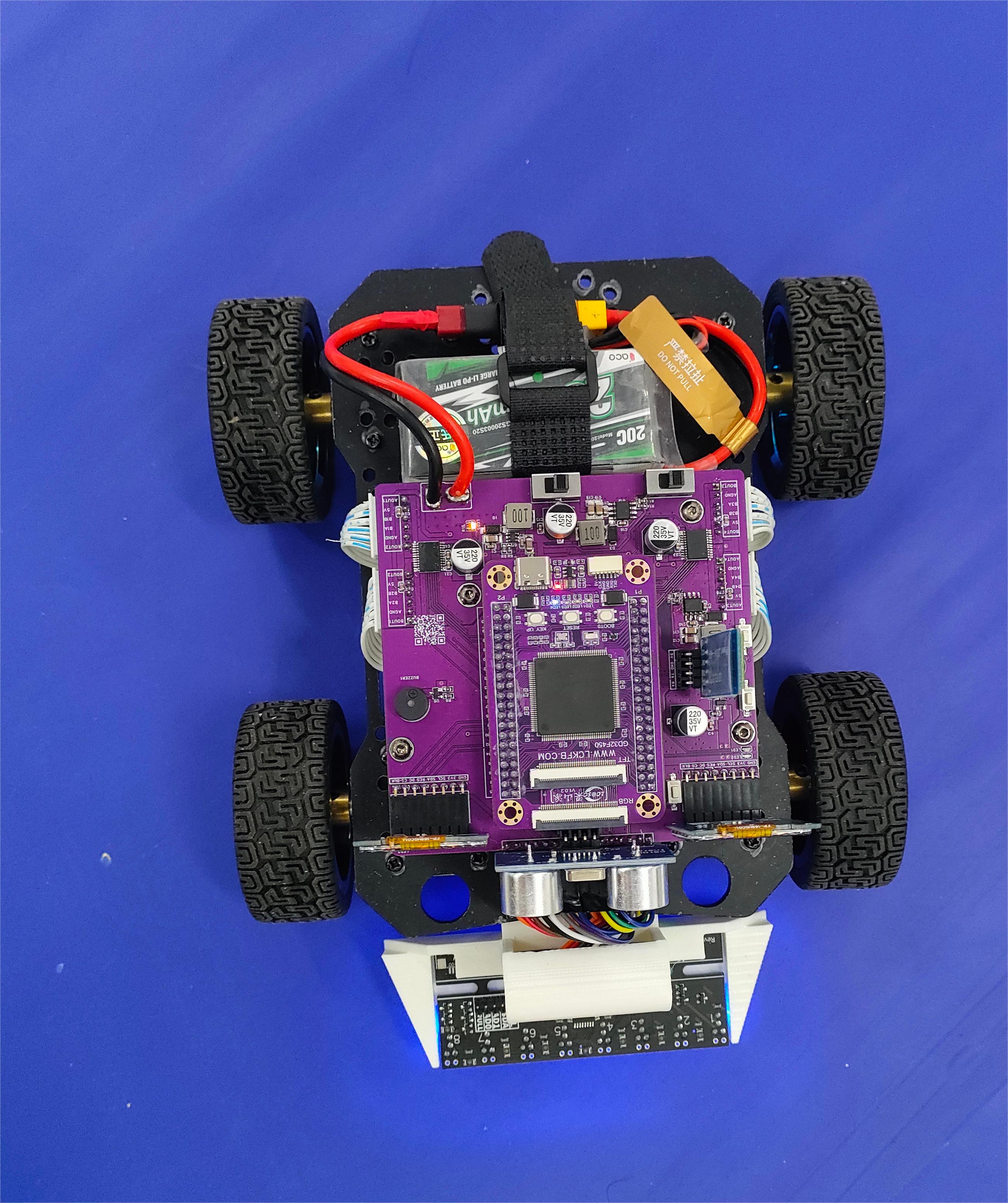
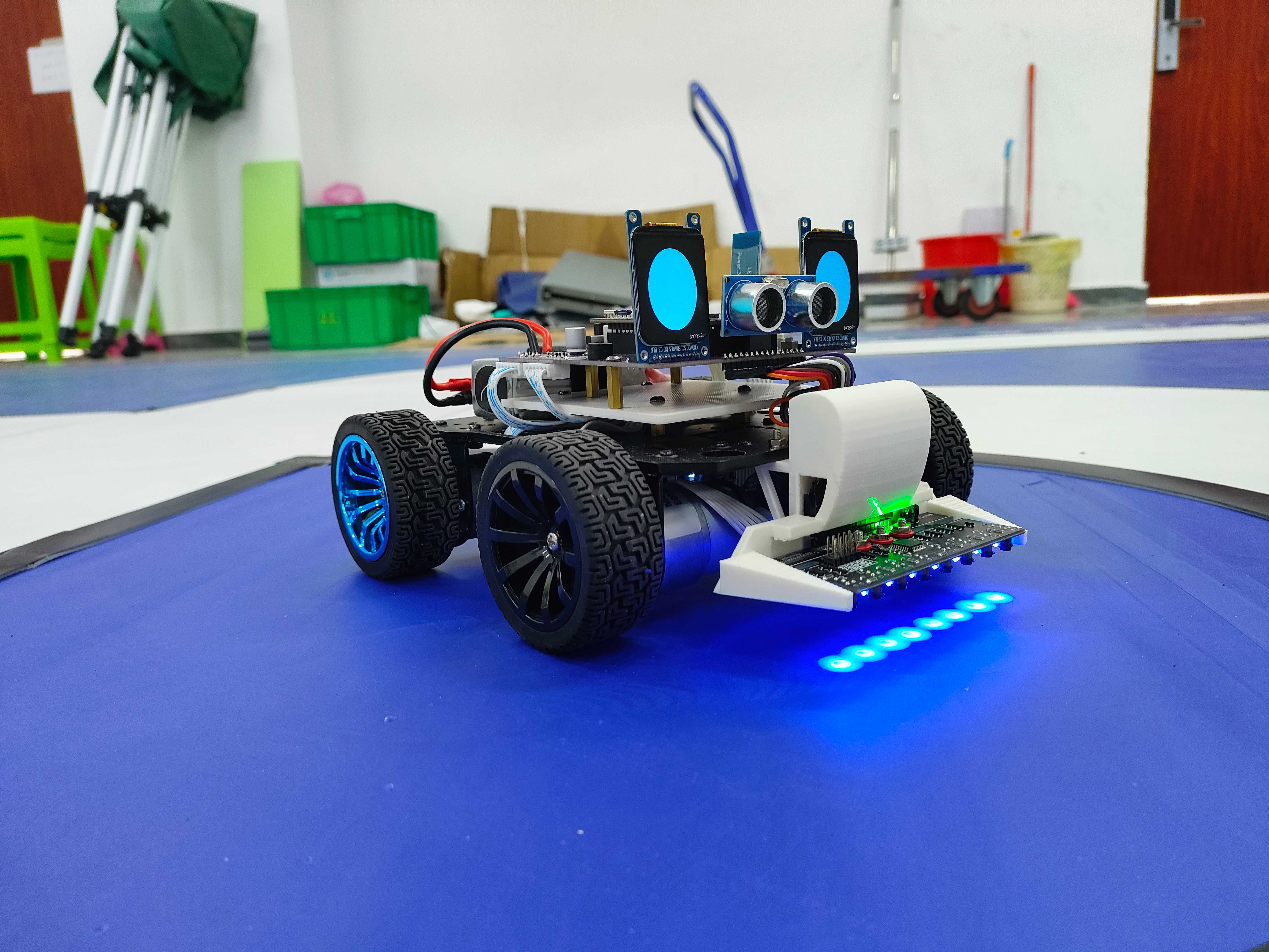
Smart car
Based on the Liangshan School's four-wheeled vehicles, the vehicles can be controlled via Bluetooth, including tracking and obstacle avoidance.
I. Project Name:
- Smart Car Design Based on LCSC Liangshan School
- Hardware design is described below, and software design code has been uploaded to Attachment
II. Objectives:
- Design a Bluetooth-controlled car with line-following and obstacle avoidance functions, and to give the car expressions and status displays.
- Originally, I also wanted to use a radar monitoring sensor to track human movement, but due to module limitations, I was unable to use it.
III. Function Introduction:
- This project uses Bluetooth remote control to move the car in direction. It can also switch to line-following mode, obstacle avoidance mode, etc. via Bluetooth.
IV. Project Description
Hardware used in the project:
- LCSC Liangshanpai
- Mainboard of the car (integrating voltage regulator module and TB6612 motor driver)
- Bluetooth module
- Ultrasonic module
- Ganwei eight-channel grayscale sensor module
- Buzzer
- LEDs (SMD + DIP)
- Four DC geared motors (Lunqu Technology MG513 DC geared motor with Hall sensor)
- Two 240*280 TFT LCD screens
V. Hardware Design
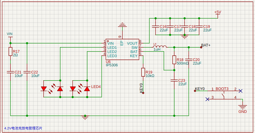
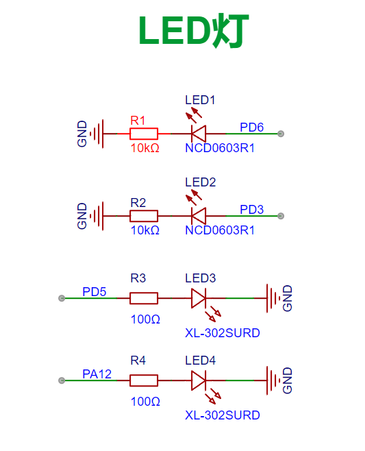
1. LED lights
![image.png]
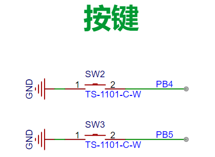
2. Buttons
![image.png]
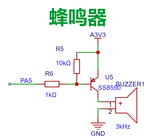
3. Buzzer
![image.png]
4. Line-following module interface
![image.png]
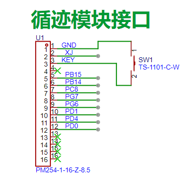
Here XJ is 5V. The button design is based on the design requirements given by Ganwei Technology.
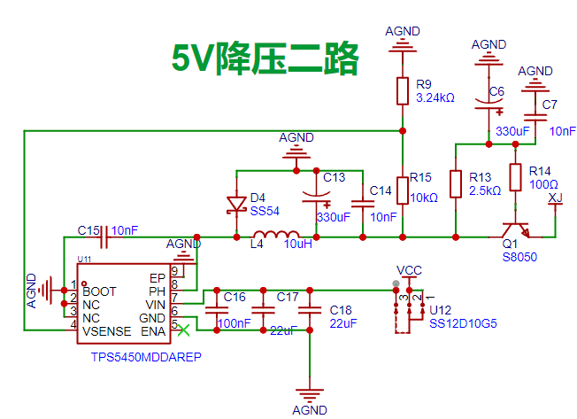
5.

DC-DC 5V Step-Down Circuit Both circuits use 5V step -down technology
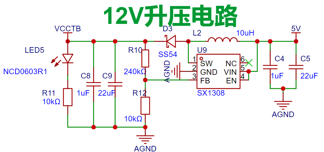
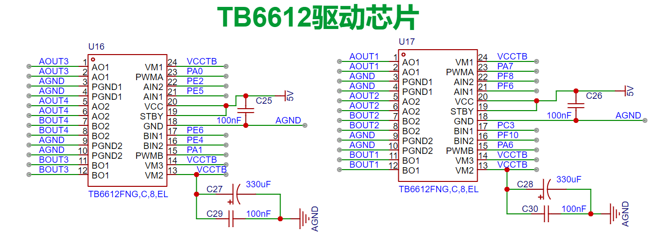
. A single 5V circuit powers the eight grayscale sensors. Ensure the 5V power supply to the sensors is stable. Do not share a 5V power supply with inductive loads such as servos, motors, or horns. Inductive loads generate very high voltages when current changes abruptly, which can easily burn out the sensors. The voltage divider resistors in the circuit need to be adjusted according to the actual situation. 6. DC-DC 12V Boost Circuit This circuit uses the SX1308 boost chip. The voltage divider resistors in the circuit need to be adjusted according to the actual situation. 7. LDO 3V3 voltage regulator circuit ![image.png] 8. TB6612 driver circuit ![image.png] 9. Motor interface circuit ![image.png] ![IMG20240720155028.jpg] ![IMG20240720155036.jpg] ![WeChat image_20240721085657(1).jpg] VI. Skills Mastery: - Through this project, I learned some code logic control. - I learned how to display desired information on an LCD. - I learned and mastered DC-DC buck-boost circuits. - Shortcomings - I could not use the SDIO on the Liangshanpai platform to read data and then display the data information in the SD card on the LCD. Finally, I got stuck on reading the information from the SD card, and the read data was displayed as a garbled screen on the LCD. VII. Problems Encountered and Solutions - For PWM Output: - Testing revealed that only port A could output a PWM signal to drive the motor; other pins could not. The reason for this was unknown. The hardware pins were then modified, and all were changed to port A. - For Bluetooth Control of the Car's Movement: - In the initial design phase, Bluetooth data transmission caused the car to enter line-following mode. Two situations occurred: first, the car only executed one line-following function; second, it could not exit line-following mode. Through web searches and AI queries, combined with the provided code, the logic was modified, and the desired result was achieved. - For Initialization of the Two LCDs: - Modifying the macro definitions failed to achieve the desired functionality and resulted in errors. The macro definitions had to be discarded, and modifications were made directly to the .c file.


Bluetooth remote control zzxc.zip
July 21(2)(4).mp4
PDF_Smart Car.zip
Altium_SmartCar.zip
PADS_Smart Car.zip
BOM_Smart Car.xlsx
93473
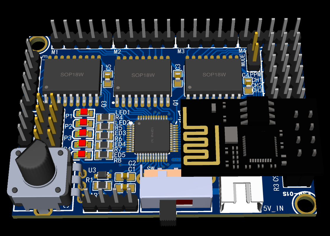
Six-axis robotic arm
My self-designed six-axis robotic arm controller and 3D model
The main chip uses the STC8G2K64S4, which can control 5 five-wire four-phase stepper motors and 1 servo motor
. It features an onboard ESP8266-01 interface for network control.
It also has 4 onboard digital input interfaces driven by ULN2803,
supporting one PPM signal and 12 digital inputs.
An onboard ADC input is also included. The 3D model source files and related code are open-sourced on Gitee: my_robot-I: Homemade Robotic Arm Related Materials (gitee.com)
VID_20240728_144812.mp4
PDF_Six-Axis Robotic Arm.zip
Altium 6-axis robotic arm.zip
PADS_Six-Axis Robotic Arm.zip
BOM_Six-Axis Robotic Arm.xlsx
93474
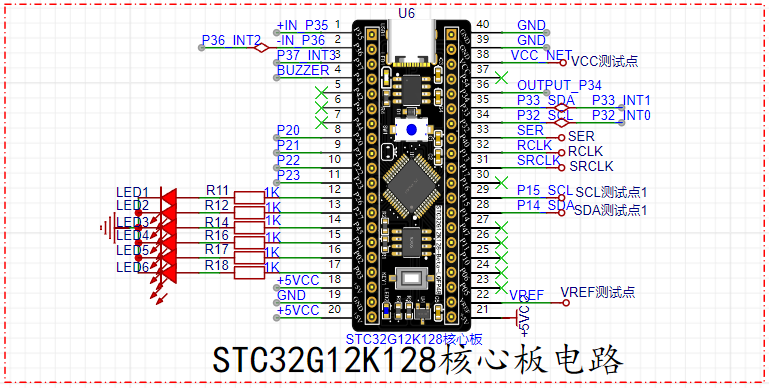
STC32G12K128 Minimum Core Board + Expansion Board
This project produced an STC32G12K128 minimum core board. The onboard CH340N can be used to download code via serial port, and the onboard M24C02 is used to store the microcontroller's data. An expansion baseboard was also made for verification. The minimum core board circuit has been verified and can be used normally.
The STC32G12K128 core board and expansion board : Compared to the earlier STC89C51/90C51 series learning boards, the STC32G12K128
core
board boasts significantly more powerful main control chips. For example, performance optimizations and the inclusion of STC32 series chips result in higher performance, making it suitable for handling complex application requirements. Rich peripheral interfaces: The core board typically provides a rich set of peripheral interfaces, such as GPIO (General Purpose Input/Output), UART (Serial Communication Interface), SPI (Serial Peripheral Interface), and I2C (Serial Bus Interface), facilitating connections to various sensors, displays, and other external devices. Low power consumption design: The STC32 series chips are known for their low power consumption, making them suitable for applications with strict power requirements, such as battery-powered devices or devices requiring long-term operation. Extensive development support: The STC series chips have a complete development toolchain and community support, allowing developers to quickly get started and obtain technical support and solutions. Cost-effectiveness: The STC32G12K128 core board typically offers high cost-effectiveness, making it suitable for cost-sensitive projects and applications. These advantages make the STC32G12K128 core board competitive in embedded system development, especially in scenarios requiring high performance, low power consumption, and cost-effectiveness.
The hardware circuit schematic design utilizes
the STC32G12K128 microcontroller

, a high-performance, low-cost 32-bit microcontroller from STC Microelectronics. It boasts powerful performance, featuring a 32-bit ARM Cortex-M3 core with a clock speed of up to 72MHz, providing strong processing and computing capabilities suitable for handling complex algorithms and tasks. It offers rich peripheral interfaces, supporting multiple general-purpose timers, multi-channel ADCs and DACs, and abundant communication interfaces such as UART, SPI, and I2C, meeting the needs of various applications. Its low-power design employs advanced low-power design and technology, demonstrating excellent energy efficiency, making it ideal for applications requiring long-term operation or battery power. The device boasts ample storage space, featuring large-capacity Flash memory and SRAM, facilitating the storage of substantial amounts of program code and data. The
power-off reset circuit
utilizes a unique button. Observing the schematic reveals that when the button is pressed, VCC and +5V are disconnected, powering down the microcontroller. When the button is not pressed, VCC and +5V are connected. This button operates on reverse logic; when the POW button is pressed, the MCU's power supply network VCC rapidly loses power, allowing for efficient USB-HID communication and code downloading.

This method is also known as cold start mode. During a cold start, the internal components of the device operate at a lower temperature than during normal operation. High temperatures accelerate component aging and damage; therefore, cold starts help extend the lifespan of electronic components. Furthermore, cold starts reduce electromagnetic interference. The circuit exhibits higher stability during cold starts, with smoother current and voltage changes, which helps reduce electromagnetic interference generated during startup and improves the device's anti-interference capabilities. To improve system reliability, cold starts allow for more precise current and voltage control of devices during the initial operation phase, reducing the risk of damage caused by voltage transients and current surges during startup, thereby improving the overall system reliability and stability. Therefore, circuit cold starts offer significant advantages in energy efficiency, component lifespan, electromagnetic compatibility, and system reliability, making them a commonly used startup method in many electronic devices and system designs.
The Type-C interface circuit

uses a 16-pin TYPE-C port, supporting the USB 3.0 protocol for easy data transfer and download. The USB-to-
TTL
circuit typically converts the USB interface voltage (usually 5V) to the TTL level (usually 3.3V or 5V) used for serial communication, enabling communication with microcontrollers, single-chip microcomputers, or other electronic devices.

Considering the small size of this core board, the CH340N is used as the USB-to-serial chip in this circuit. The IN5819WS chip in the circuit primarily protects the computer hardware, preventing backflow and damage when the USB is plugged into the computer.
Here are some key features of a USB-to-TTL circuit: Voltage Conversion: Converts the USB 5V voltage to a voltage suitable for TTL logic levels, typically 3.3V or 5V. This conversion is necessary because many microcontrollers and microcontrollers use lower operating voltages (such as 3.3V), while USB usually provides 5V. USB Interface: Typically has a USB Type-A connector for direct insertion into the port of a computer or USB-powered device. TTL Interface: Typically has a pin header connector with pin markings for connecting to the serial communication pins (such as TX, RX, and ground) of the target device (such as a microcontroller). Chip Integration: Typically uses a USB-to-serial (UART) chip, such as CH340 or CP2102, which can handle protocol conversion between USB and serial communication and support virtual COM port drivers. Driver Support: Most USB-to-TTL modules require a specific driver to be installed on the computer so that the operating system recognizes it as a virtual serial port (COM port), allowing communication with the target device via serial communication software. Speed and Stability: USB-to-TTL circuits typically support common serial communication rates, such as 9600 and 115200 baud rates, and offer good stability and reliability, making them suitable for various embedded system development and debugging tasks. They usually draw power from the USB bus, eliminating the need for an external power adapter, which makes them convenient to use and reduces additional power management requirements. Overall, USB-to-TTL circuits are commonly used tools in embedded development, facilitating communication and debugging with a computer and serving as a bridge between a USB host and TTL logic level devices. The M24C02
storage circuit
is a serial I2C bus interface electronic memory chip, typically used as an EEPROM (Electrically Erasable Programmable Read-Only Memory) to store data. Here is a basic introduction to the M24C02: Capacity and Organization: The M24C02 has a 2K-bit (256-byte) storage capacity. The memory is organized into 32 pages, with 8 bytes per page. This organization allows for page-by-page writing, improving write efficiency. Interface: The M24C02 communicates via the I2C bus, a two-wire serial communication protocol including a data line (SDA) and a clock line (SCL).
Features: Electrically Erasable and Programmable: EEPROM allows stored data to be erased and programmed electronically without removing the chip or using ultraviolet light. Low Power Consumption: The M24C02 features low power consumption, effectively reducing power consumption in standby mode. Write Protection: Supports hardware write protection, allowing the memory to be protected from accidental writes by setting specific bits. Lifespan: Offers a high number of erase/write cycles, typically exceeding 10,000 cycles; the actual lifespan depends on usage and conditions. Applications: The M24C02 is commonly used to store infrequently changing data such as device configuration information, system settings, and calibration data. Due to its small capacity, it is suitable for small embedded systems or sensor nodes. Operating Conditions: The M24C02 operates from 1.8V to 5.5V, suitable for the voltage requirements of various electronic devices. In summary, the M24C02 is a common small-capacity EEPROM chip suitable for applications requiring stable and reliable storage. It communicates with the main controller via a simple I2C interface, providing a convenient data storage solution. Regarding

the interactive button circuit
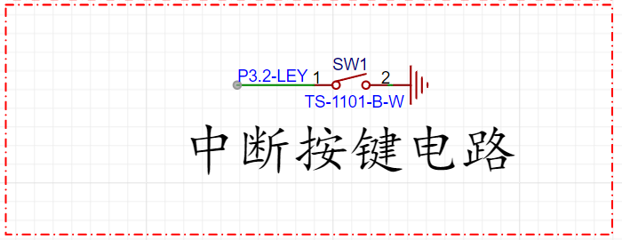
, since serial port code download is used, the STC USB-HID communication protocol is not used. Therefore, the interrupt button on the P32 microcontroller in this computer design functions as a regular button; when the P32 detects a falling edge, it triggers an interrupt and executes the interrupt instruction.
Reference voltage source circuit.
The TL431 is a three-terminal adjustable voltage source that controls its output voltage by adjusting the voltage between its control terminal (Cathode) and anode. It internally contains a comparator and a switch, which together provide a stable reference voltage output.
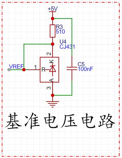
The key operating principle of the TL431 is as follows:
Comparator: The comparator inside the TL431 compares the voltage between its control terminal (Cathode) and anode (Anode) with an internal reference voltage (typically 2.495V). Feedback Mechanism: When the control terminal voltage is higher than 2.495V, the comparator turns on, lowering the output resistance of the TL431 and thus providing a larger current output. When the control terminal voltage is lower than 2.495V, the comparator turns off, increasing the output resistance and limiting the output current. Stabilized Output: By connecting the control terminal of the TL431 to its output terminal with an external resistor, the voltage at the control terminal can be adjusted, thereby adjusting the output voltage. The TL431 achieves a stable output voltage by adjusting its output current to maintain the control voltage at approximately 2.495V.

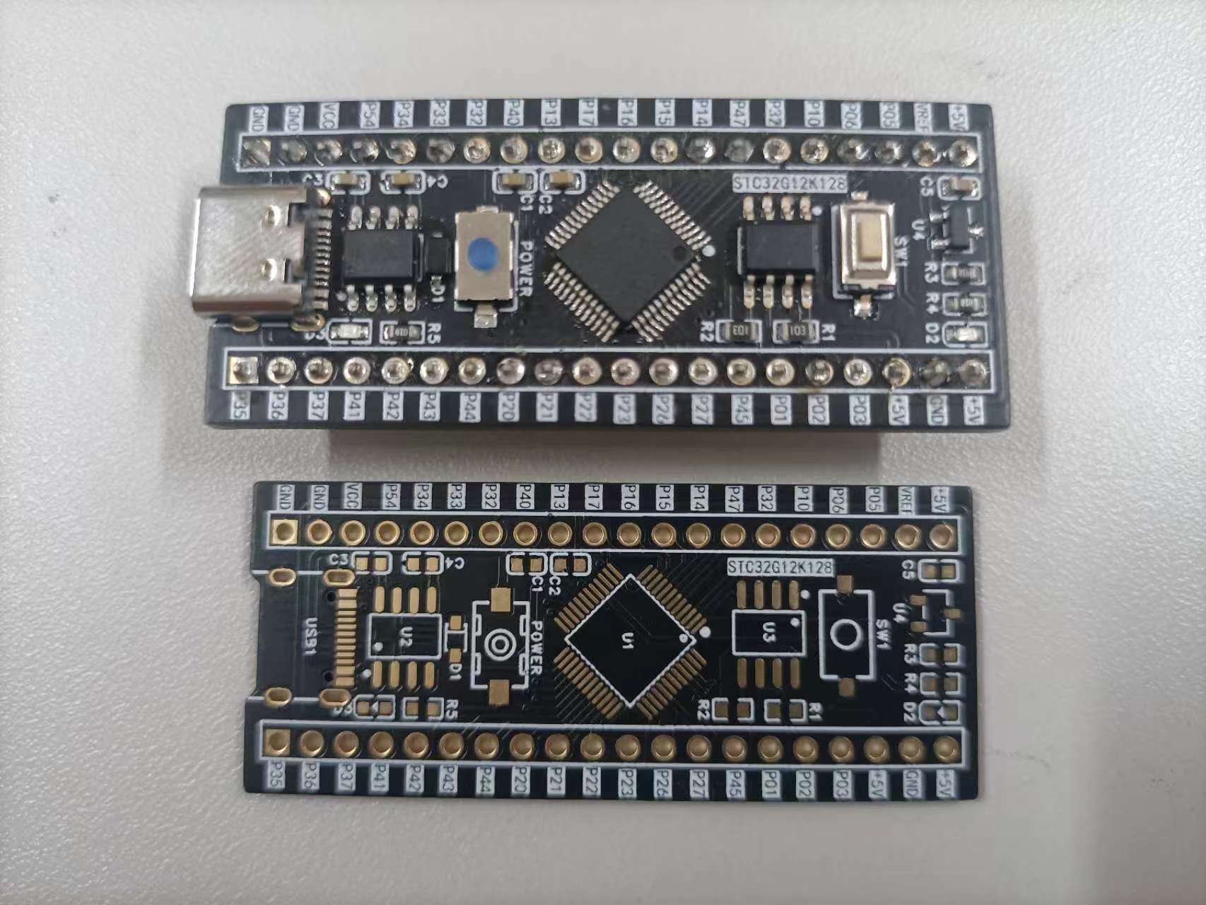
(PCB image
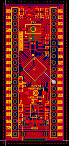
, 3D image,
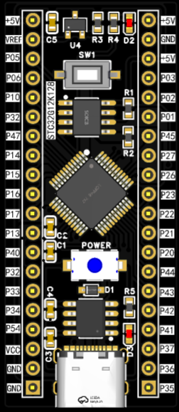
physical sample shown ) I also built an STC32G12K128 expansion board to verify if the core board's functions were implemented.

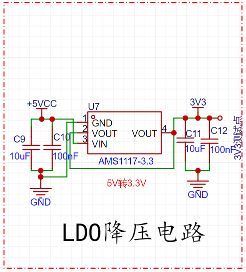
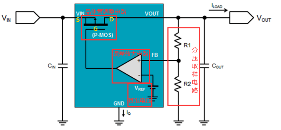
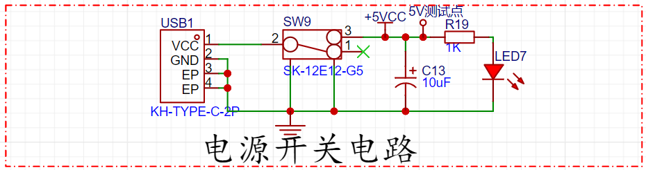
( Hardware circuit schematic design) The AMS117 LDO step-down circuit is a low-dropout linear regulator (LDO) with a fixed output voltage, providing a high-precision, stable output voltage. The AMS117 is based on a feedback regulation circuit using a reference voltage source and an error amplifier. It uses a differential amplifier to compare the output voltage with the reference voltage, adjusting the output voltage to maintain stability. An LDO typically consists of four main components: a voltage divider sampling circuit, a reference voltage, an error amplifier circuit, and a transistor adjustment circuit. Voltage divider sampling circuit: The output voltage is acquired through resistors R1 and R2; Reference voltage: Generated by a bandgap voltage reference to minimize the impact of temperature changes on the reference; Error amplifier circuit: The acquired voltage is input to the inverting input of the comparator and compared with the reference voltage (the desired output voltage) at the non-inverting input, and the comparison result is amplified; Transistor adjustment circuit: The amplified signal is output to the control electrode of the transistor (the gate of a PMOS transistor or the base of a PNP transistor), so that the amplified signal (current) can control the transistor's on-state voltage, which is a negative feedback adjustment loop. Power switch circuit: When the 2PIN-Type-C is plugged in, the switch is turned on, VBUS and +5V are conducted, and LED7 lights up for indication; when the switch is turned off, LED7 turns off. Buzzer circuit: 8-pin digital tube circuit PCB diagram, 3D diagram, physical diagram, software code design, button selection experiment, buzzer experiment, marquee experiment, interrupt experiment. Bilibili video link: JLCPCB & STC32G12K128 core board


STC32G12K128 interrupted LED flip.mp4
STC32G12K128 Minimum Core Board Video Demonstration.mp4
STC32G12K128 Minimum System Board Code Project.zip
PDF_STC32G12K128 Minimum Core Board + Expansion Board.zip
Altium_STC32G12K128 minimum core board + expansion board.zip
PADS_STC32G12K128 Minimum Core Board + Expansion Board.zip
BOM_STC32G12K128 Minimum Core Board + Expansion Board.xlsx
93475
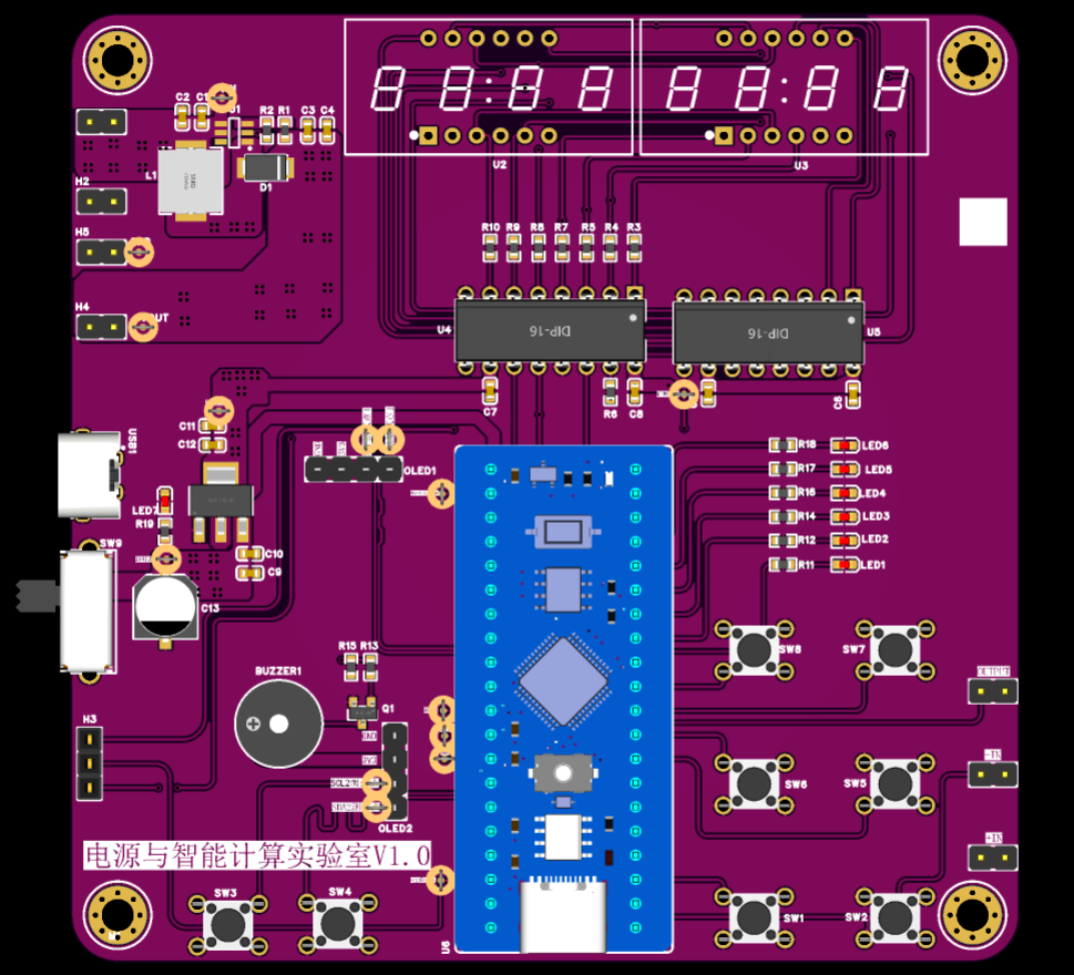
48-Pin Touch Button Experimental Board @STC8H4K64TL
Touch button experimental board @STC8H4K64TL-LQFP48
80mA high current digital tube automatic refresh display @STC8H4K64TL
14 touch buttons, four digital tube displays
The touch button experimental board verifies
the main functional features
: 14 touch buttons for input and interaction, which can control other hardware components, such as LED digital tubes.
An 80mA high-current digital tube automatic refresh display (@STC8H4K64TL)
can drive and automatically refresh the display, greatly reducing the CPU load and simplifying program design.
Two 4-digit common-cathode digital tubes and two 4-digit common-anode digital tubes
support 80mA high current, ensuring stable operation of the digital tubes under high brightness.
14 indicator lights, corresponding one-to-one with the 14 touch buttons,
are used to display the status of the touch buttons, enhancing the user interaction experience.
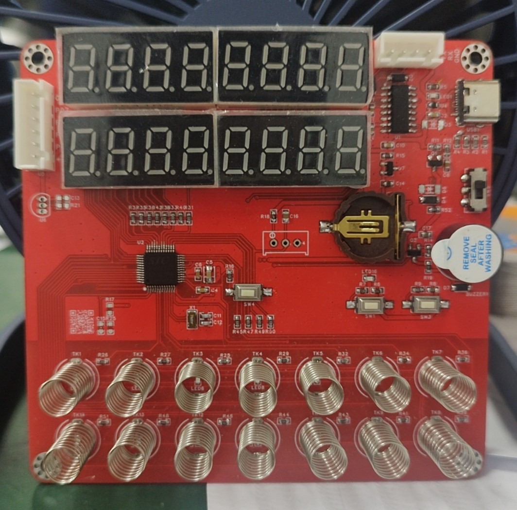
The TC8H4K64TL-LQFP48 experimental board is a feature-rich development board integrating 14 touch buttons, two 4-digit common-cathode digital tubes, two 4-digit common-anode digital tubes, and 14 touch button indicator lights. Its unique 80mA high-current digital tube automatic refresh function makes the digital tube display more stable and efficient. This configuration is suitable for applications requiring high-precision control and display, such as electronic musical instruments and measuring instruments.
[New Reminder] LCSC has open-sourced its Touch Button Experiment Board @STC8H4K64TL-LQFP48 - MCU Creative Design Competition @ [STC & LCSC EDA] National Chip Technology Exchange Website - STC Global 32-Person 8051 Enthusiast Mutual Aid and Exchange Community (stcaimcu.com).
Welcome everyone to join the discussion.
PDF_48-Pin Touch Button Experimental Board @STC8H4K64TL.zip
Altium_48-Pin Touch Button Experimental Board @STC8H4K64TL.zip
PADS_48-Pin Touch Button Experimental Board @STC8H4K64TL.zip
BOM_48-Pin Touch Button Experimental Board @STC8H4K64TL.xlsx
93479
electronic

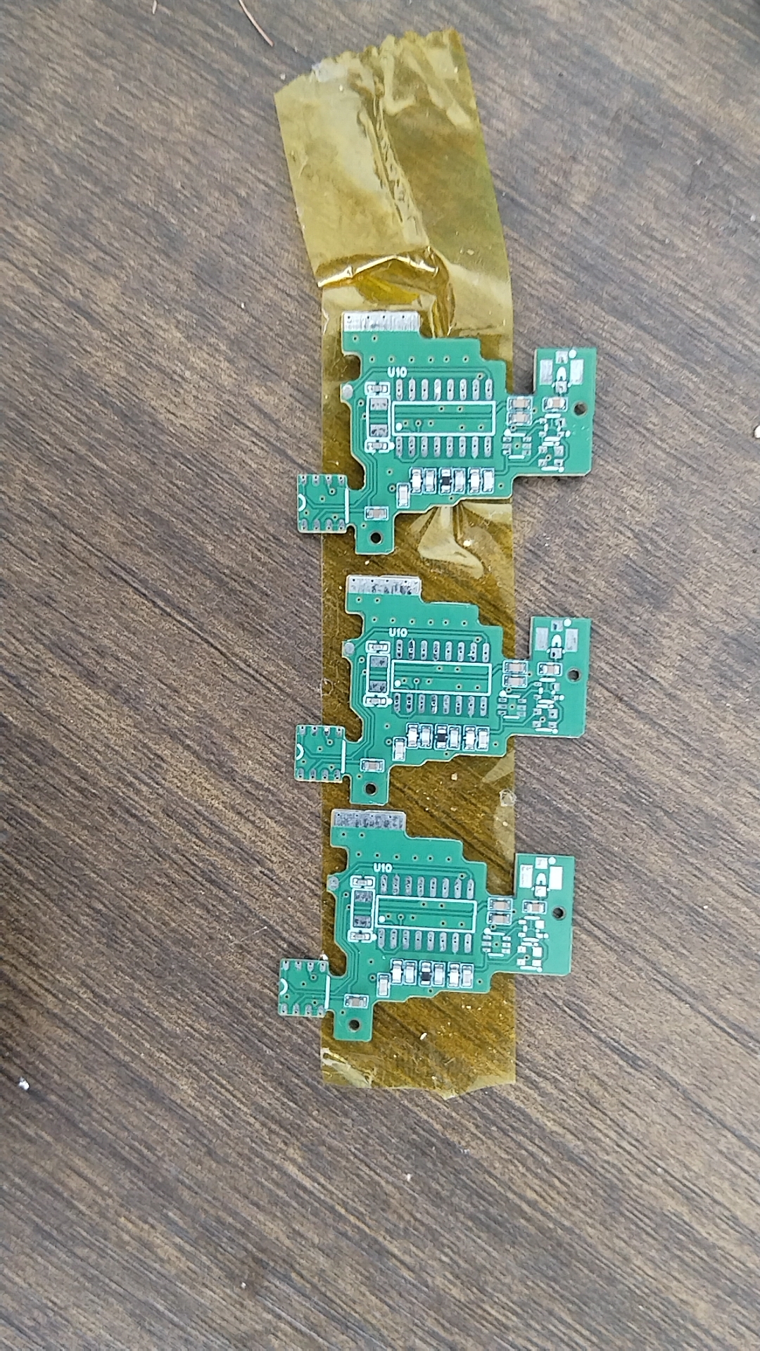

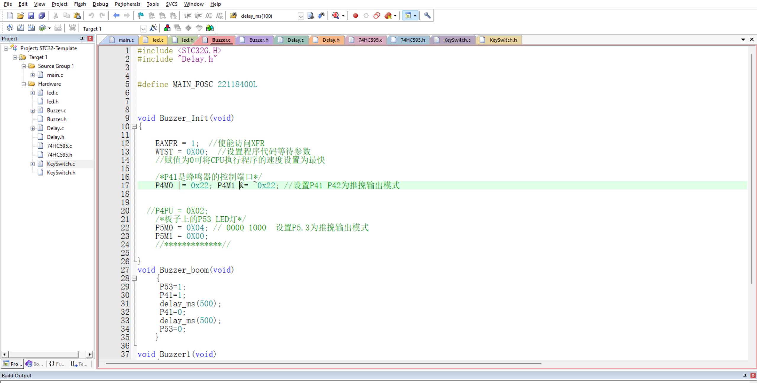
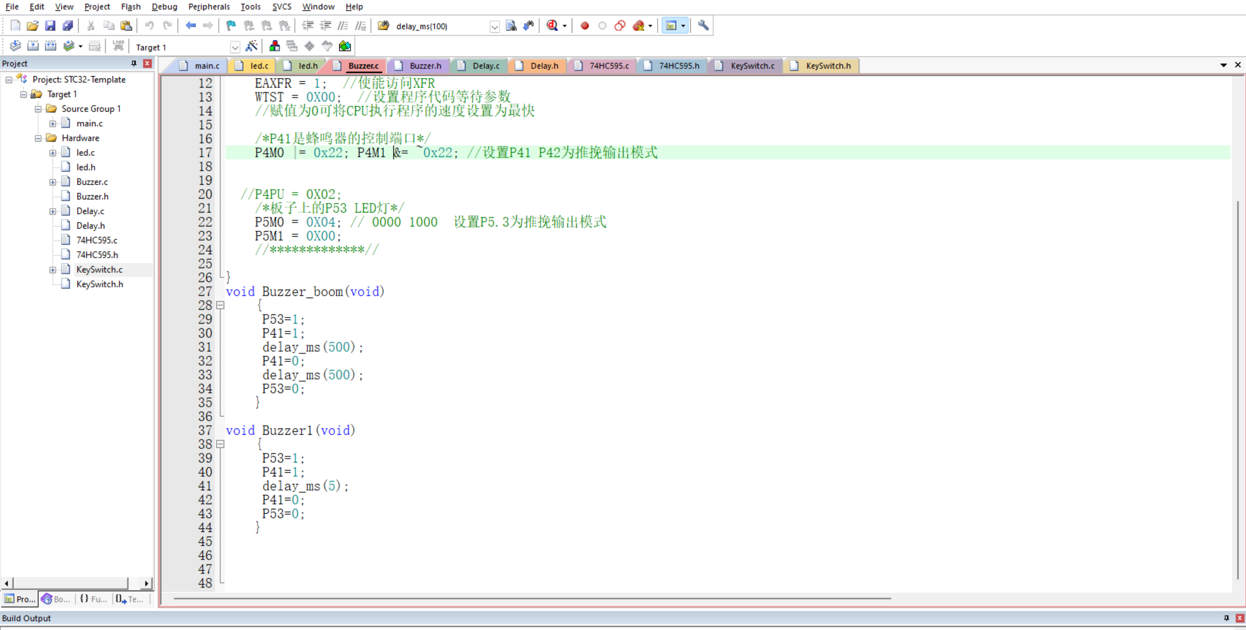
 III. Firmware Flashing and Log Debugging.
  Click to jump to the online serial port debugging tool
 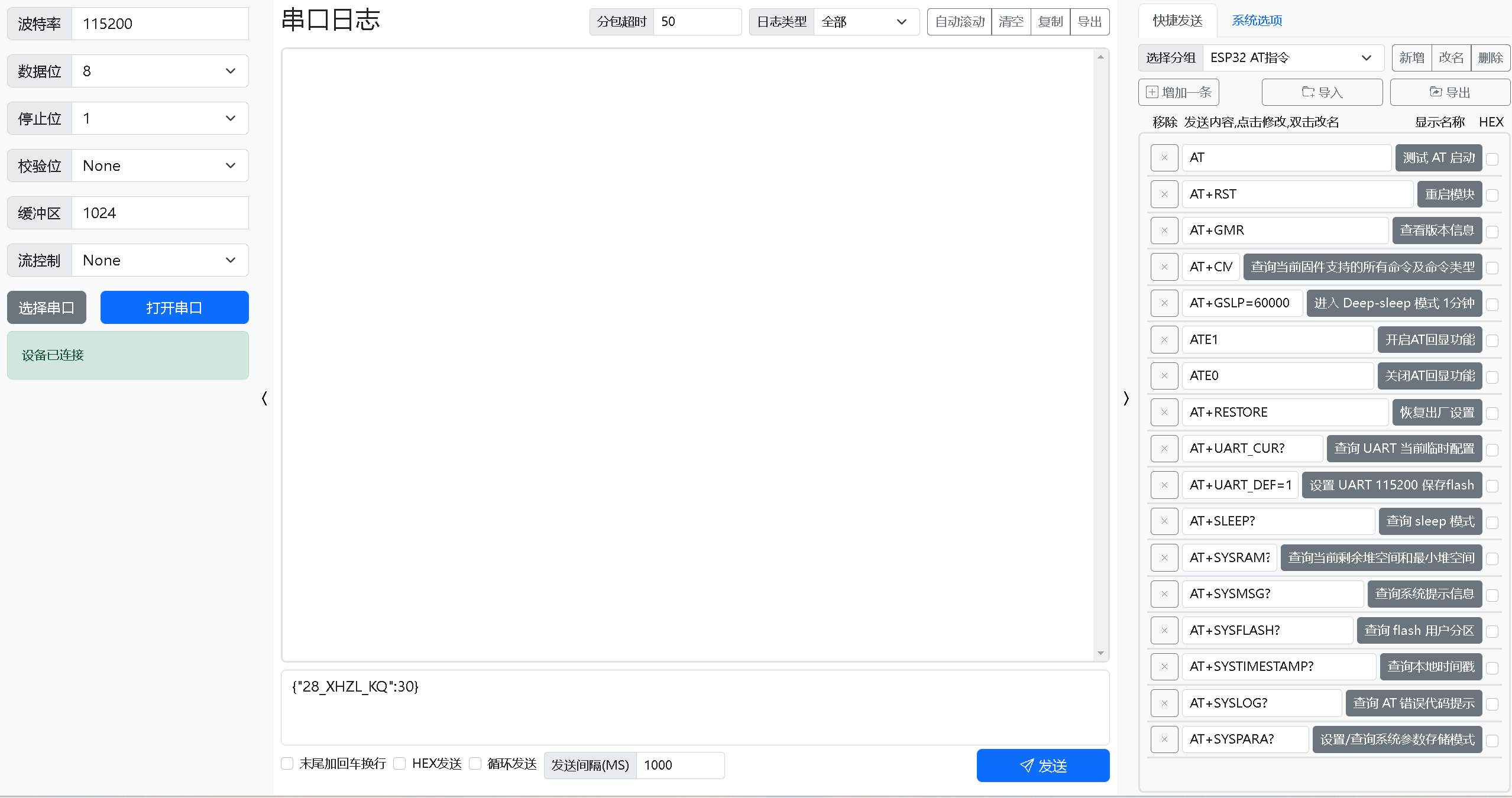 TIPS: To switch from KEY4 to other functions, press and hold the corresponding button for 5 seconds.
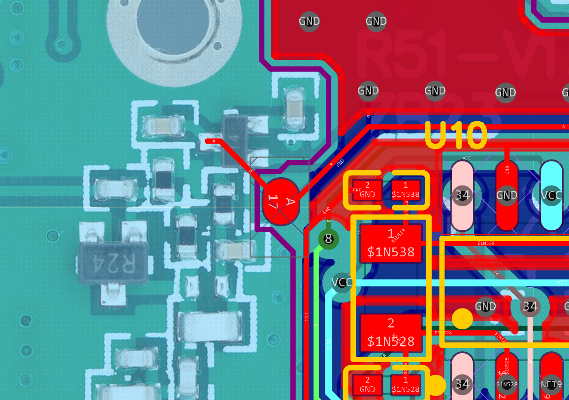
 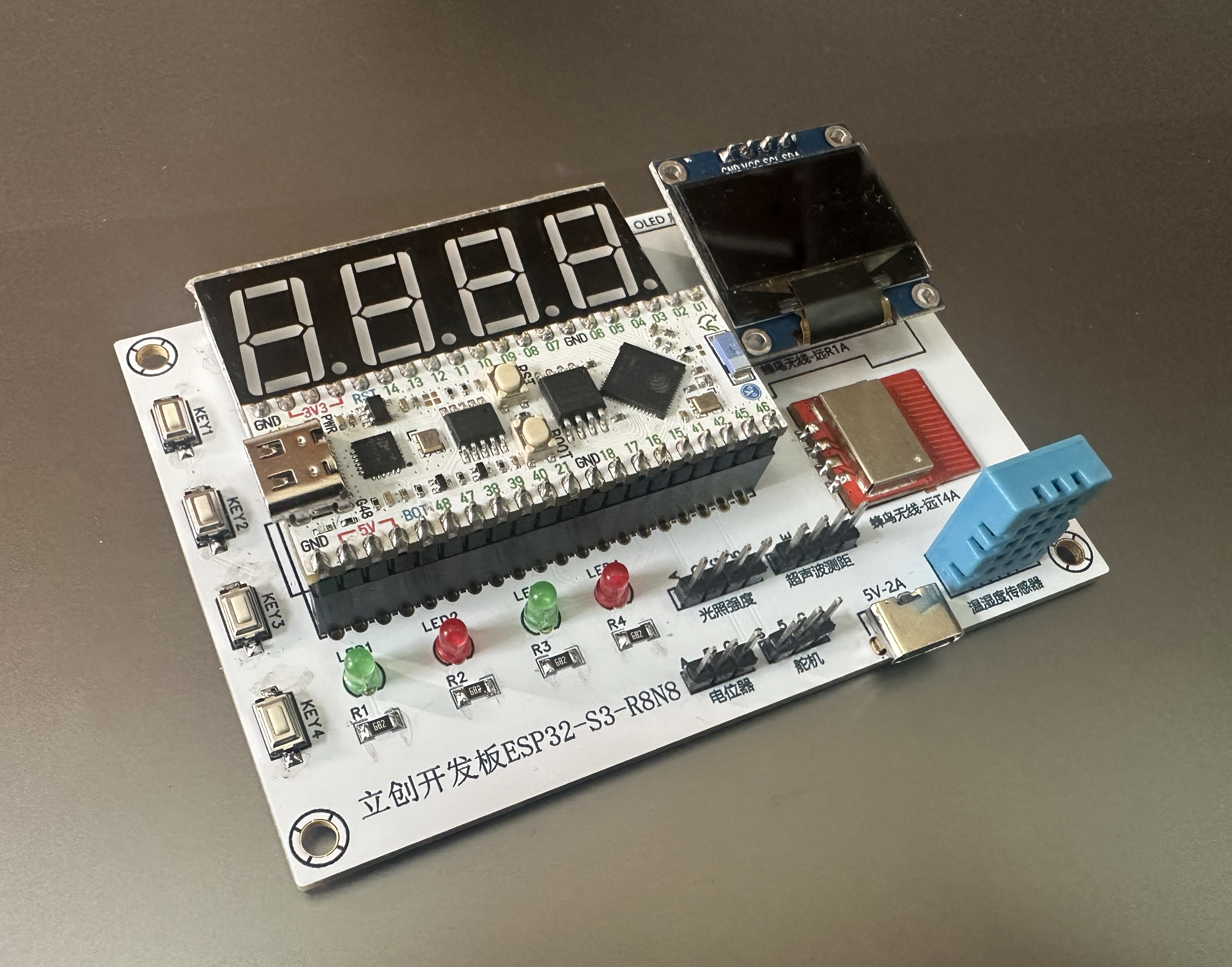 front. Simulation diagram
 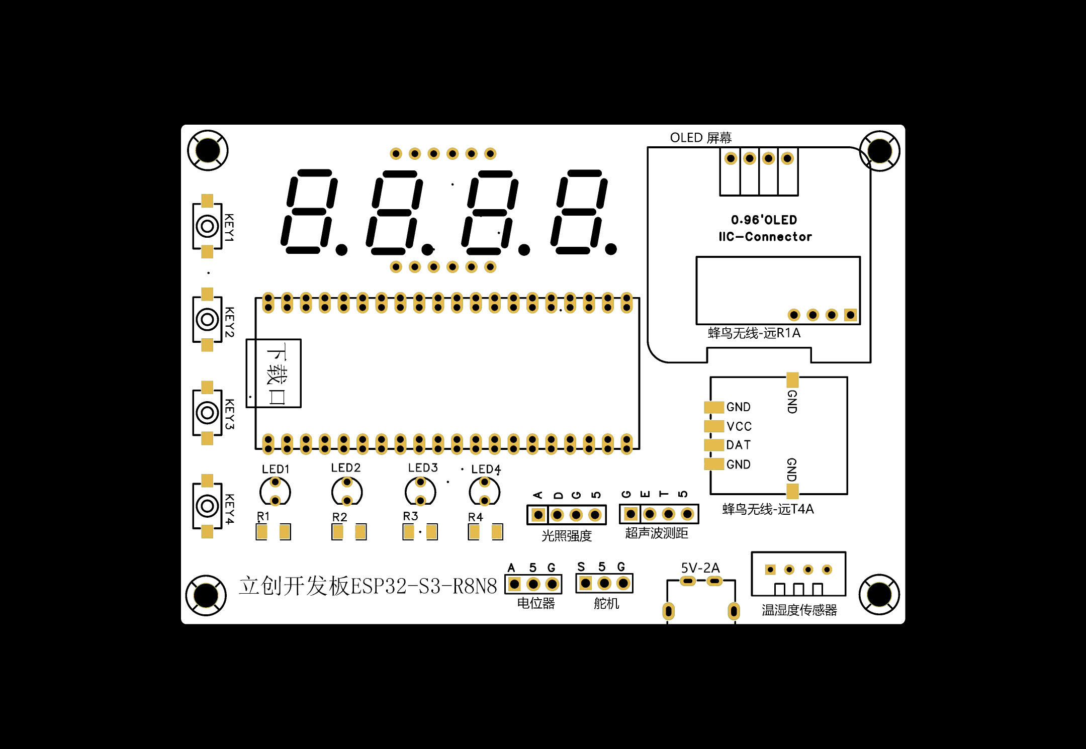 (back side)
  Fifth, Bluetooth communication via mobile APP.
 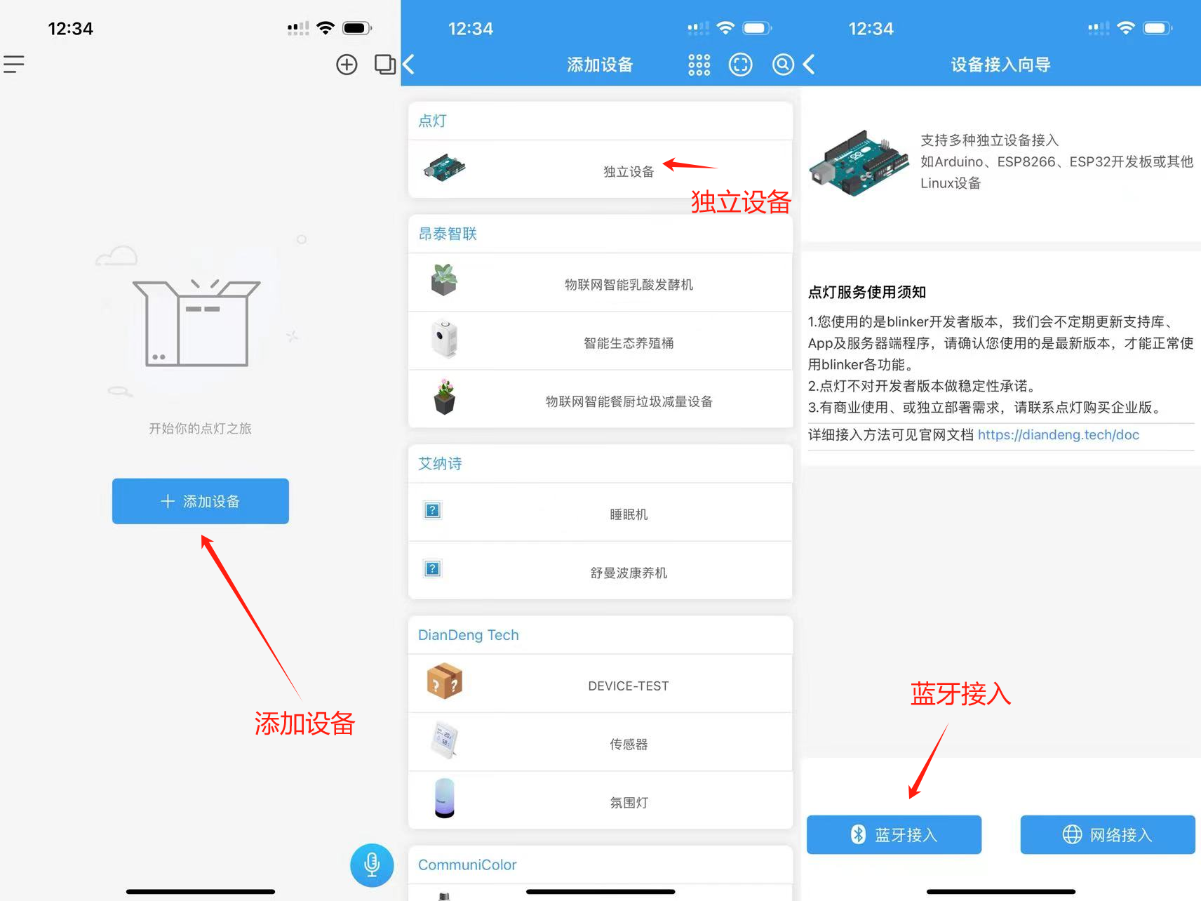 Step 2: Bind development board
  ; Step 3: Update interface configuration
  . Done!
  VI. User Service Agreement
  Firmware Version Update Log (Under continuous development)
 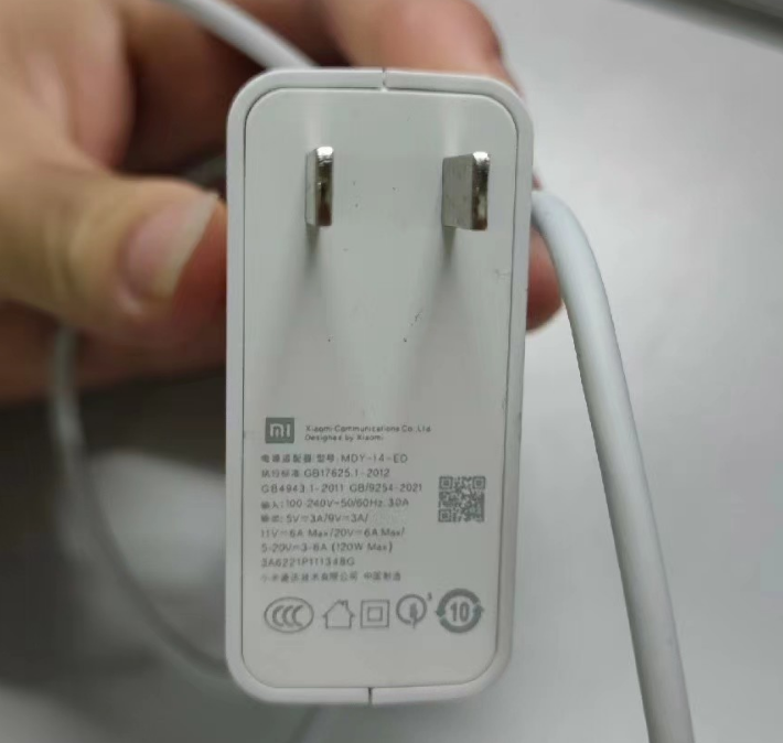 II. Charger Architecture
 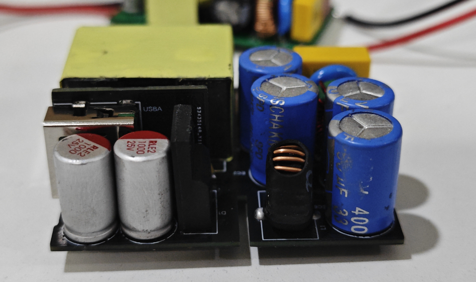 III. Components


 京公网安备 11010802033920号

 ST62T20B6/SWD


