I. Project Name:
- Smart Car Design Based on LCSC Liangshan School
- Hardware design is described below, and software design code has been uploaded to Attachment
II. Objectives:
- Design a Bluetooth-controlled car with line-following and obstacle avoidance functions, and to give the car expressions and status displays.
- Originally, I also wanted to use a radar monitoring sensor to track human movement, but due to module limitations, I was unable to use it.
III. Function Introduction:
- This project uses Bluetooth remote control to move the car in direction. It can also switch to line-following mode, obstacle avoidance mode, etc. via Bluetooth.
IV. Project Description
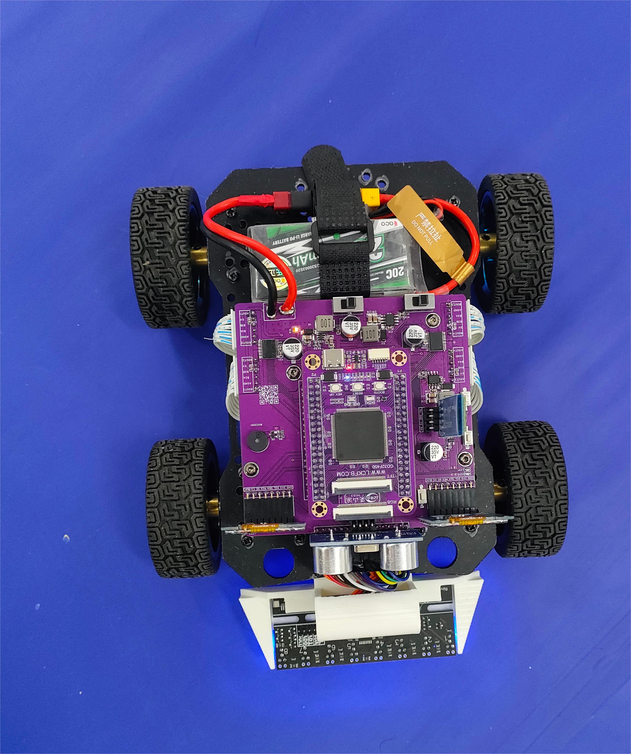
Hardware used in the project:
- LCSC Liangshanpai
- Mainboard of the car (integrating voltage regulator module and TB6612 motor driver)
- Bluetooth module
- Ultrasonic module
- Ganwei eight-channel grayscale sensor module
- Buzzer
- LEDs (SMD + DIP)
- Four DC geared motors (Lunqu Technology MG513 DC geared motor with Hall sensor)
- Two 240*280 TFT LCD screens
V. Hardware Design
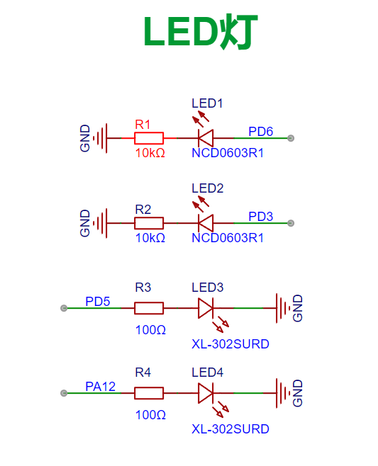
1. LED lights
![image.png]
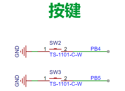
2. Buttons
![image.png]
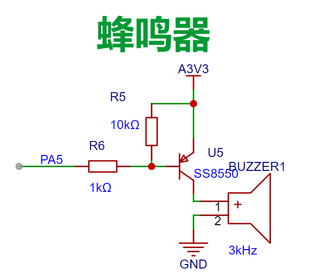
3. Buzzer
![image.png]
4. Line-following module interface
![image.png]
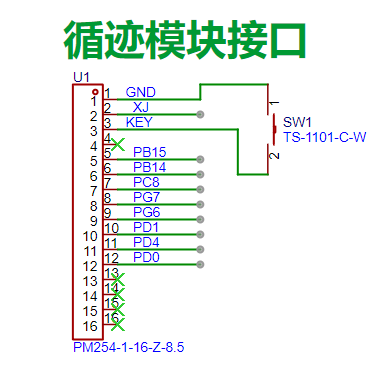
Here XJ is 5V. The button design is based on the design requirements given by Ganwei Technology.
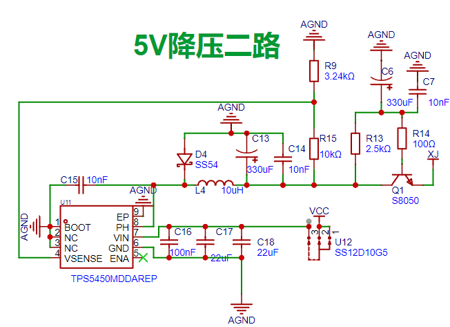
5.

DC-DC 5V Step-Down Circuit Both circuits use 5V step -down technology
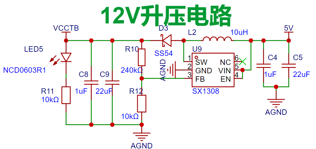
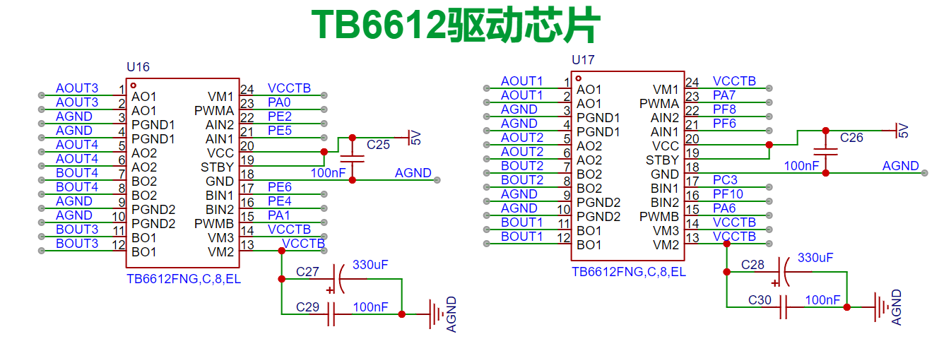
. A single 5V circuit powers the eight grayscale sensors. Ensure the 5V power supply to the sensors is stable. Do not share a 5V power supply with inductive loads such as servos, motors, or horns. Inductive loads generate very high voltages when current changes abruptly, which can easily burn out the sensors. The voltage divider resistors in the circuit need to be adjusted according to the actual situation. 6. DC-DC 12V Boost Circuit This circuit uses the SX1308 boost chip. The voltage divider resistors in the circuit need to be adjusted according to the actual situation. 7. LDO 3V3 voltage regulator circuit ![image.png] 8. TB6612 driver circuit ![image.png] 9. Motor interface circuit ![image.png] ![IMG20240720155028.jpg] ![IMG20240720155036.jpg] ![WeChat image_20240721085657(1).jpg] VI. Skills Mastery: - Through this project, I learned some code logic control. - I learned how to display desired information on an LCD. - I learned and mastered DC-DC buck-boost circuits. - Shortcomings - I could not use the SDIO on the Liangshanpai platform to read data and then display the data information in the SD card on the LCD. Finally, I got stuck on reading the information from the SD card, and the read data was displayed as a garbled screen on the LCD. VII. Problems Encountered and Solutions - For PWM Output: - Testing revealed that only port A could output a PWM signal to drive the motor; other pins could not. The reason for this was unknown. The hardware pins were then modified, and all were changed to port A. - For Bluetooth Control of the Car's Movement: - In the initial design phase, Bluetooth data transmission caused the car to enter line-following mode. Two situations occurred: first, the car only executed one line-following function; second, it could not exit line-following mode. Through web searches and AI queries, combined with the provided code, the logic was modified, and the desired result was achieved. - For Initialization of the Two LCDs: - Modifying the macro definitions failed to achieve the desired functionality and resulted in errors. The macro definitions had to be discarded, and modifications were made directly to the .c file.


 京公网安备 11010802033920号

 UPD42S16160LLE-A80


