1. Project Name:
Smart Car Design Based on LCSC Liangshan School
2. Objectives:
To become familiar with the development process of embedded systems projects and master the ability to design a smart car hardware circuit, software programming, and system debugging.
3. Functional Introduction:
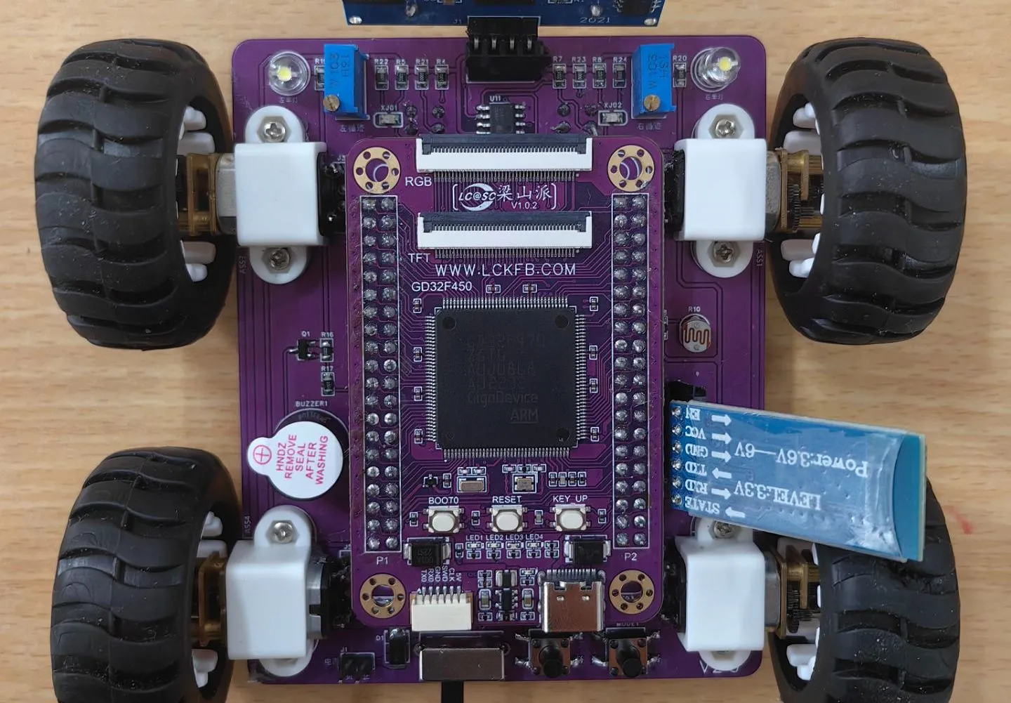
The smart car is equipped with two LED lights at the front, one on each side, which can be used to simulate the headlight status of a vehicle passing by; the smart car has two independent buttons, KEYS and KEYM, which can be used for starting and switching between motion modes; the smart car is equipped with a buzzer, which can be used to sound an alarm when encountering obstacles, and can also play music by changing its output frequency using a timer; the smart car is equipped with four motor drivers and four N20 motors, enabling PWM output and speed control; the smart car is equipped with two infrared tracking channels, which can be used to follow black lines, and the use of comparator circuits can be learned to implement the tracking function; the smart car is equipped with an HCSR04 ultrasonic module interface circuit, which can be used to implement ultrasonic obstacle avoidance function by learning the module principle and underlying driver code; the smart car provides an HC-05 Bluetooth module interface circuit, which can be used with a mobile phone Bluetooth APP to realize the function of wirelessly controlling the car.
4. Skills Acquisition
: Develop the ability to analyze embedded circuits and understand schematic diagrams; acquire basic skills in component selection and datasheet reading; learn the working principles of a smart car and basic methods of embedded circuit design; develop schematic and PCB design skills, cultivating independent project design thinking; understand the basic functions of GD32 and the use of peripherals, and get started with GD32 project development; understand the ADC acquisition principle and implement voltage acquisition; understand the PWM principle and implement PWM control of different duty cycles; understand serial communication and Bluetooth data transmission principles to implement mobile phone control functions; master the acquisition and control methods of infrared and ultrasonic sensor data.
5. Problems Encountered and Solutions:
The biggest concern in the entire project was how to implement mobile phone control via Bluetooth, but the actual problems encountered were not this. When soldering the motors to the car, only three of the soldered motors turned; the other one wouldn't turn no matter what. After testing with a multimeter for a long time, no problem could be found. At one point, it was suspected that the motor was broken. It turned out that the pins of the driver chip were not soldered properly. A problem was also encountered when using ultrasonic ranging. Although ultrasonic waves can detect obstacles ahead, their reaction time is too long. Before the system can react, it crashes into the obstacle. The solution was to slow down the vehicle and increase the obstacle detection distance, but the actual effect was still not very good.
6. Overall Design Scheme:
The power supply circuit uses two 7.4V lithium batteries to power the system, which is then stepped down to 5V by a step-down chip to power the microcontroller system. The LCSC Liangshanpai core board is connected to the LED lights, button circuit, obstacle avoidance circuit, tracking circuit, ADC voltage acquisition circuit, Bluetooth remote control circuit (wireless remote control function), buzzer, and motor drive circuit on the intelligent car expansion board.
7. Recommendations for Project Consumables:
For some resistors and LED lights, I directly used those from the school's laboratory. Most other consumables can be purchased directly from the LCSC online store. Pre-packaged 7.4V lithium batteries and N20 motors can also be purchased directly from Taobao. It is recommended to buy motor covers when purchasing motors. Driver chips on the LCSC online store require a minimum order of 100, so it is recommended to purchase them from Taobao.
8. Overall Learning Experience
The entire learning process took about two months, mainly due to school commitments, allowing me to study only in my spare time. In the early stages of the project, the theoretical circuit design, component selection, and datasheet reading were somewhat overwhelming for a first-year student. However, when I actually started soldering, debugging, and programming, the gap between theory and practice became apparent. For example, a theoretical circuit diagram might not work properly in actual soldering due to a small faulty solder joint, which was quite frustrating.
Problems encountered in the project, such as a motor not turning and excessively long ultrasonic response time, while frustrating at times, became valuable learning and growth experiences. I learned how to use a multimeter for circuit troubleshooting.
In terms of software programming, I learned to use the GD32 microcontroller from scratch, mastering key technologies such as ADC acquisition, PWM control, and serial communication. This not only enhanced my programming skills but also gave me a more comprehensive understanding of the hardware and software integration of embedded systems. Especially noteworthy was the implementation of controlling a car via Bluetooth using a mobile phone.
From initially just completing a semester project to finally achieving concrete results, overall, the gains were substantial.
9. Principles of Some Main Functions:
Tracking Circuit.
The tracking circuit utilizes the principle that infrared light reflects differently when encountering ground of different colors. It employs an LM393 voltage comparator and an ITR9909 infrared diode pair, with the ITR9909 integrating both the infrared emitter and receiver. The tracking circuit works by connecting pin 1 of the voltage comparator to a microcontroller pin, configuring the I/O to input mode. When pin 1 of the voltage comparator outputs a high level, it indicates that the infrared light is absorbed, a black line is detected, LED6 lights up, and the microcontroller I/O reads the high level.
Ultrasonic
Ranging: The ultrasonic ranging principle involves an ultrasonic transmitter emitting ultrasonic waves and starting a timer simultaneously. The ultrasonic waves propagate through the air; when they encounter an obstacle, they send a signal back to the ultrasonic receiver. Upon receiving the signal, the receiver immediately stops the timer, resulting in a time interval t. Since the speed of ultrasound in air is 340 m/s, the distance to be measured can be calculated using the formula s = 340 x t / 200. The principle of
infrared tracking
detection is that an infrared emitter emits light onto the ground. When the infrared light encounters a white surface, it is reflected, and the infrared receiver receives the reflected light. After passing through a voltage comparator, it outputs a low level. When the infrared light encounters a black surface, it is absorbed, and the infrared receiver does not receive the reflected light. After passing through a voltage comparator, it outputs a high level.
10. The demonstration video
was filmed at the school and may not be very clear. The original video is attached.


 京公网安备 11010802033920号

 160564J250M-F


