1. Project Introduction: This project
utilizes a Sensirion temperature and humidity sensor + STM32G030K6T6 to achieve real-time temperature and humidity data acquisition.
Thanks to JLCPCB for providing the free training camp!
Thanks to Sensirion for their excellent temperature and humidity sensor!
Thumbs up!
*2. Project Attributes:
The overall project difficulty is not high. JLCPCB engineers guided everyone from scratch, step-by-step through the entire project, making it very suitable for beginners. Even I, an electronics novice, could complete it; believe me, you can too.
3. Open source license
GPL3.0
4. Hardware part
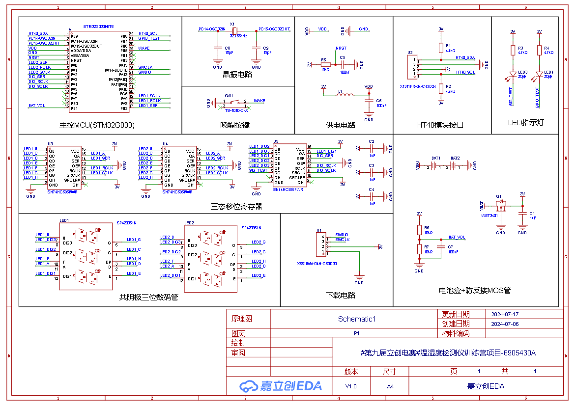
(1) Circuit schematic diagram
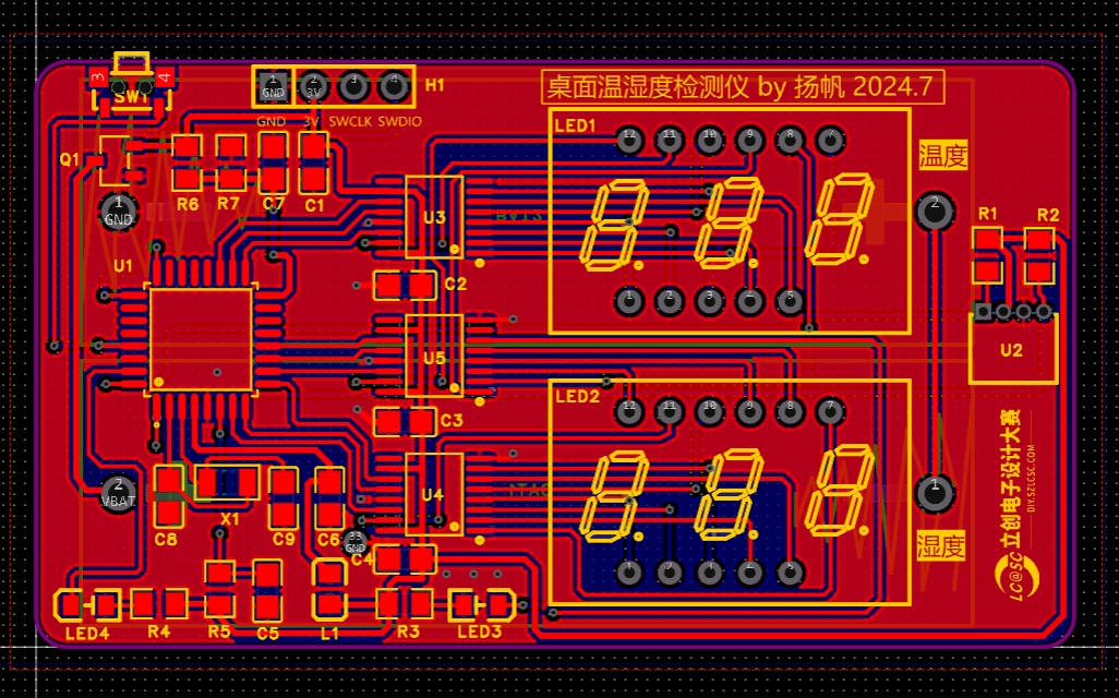
(2) PCB wiring diagram
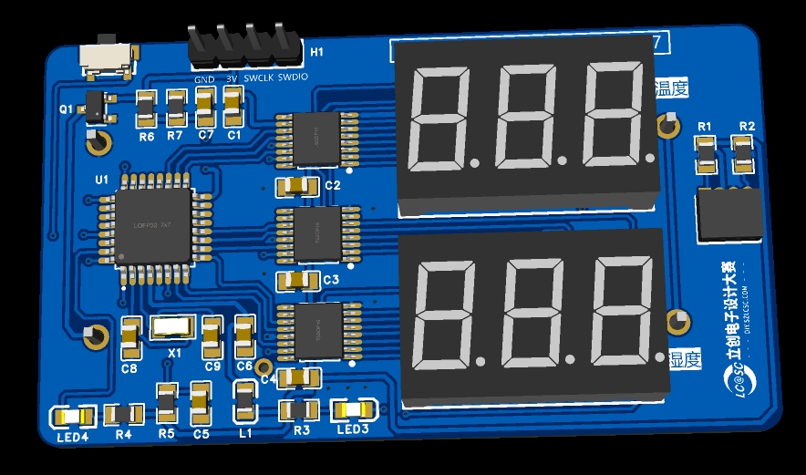
(3) 3D model diagram
(4) Sensory temperature and humidity sensor module
The desktop temperature and humidity meter uses the Sensory SHT40 temperature and humidity sensor module to detect temperature and humidity.
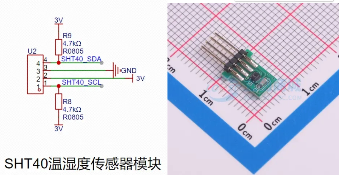
The SHT40 uses IIC for communication. According to the SHT40 datasheet, 0x44 is the IIC address; when the least significant bit of the address is 0, it means reading data, and when the least significant bit is 1, it means writing data; when the 0xFD instruction is sent, it means high-precision measurement of temperature and humidity;


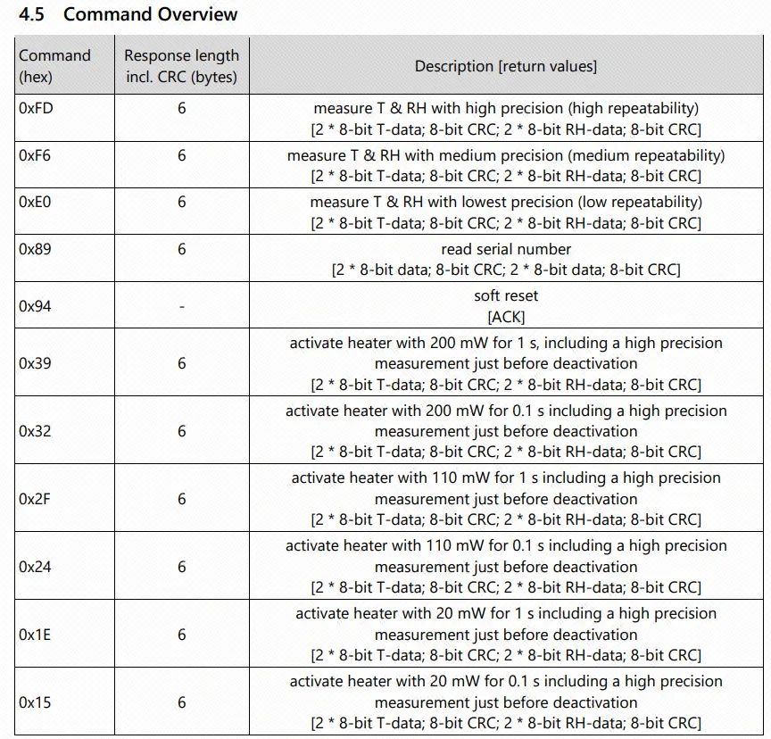
the temperature and humidity can be obtained by formula calculation of the data;

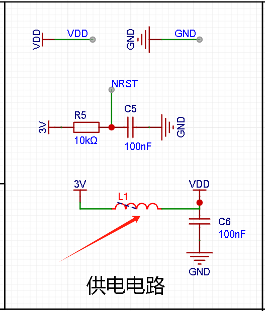
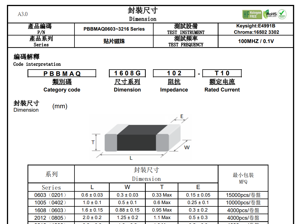
(5) Ferrite
bead Ferrite beads play an important role in anti-interference. It is mainly used to suppress high-frequency signals and eliminate RF noise in the transmission line structure, thereby reducing electromagnetic interference (EMI). Ferrite beads allow DC signals to pass through, but can effectively filter out AC signals, especially RF energy. In addition, ferrite beads also have the ability to absorb electrostatic pulses, which helps to protect the circuit from accidental electrical shocks. Therefore, a surface-mount ferrite bead produced by Spectro is added to the power supply section to protect the circuit.
5. The software
is attached. The software is divided into two versions: one is the always-on version, which is used for debugging; the other is the low-power mode, which can be used in actual use scenarios. After pressing the button, the temperature and humidity will be displayed alternately several times, and then it will enter sleep mode to reduce power consumption.
(1) Digital tube + tri-state shift register
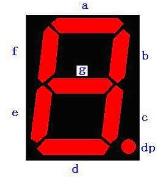
Digital tube is a semiconductor light-emitting device. Its basic unit is light-emitting diode, also known as LED digital tube. Digital tubes can be divided into seven-segment digital tubes and eight-segment digital tubes according to the number of segments. The eight-segment digital tube has one more light-emitting diode unit than the seven-segment digital tube, which is the extra decimal point (DP). This decimal point can more accurately represent the content that the digital tube wants to display, as shown in the figure:
According to the number of light-emitting diodes (8), it can be divided into 1-digit, 2-digit, 3-digit, 4-digit, 5-digit, 6-digit, 7-digit digital tubes.

According to the connection method, it can be divided into common anode digital tubes and common cathode digital tubes.
A common-anode seven-segment display refers to a seven-segment display where the anodes of all LEDs are connected together to form a common anode (COM). In application, the common terminal COM should be connected to +5V. When the cathode of a segment's LED is at a low level, the corresponding segment lights up; when the cathode of a segment is at a high level, the corresponding segment is off.
A common-cathode seven-segment display refers to a seven-segment display where the cathodes of all LEDs are connected together to form a common cathode (COM). In application, the common terminal COM should be connected to ground (GND). When the anode of a segment's LED is at a high level, the corresponding segment lights up; when the anode of a segment is at a low level, the corresponding segment is off.

Seven-segment displays operate in two modes: static display and dynamic display.
The characteristic of static display is that each segment selection of a seven-segment display must be connected to an 8-bit data line to maintain the displayed character code. Once a character code is input, the displayed character can be maintained until a new character code is input. The advantage of this method is that it consumes less CPU time and the display is easy to monitor and control. The disadvantage is that the hardware circuit is more complex and the cost is higher. For example, if four static seven-segment tubes are used, then 32 I/O pins are needed for control.
The characteristic of dynamic display is that the segment selection lines of all seven-segment tubes are connected in parallel, and the digit selection lines control which digit is active. Dynamic scanning display is used to select the illuminated seven-segment tubes. Dynamic scanning display means that the character code and corresponding digit selection are sent to each seven-segment tube in turn, utilizing the afterglow of the LEDs and the persistence of vision to make it appear as if all seven seven-segment tubes are displaying simultaneously. The brightness of dynamic display is slightly lower than that of static display, so the current-limiting resistor should be slightly smaller than that used in static display circuits.
This system uses two common-cathode 3-digit LED displays to show temperature and humidity data. Considering the number of pins, three shift registers (SN74HC595PWR) are added to drive the common-cathode LED displays. Common- cathode


segment codes:
Segment Code Character Segment Code Character Segment Code Character Segment Code Character 0x3f 0 0x6d 5 0x77 A 0x71 F 0x06 1 0x7d 6 0x7c B 0x00 No display 0x5b 2 0x07 7 0x39 C 0x4f 3 0x7f 8 0x5e D 0x66 4 0x6f 9 0x79 E The SN74HC595 driver timing is relatively simple. First, a high or low level is input to the SER pin, and then a rising edge of SCLK is generated to send the data out. Here it is an 8-bit data shift register, so it loops 8 times. The last rising edge of RCLK latches the data and keeps it unchanged until the next transmission. Here we simulate the transmission timing. First, the data to be sent is 0xFE (1111 1110). At this time, the highest bit is sent first, that is, 0xFE & 0x80, to judge the high and low levels. Then the data is sent to QA. Then continue, send the second highest bit, that is, (0xFE and so on... (2) I2C IIC is a two-wire bidirectional synchronous serial bus protocol. Bidirectional means that both parties can send and receive data. Synchronous means that both parties have the same clock pulse (SCL line). In IIC, the device is divided into master device and slave device. Generally speaking, whoever controls the clock line is the master device.

IIC devices all have a device address, which is used to identify multiple devices when they communicate.
IIC is half-duplex communication, which only supports one-way communication (only one data line) at the same time.
The IIC pin of the microcontroller is usually set to open-drain output, and the high level is output through an external pull-up resistor. The advantage of doing this is to prevent signal confusion when multiple devices communicate.
The entire IIC communication process mainly includes the following processes:
host start timing;
host send address timing;
host wait for slave response timing;
host send read/write data timing;
host wait for slave response timing;
stop timing;
(3) voltage acquisition
(4) Sensirui temperature and humidity sensor module
6. After
the first time doing teppanyaki surface mount, the first time using STM32CubeMX, the first time using I2C, and the first time using Sensirui temperature and humidity sensor, the process of struggling was painful but happy, but the result was beautiful. Isn't the meaning of life to constantly challenge and break through oneself?
(1) The first time I tried to solder surface mount devices, I used a thick needle to place too much solder paste, which caused very serious solder bridging. Afterwards, each solder joint only needs a small amount of solder paste. When soldering components on a hot plate, you must first solder those with many pins and those that are not easy to solder. Capacitors, resistors, and LEDs should be placed later, as they are easier to handle.
(2) Solder bridging method: Apply an appropriate amount of flux and then use a knife tip to flick it out; use a desoldering wick to remove excess solder while heating; add a little solder and use a soldering iron to drag it out to remove excess solder paste. Related tutorial: https://www.bilibili.com/video/BV1Xa411u7mg
(3) When downloading the program, there is a problem that the downloader can be recognized but communication is not possible. The error message is: SWD/JTAG Communication Failure. Upon inspection, it was found that VDD and 3V networks were not connected, which prevented the MCU from being powered. After connecting the L1 to R3 jumper wire, the download was normal.


(4) The STM32CubeMX programming method is very simple and labor-saving, and is friendly to beginners. You can use it more often. You can write programs by dragging and dropping. It's so much better not to have to remember so many headache-inducing things.
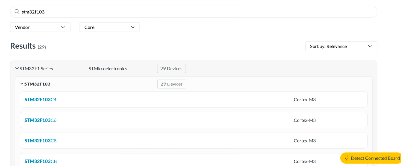
(5) Installing the corresponding MCU software package in Keil is very slow. You can download it yourself and install it manually. The download address is https://www.keil.arm.com/devices/. First, search for the corresponding model, such as STM32F103C8.
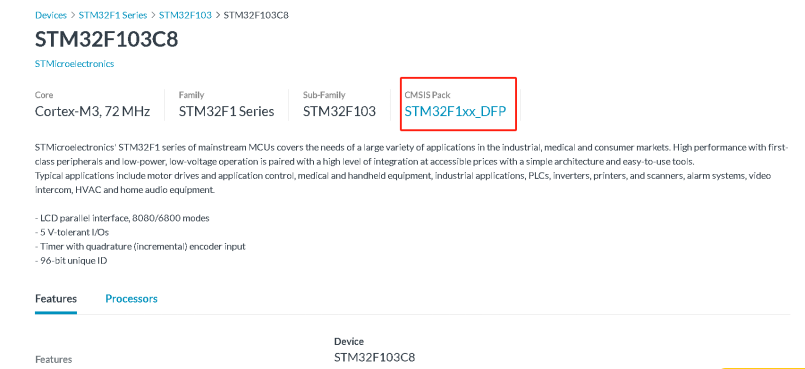
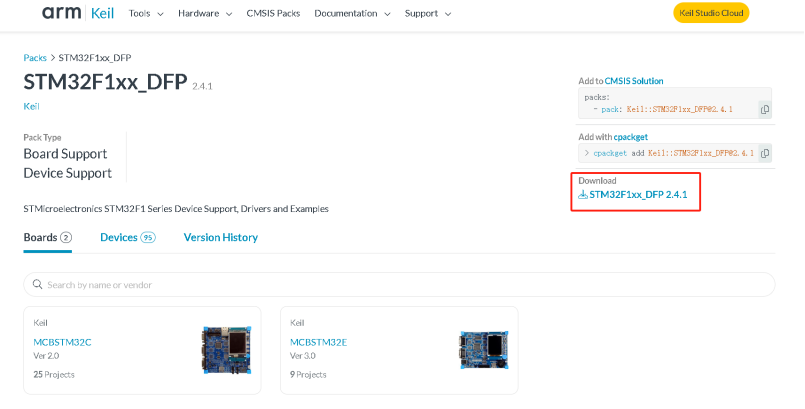
After searching, click on the corresponding MCU connection to enter the details page. Click on the content in the red box to enter the download interface.
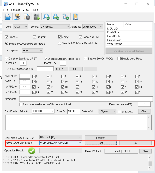
(6) When using the Qinheng downloader, you need to open the Qinheng downloader tool WCH-LinkUtility.exe, switch the mode to WCH-LinkDAP-WVINUSB, first click "get" to get the list of supported modes, and then select WCH-LinkDAP-WVINUSB and click "set". After setting, remember to close WCH-LinkUtility.exe to prevent the downloader from occupying the Keil connection and causing it to fail.
How to use it in Keil:
Open the magic wand (Options for Target).

Click Debug and select to use CMSIS-DAP Debugger.
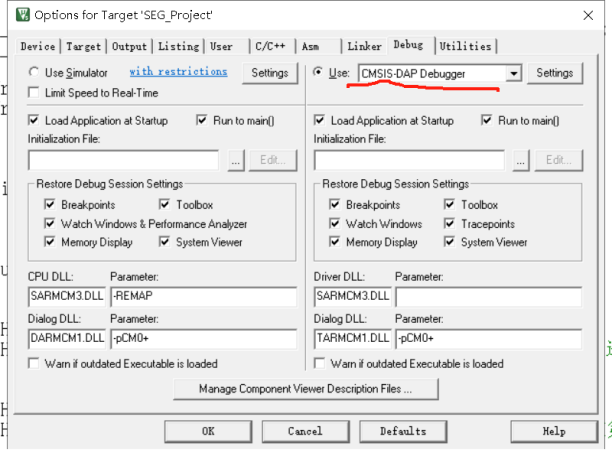
Click Settings. If the serial number can be recognized on the left and the SW device can be recognized on the right, it can be used normally.

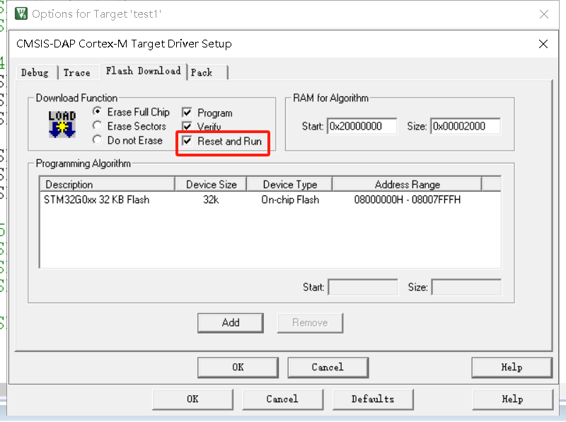
Select “Reset and Run” to download the program and it will run automatically again. Otherwise, you need to manually turn off the power and then turn it on again.
(7) The LED was not soldered properly, resulting in one of them being reversed. The circuit was not connected and the program could not be executed normally after writing it. After modification, the LED was lit successfully.

(8) Handling the problem of abnormal display of digital tube: There are three 595s. The first one was not properly soldered. When testing the program, the problem was encountered:
the first one was not displayed properly and was not fully displayed.
The second digital tube displays the same number in all three segments normally. If the three segments are made to display different numbers, 999 will appear.
After the soldering was fixed, both digital tubes were normal.

(9) Handling the problem of i2c: The digital tube is ineffective as long as i2c is enabled. Someone suggested using software i2c. I tried to use software to simulate the i2c function, but the problem still exists.
My troubleshooting ideas:
Software: It can be basically determined that the software is not the problem. The same problem exists when using the official code. If further troubleshooting is needed, you can use another STM microcontroller to test i2c. c function, and read the value of the temperature and humidity module;
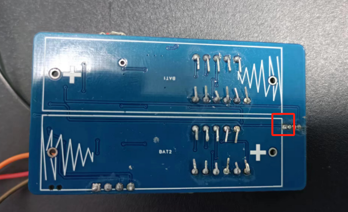
check whether the two IO ports p8 and p9 of the i2c function are shorted. They may be directly shorted or the pins of the temperature and humidity module base may be shorted. (The problem was found here, the temperature and humidity module base has two shorted solder joints)
Write the program, run the i2c function, use a multimeter to measure the pin output to see if it is normal.
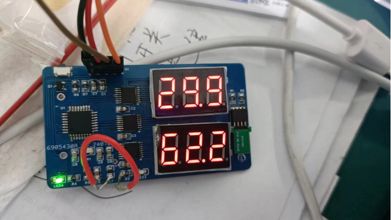
After clearing the solder joints, rewrite the program and it will display normally.
(10) After downloading successfully once, the download fails again.
After writing the official program, when burning the program again, you will encounter a three-part pop-up window. This problem is because the program puts the system into a low-power mode to save power. At this time, press the button on the board to activate the program or power it on again, and you can write it. This problem is encountered by many friends in the group. I hope that people who copy it later will pay attention to it.


After going through eighty-one difficulties, I finally succeeded!
7. The BOM list
is attached.


 京公网安备 11010802033920号

 ESMH6R3VSN273MQ30S


