1. Project Introduction: This project presents
a simple LCD1602 temperature electronic clock designed based on the STC89C89C52RC-40I-PDIP40 microcontroller. The overall PCB size is the same as the LCD1602 screen size (80×37mm). It features real-time time and temperature display, and three buttons control time setting/increment/decrement. A buzzer sounds when a button is pressed.
2. Overall Design :
This simple LCD1602 temperature electronic clock uses the STC89C89C52RC-40I-PDIP40 microcontroller. It has a 5V power input and uses a 6-pin Type-C interface. The buttons use a 6×6×6mm horizontal package. A buzzer sounds when a button is pressed. It employs a DS1302 real-time clock chip and a DS18B20 temperature sensor to detect the current temperature. The LCD1602 screen displays the real-time time and temperature.
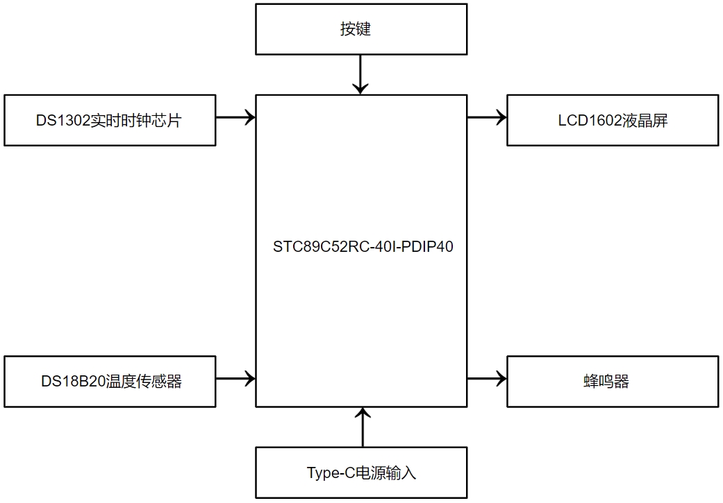
Figure 2-1 Simplified LCD1602 Temperature Electronic Clock System Block Diagram
3 Hardware Design
3.1 Power Supply Circuit The
power supply uses a 6-pin Type-C interface, and C1 is the power supply filter capacitor.

3.2 Microcontroller Minimum System Circuit The main
controller uses the STC89C52RC-40I-PDIP40 microcontroller, which is plug-in packaged for easy soldering. The P0 port is special because it has no internal pull-up resistors, so an external pull-up resistor of 4.7K~10K is required when using it as an I/O port. When P0 is used as an address/data multiplexed bus, it uses the lower 8 address lines [A0~A7] and the data lines [D0~D7], in which case no external pull-up resistor is needed. Regarding EA# (the EA# pin is internally pulled up to VCC), if no external pull-up is added or if it is externally pulled up to VCC, the microcontroller will start executing the program from the internal source after power-on reset; if it is externally pulled down to ground, the microcontroller will start executing the program from the external source after power-on reset.
An external RST pin reset is used, with a 10uF capacitor and a 10kΩ resistor. Pressing the RST1 button pulls the RST reset pin high; releasing the button pulls it low, generating an external reset pulse to reset the system. This signal source, which generates a reset by pulling the reset pin high, needs to be held for 24 clock cycles plus 10us to produce a reset. Pulling the RST pin low then ends the reset process, and the microcontroller begins normal operation from address 0000H in the user program.
The crystal oscillator provides the clock signal for the microcontroller's minimum system. The crystal oscillator frequency X1 is selected as 11.0592MHz, and the resonant capacitor is 47pF to ensure a more stable output oscillation frequency.

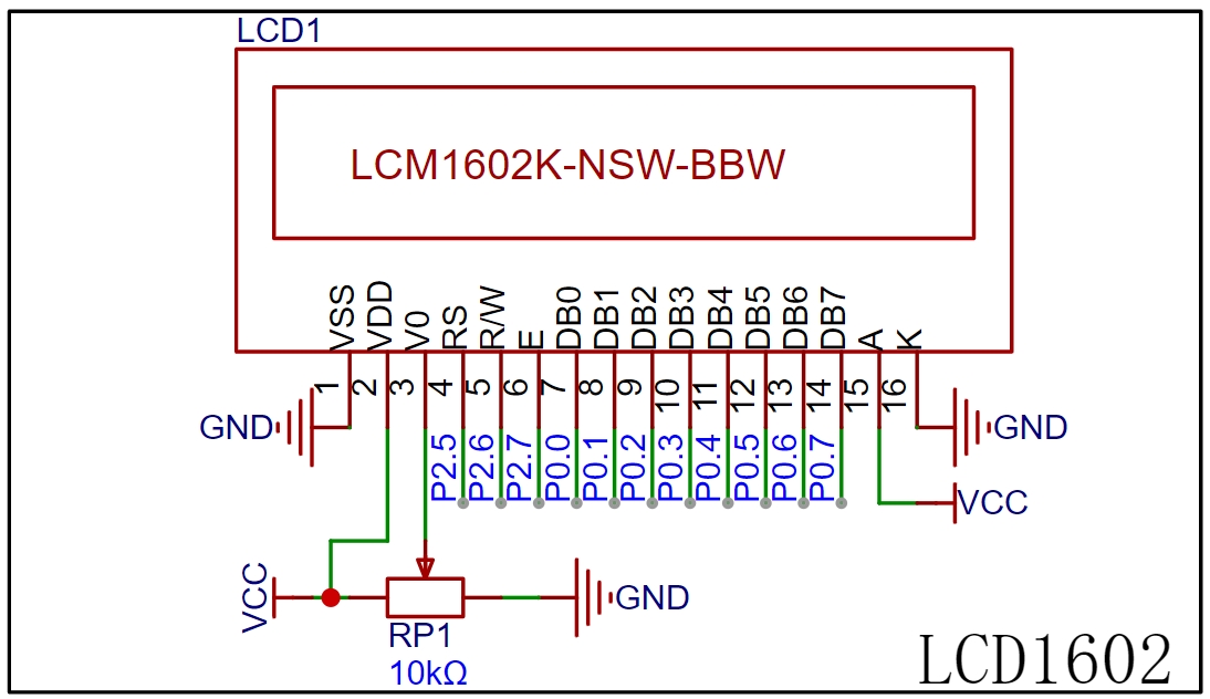
3.3 LCD1602 LCD Screen
The LCD1602 LCD screen has low power consumption and connects directly to the P0 port and P2.5, P2.6, and P2.7 of the main control microcontroller. The power supply directly uses the Type-C input VCC (+5V). V0 is the contrast adjustment terminal of the LCD1602 LCD screen; the display contrast can be changed by adjusting the resistance value of the adjustable resistor RP1. Excessive contrast will produce ghosting.
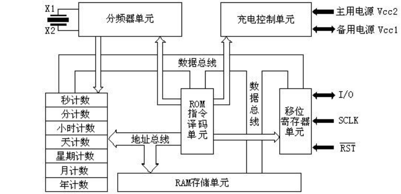
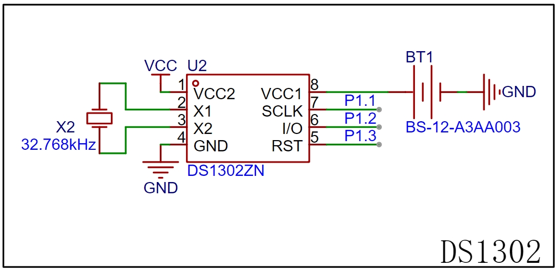
3.4 DS1302 Real-Time Clock
The DS1302 real-time clock chip can count seconds, minutes, hours, days, weeks, months, and years with leap year compensation. It uses synchronous serial communication, requiring only 3 lines: RST (reset), I/O (data line), and SCLK (serial clock). The DS1302 can operate with very low power consumption, consuming less than 1µW to store data and clock information.

VCC2 (main power) is directly connected to the Type-C input VCC (+5V). VCC1 (backup power) is connected to a 3V CR1220 button battery for backup, ensuring time and data storage in the absence of main power. When VCC2 is greater than VCC1 + 0.2V, the DS1302 is powered by the VCC2 main power supply; when VCC2 is less than VCC1 + 0.2V, the DS1302 is powered by the VCC1 backup power supply. The DS1302's crystal oscillator is directly connected to 32.768kHz. SCLK (serial clock input), I/O (data input/output), and RST (reset) are directly connected to the microcontroller's P1.1, P1.2, and P1.3 pins, respectively.
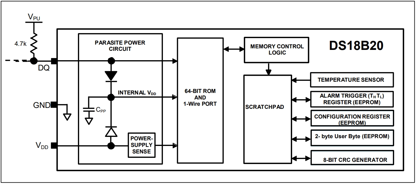
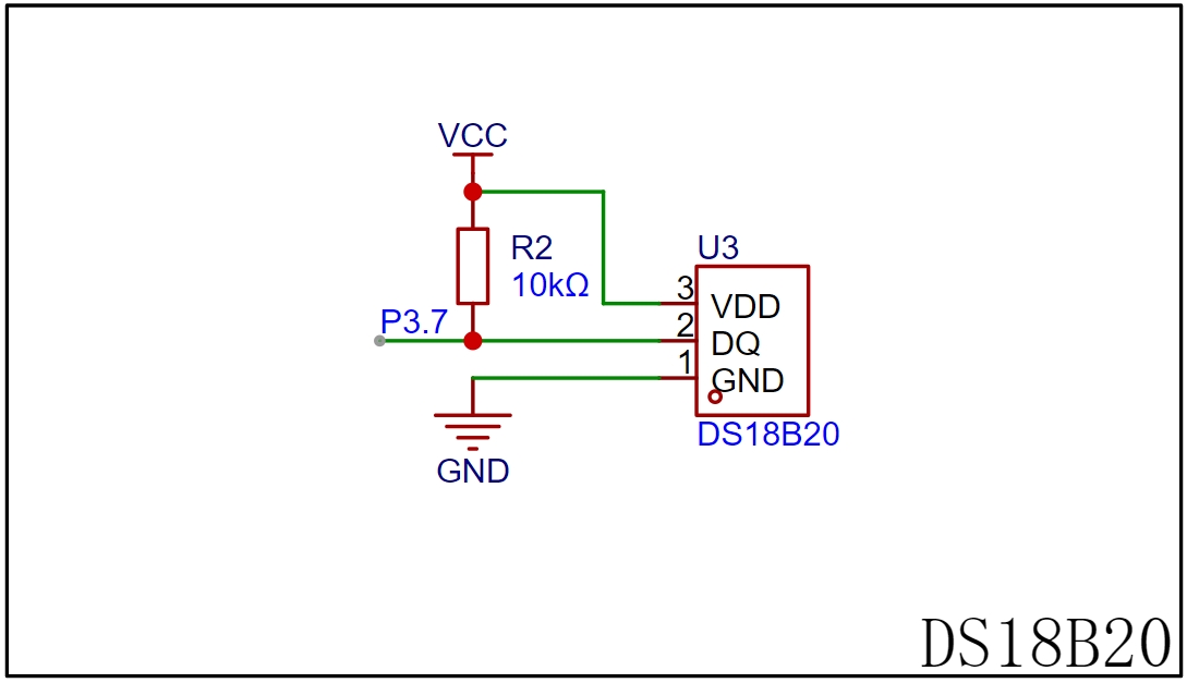
3.5 DS18B20 Temperature Sensor
The DS18B20 temperature sensor provides 9- to 12-bit resolution temperature measurement. It uses a single-bus protocol and communicates with the microcontroller's P3.7 port through a single-wire port (DQ), requiring a weak pull-up resistor.
3.6 The buzzer circuit
uses the P1.0 port of the microcontroller for control. Since the microcontroller's drive current is limited, a digital transistor can be added to drive it, improving the output capability. Here, an NPN 8050 transistor is selected. When the transistor operates in switching mode, it amplifies the drive current, causing the buzzer to emit sound.

3.7 The button
circuit consists of three independent buttons, directly connected to the P2.2, P2.3, and P2.4 ports of the microcontroller. The other side and the button mounting pin are connected to GND, enabling the microcontroller's internal I/O pin pull-up mode. The default pin is high; if a button is pressed, the pin connects to GND, resulting in a low level. The button press is checked by verifying the corresponding microcontroller I/O pin is low. To prevent false triggering, debouncing can be implemented in software.

3.8 The download
interface uses the UART communication protocol for serial programming. It has four pins, using TTL levels: low level is 0 (0V), and high level is 1 (5V). A microcontroller's serial port typically has two ports: a TXD transmitter and an RXD receiver. When connecting a USB-to-TTL cable, ensure proper cross-connection; that is, connect the RXD end of the USB-to-TTL cable to the TXD end of the microcontroller, and vice versa.


4. Schematic Design:
Open JLCPCB EDA, create a new project and name it "[Microcontroller] Simple LCD1602 Temperature Electronic Clock," and name the schematic file "SCH." Draw the circuit schematic based on the following circuit.

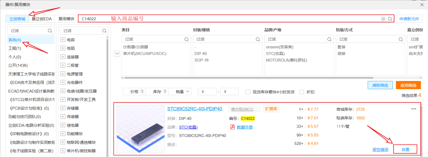
In this project's component selection, all components can be placed directly by pressing Shift+F. Click on the LCPCB online store, copy the product number (Supplier Part) from the Bill of Materials (BOM), and search (each component has a unique product number in the LCPCB online store). If a component is out of stock, other alternatives can be selected. Through the analysis of the above circuit, you should now understand the role of each component in the circuit. Replacing individual components will not affect the circuit's performance. Understanding the circuit's operating characteristics simplifies circuit selection.
5.
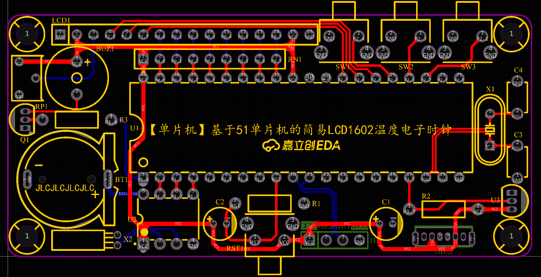
After completing the schematic design and verifying the correct circuit and network connections, click "Design" → "Convert Schematic to PCB" in the top menu bar (shortcut key is Alt+I). Then save the PCB file to the project file and name it: PCB.
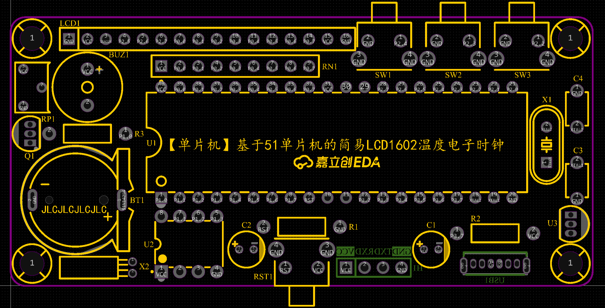
Click "Placement → Board Frame → Rectangle" to place and draw the board frame outline (80mm×37mm). You can add a 2mm corner radius.

Figure 5-1 Board Frame Design
After drawing the board outline, the next step in PCB design is to classify and lay out the components. Classification refers to categorizing the components according to the functional modules of the circuit schematic. The schematic has many buttons and external interfaces. Here, we need to use the layout transfer function provided by JLCPCB EDA. First, ensure that the PCB project has been saved in the same project folder as the schematic file. Then, select a circuit module in the schematic, such as the button circuit. Then, click "Design" → "Cross Selection" in the top menu bar (shortcut key is Shift+X). The corresponding components on the PCB page will then be selected and placed according to the schematic layout. After classifying the various circuit modules using this method, place them sequentially in the previously placed borders.
After completing the layout, the next step is PCB routing. You can click on the single-path routing tool in the routing toolbar to connect lines (shortcut key Alt+W). By default, the top layer is red and the bottom layer is blue. Prioritize routing the top layer. If a path is blocked, switch to the bottom layer for connection. Thicken the power supply to 25mil. During routing, prioritize straight lines. Use rounded bends or obtuse angles for curves. After completing all net and flyline connections, add teardrops and copper pours, as well as silkscreen annotations.
After completing the PCB design, you can go to JLCPCB to place a free order for prototyping.
6. Instructions for Use:
Press the SW1 button to enter the time setting calibration mode. The time on the LCD1602 screen will flash to show the position of the currently selected time setting. Press the SW2 button to increment by 1, and press the SW3 button to decrement by 1. After completing the setting, you can press SW1 to move to the next setting position in the order of "year → month → day → hour → minute → second → OK".


 京公网安备 11010802033920号

 ISL9014AIRFDZ


