Video link
: https://www.bilibili.com/video/BV1jRbNekE63/?vd_source=088ad4dedbbd5d327a72a2c32b269d5e
Introduction:
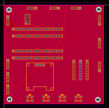
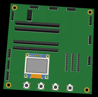
The annual graduation project season is approaching. To help graduating students next year create their projects, I've developed a universal course/graduation project board based on STM32, designed to help students quickly build, debug, and verify their systems.
Advantages
: 1. Modular design, no surface-mount components, plug-in soldering and debugging, suitable for beginners.
2. All I/O ports are brought out for easy expansion
. 3. Reserved 5V and 3.3V power interfaces for convenient module power supply.
4. Supports
most commonly used sensors in course projects/graduation projects (90% verified OK)
. 1. Input modules: Temperature, humidity, smoke, gas, pyroelectric, light, raindrop, flame, water level, water quality TDS, infrared phototransistors, buttons, touch, serial port, through-beam optocouplers, infrared remote control, weighing module, pressure, voice recognition, gesture recognition, heart rate, accelerometer, fingerprint recognition, RFID card...
2. Output modules: OLED display, relay, LED, fan, servo motor, vibration motor, buzzer, stepper motor, infrared remote control, RGB light, PWM dimming...
3. IoT: WiFi, Bluetooth/BLE, LoRa (1-to-1, 1-to-many), 4G, GPS, IoT, SIM module...
4. Cloud Platforms: OneNET, Alibaba Cloud, Gizwits, Buffalo Cloud...
5. Apps: Android, WeChat Mini Program, Blinker...
6. Host Computer: Python, QT...
7. Artificial Intelligence: K210 Face Recognition, License Plate Recognition, Deep Learning...
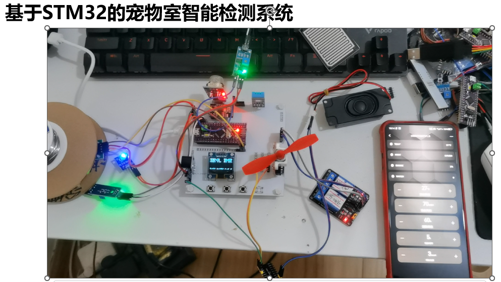
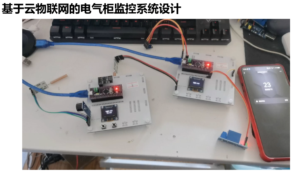
We also provide some topic suggestions and project demonstrations. Brief demonstrations of the projects are included in the videos.
If you have any questions about topic selection, are undecided, or have other needs, you can add my personal WeChat for one-on-one communication.


PDF_STM32 Graduation Project Universal PCB Board.zip
Altium_STM32 Universal PCB Board for Graduation Project.zip
PADS_STM32 Universal PCB Board for Graduation Project.zip
BOM_STM32 Universal PCB Board for Graduation Project.xlsx
93642
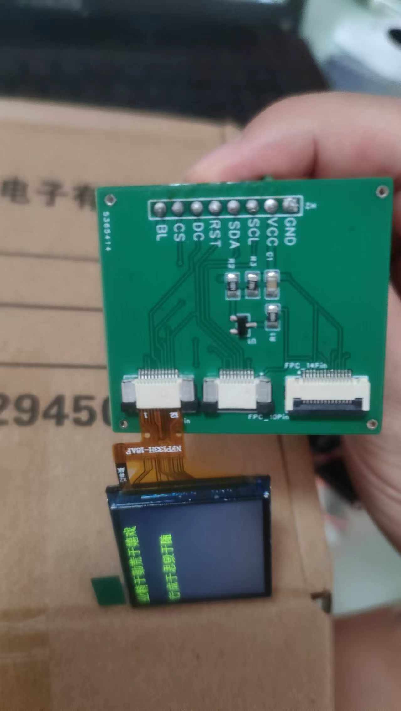
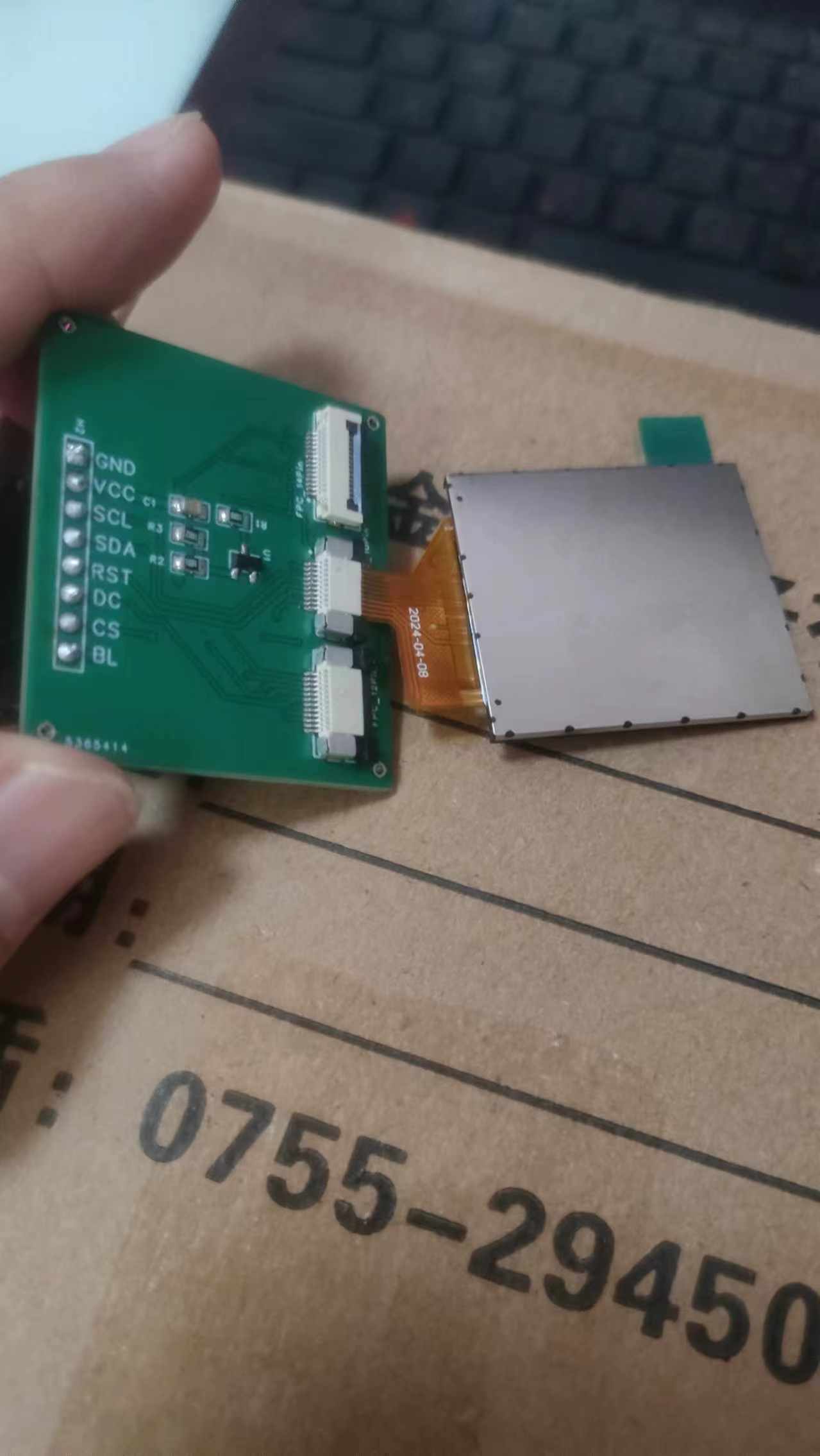
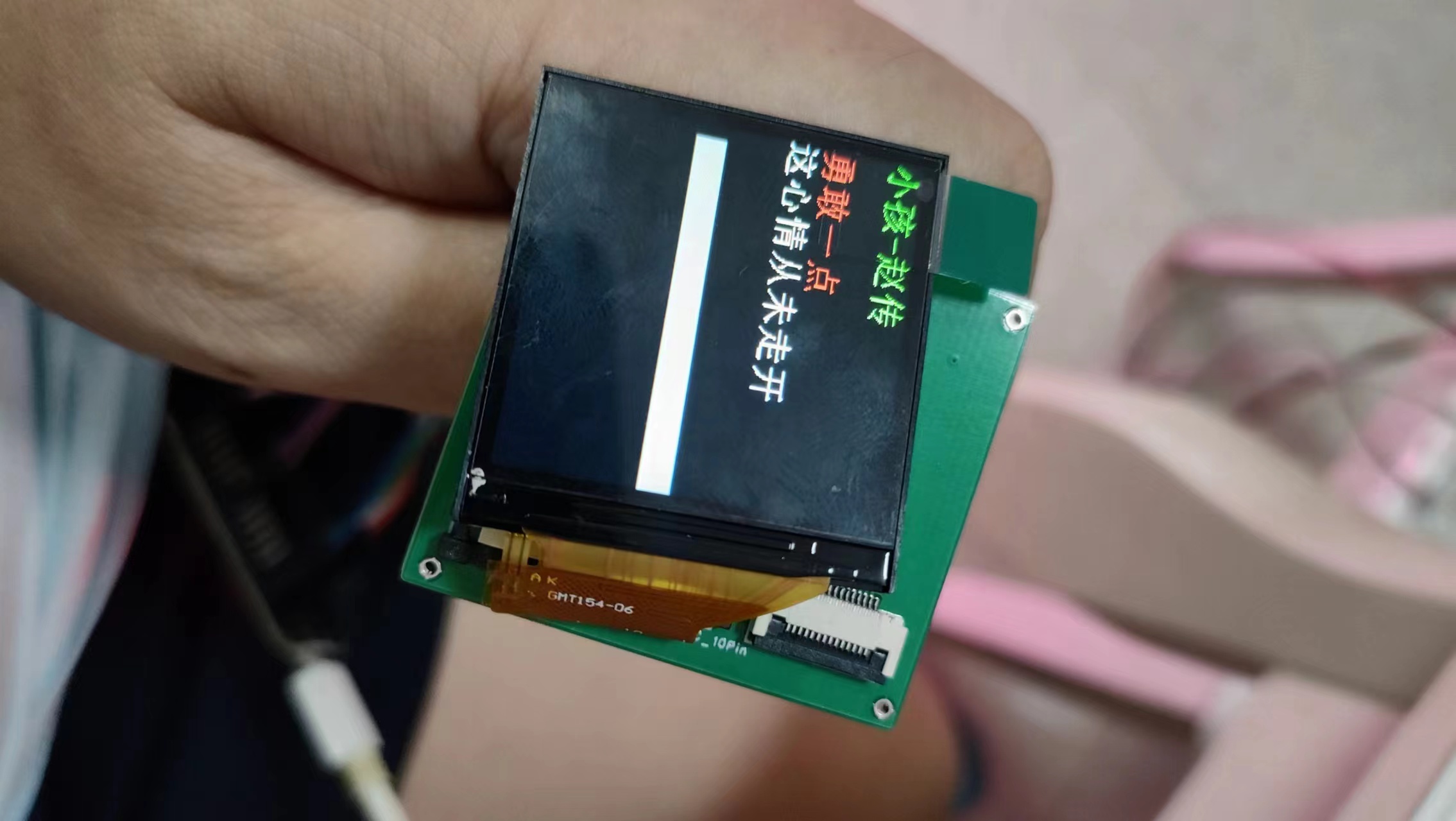
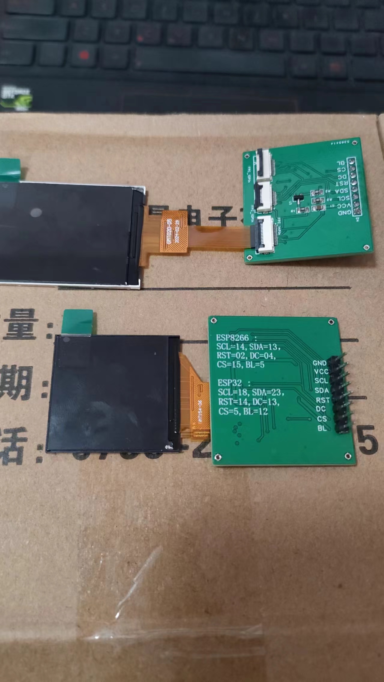
tftDriver
The SPI TFT driver board supports multiple pin types: 10-pin, 12-pin, and 14-pin.
Everyone needs a display screen. 7-pin or 8-pin TFT screen modules sold online are not cheap, but screens without a driver board are very cheap. We should save money wherever possible.
On the other hand, the pins of the screen will affect the space. Theoretically, soldering is the most space-saving method, but the soldering is really bad, so we can only use FPC connectors.
Before making this, I was intimidated by TFT driver boards. I had previously made a driver board for a transparent screen, but failed when boosting to 12V. Various TFT screens online, even those based on SPI communication, have numerous pin configurations: 10-pin, 12-pin, 14-pin...
I honestly couldn't understand the differences. Making this driver board was purely to verify the circuit's versatility, and I encountered countless pitfalls.
Let me talk about those pitfalls:
1. The pinout is reversed. I'm used to using a flip-flop FPC, but its pinout is reversed compared to the screen's. Therefore, it's best to prepare two types of FPC connectors: both top and bottom connectors. This way, it can still be used even with reversed pinouts.
2. This design shares power with the MCU. Consider a separate step-down power supply to avoid affecting MCU stability.
3. The screen's FPC cables have different orientations; the connection side might be reversed compared to the display side. It's recommended to buy the screen first; consider the placement of the FPC socket based on the length of the FPC cables.
PDF_tftDriver.zip
Altium_tftDriver.zip
PADS_tftDriver.zip
BOM_tftDriver.xlsx
93643
[Community Edition - Geocentric] cw32f030c8t6
[Community Edition - Geostar] This is the Community Edition full-pin CW32F030C8T6
[Community Edition - Ground Star] CW32F030C8T6 All Pins Pulled Out. Features of this community edition: 1. All pins are pulled out, suitable for all-around development using the CW32F030C8T6. 2. Complete power supply; power flow is considered in the wiring layout, allowing direct power supply via expansion board via headers. 3. Pin spacing is consistent with the LCSC Ground Star version. 4. Three debugging LEDs. Developers only need to connect DuPont wires to the corresponding pins to directly use the LEDs for testing, greatly facilitating testing for solder joint defects and simple code verification. 5. Comfortable RESET button. 6. Aesthetically pleasing.
Flexible Lighting Video.mp4
PDF_[Community Edition - Geocentric] cw32f030c8t6.zip
Altium_[Community Edition - Geocentric] cw32f030c8t6.zip
PADS_[Community Edition - Geocentric] cw32f030c8t6.zip
BOM_[Community Edition - Geocentric] cw32f030c8t6.xlsx
93644
VFD clock based on STM32G0
A desktop clock made using an STM32G030F6P6, DS3231, and a VFD display.
Features:
High-precision clock chip,
Type-C external power supply,
VFD display module. Stylish colors.
Regarding the VFD display module:
The VFD uses a driver-equipped module [8-bit standard module], link:
[Taobao] https://m.tb.cn/h.gRSBszRKSWjYMjH?tk=ynoH3c7G65H HU9196 "Arduino C51 STM32 VFD display module 8-bit dot matrix display module VFD fluorescent screen serial port"
Click the link to open directly or search on Taobao.
The advantage of using the module is that you don't need to write your own VFD driver; SPI can be used.
Power-off timekeeping
uses a CR2032 button battery to power the clock chip, ensuring normal timekeeping even after power loss.
Board connections
use dual-channel M210 copper pillars and PM24MM screws connected through mounting holes. The main controller and module are connected using pin headers and sockets. The height of the pin headers and sockets is slightly higher than the copper pillars, but the impact is not significant; if you mind, handle it yourself. There was
a hardware bug
: the I/O panel didn't show pull-up resistors. I'm not sure if the built-in pull-up resistors on the STM32G0's I/O pins are even useful, so I added two jumper wires. (This was a project I did a long time ago, and I haven't looked into it in detail.)
lv_0_20230713004119.mp4
PDF_STM32G0-based VFD Clock.zip
Altium_VFD Clock Based on STM32G0.zip
PADS_VFD Clock Based on STM32G0.zip
BOM_VFD Clock Based on STM32G0.xlsx
93645
STC Bluetooth Remote Control Toy Car
This is a toy car. The STC8H8K64U is used as the control chip, and the L298N chip is used as the motor driver. The power is provided by two 3-6V input DC motors. The HC-06 Bluetooth module provides communication between the car and a smartphone.
This is a toy car, easy to build and fun to play with. The cost is approximately 50 yuan (the chassis and motor were donated by a friend and are not included in the cost; this project only includes the car's control circuitry, not the frame and motor, which can be customized). To control costs, the STC8H8K64U core board (the "dog-beating stick") can be replaced with an STC8H8K64U-PDIP40 (a separate programmer is required for programming). The PCB has a pre-installed interface for an infrared tracking module, which can be installed independently. The program and Bluetooth debugging app are provided in the attachment.
Due to my limited skill, there are bound to be errors and shortcomings in this project; corrections are welcome.
stc8h8kproject.zip
b0c7f4e7c8786803aa7a3092d8740a72.mp4
Bluetooth debugger.zip
PDF_STC Bluetooth Remote Control Toy Car.zip
Altium_STC Bluetooth Remote Control Toy Car.zip
PADS_STC Bluetooth Remote Control Toy Car.zip
BOM_STC Bluetooth Remote Control Toy Car.xlsx
93646
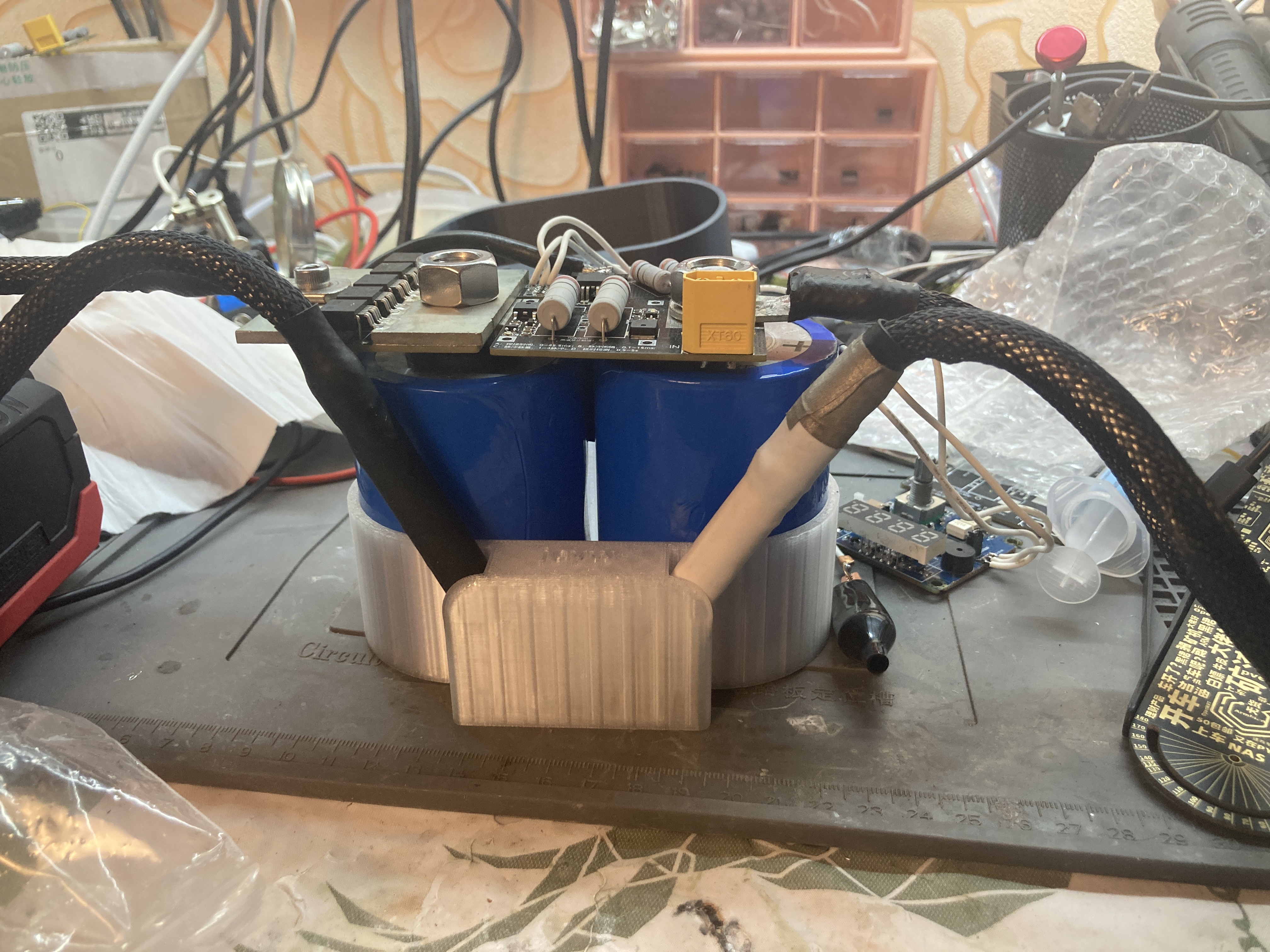
jcyw Digital Players - Supercapacitor Spot Welding Machine - Modular Plan 2.0
This project is defined as the modular version 2.0 of the spot welding machine, because the previous modular version 1.0 made good progress and still uses the four main components: control board + MOSFET + explosion protection + equalization.
This project is defined as a modular 2.0 version of a spot welding machine. Because the previous modular 1.0 version made good progress, and I've met many friends through this platform, I'm now releasing a new circuit diagram. It still uses the four core components: control board + MOSFET + explosion protection + equalization. If you're interested, please leave a message; I won't post the group number.
I've been working with spot welding machines for about a year, experiencing many things, various schools of thought, and different design approaches. Some focus on bulking components, some on simplification, but many only build one or two modules, resulting in less than satisfactory results.
Regarding the spot welding current, the measured effective value is 3kA. I don't really know what this current can weld; I've only welded a 0.2mm copper strip bare, and the effect is shown in the picture. However, to lower the expected threshold, I've tentatively set it at 2-2.5kA.
Regarding accessories and peripherals, I've developed related bases, housings, etc., which enhance the enjoyment and are a nice bonus in my busy schedule.
In response to everyone's requests, I've re-uploaded the schematic and PCB; they should be correct, but you'll need to verify them yourself.
Thank you!
WeChat_20240420025403.mp4
PDF_jcyw Digital Player_Supercapacitor Spot Welding Machine_Modular Plan 2.0.zip
Altium_jcyw Digital Player_Supercapacitor Spot Welder_Modular Plan 2.0.zip
PADS_jcyw Digital Player_Supercapacitor Spot Welding Machine_Modular Plan 2.0.zip
BOM_jcyw Digital Player_Supercapacitor Spot Welding Machine_Modular Plan 2.0.xlsx
93647
jcyw Digital Players - Supercapacitor Spot Welding Machine - Modular Plan 1.0
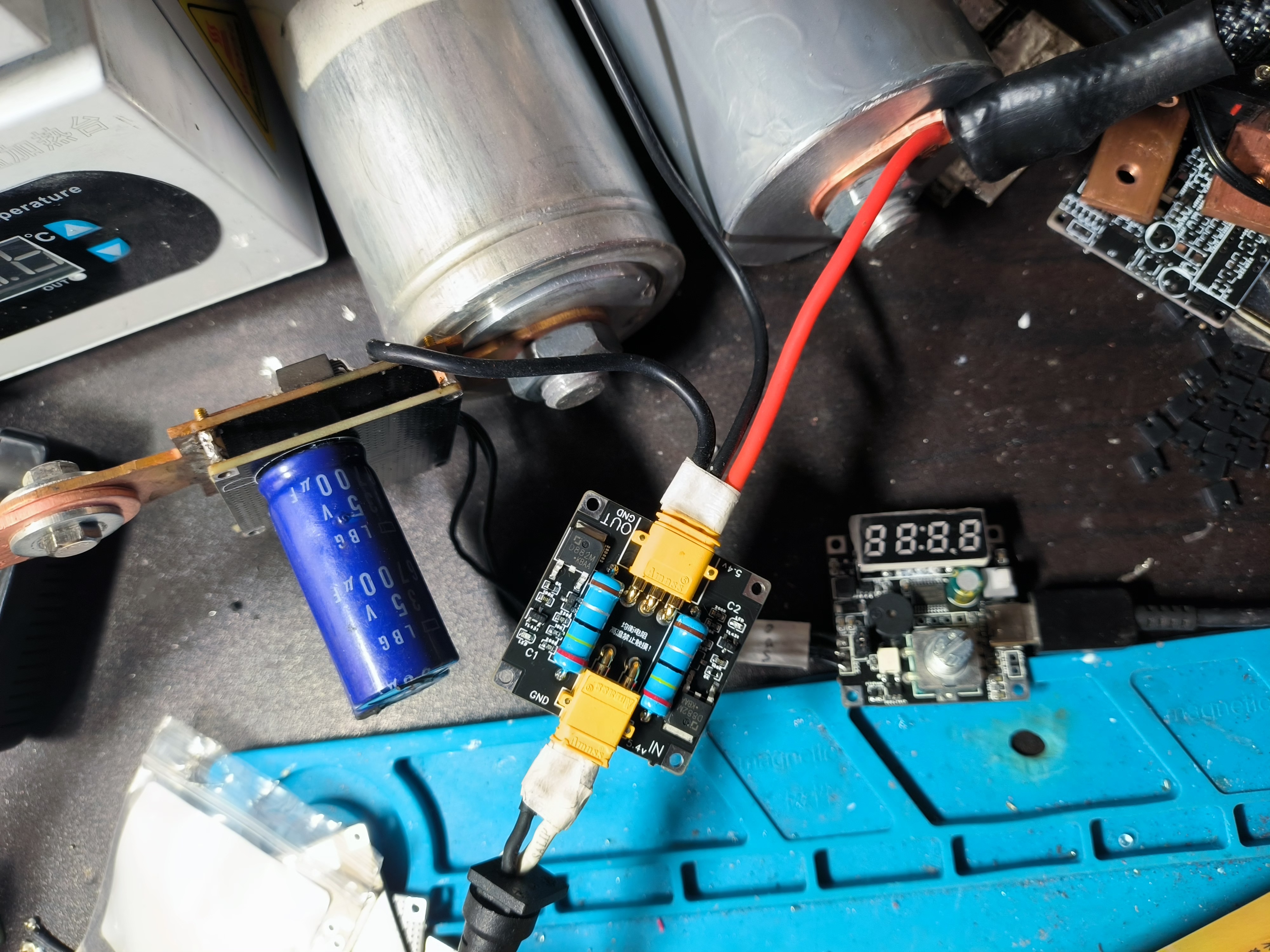
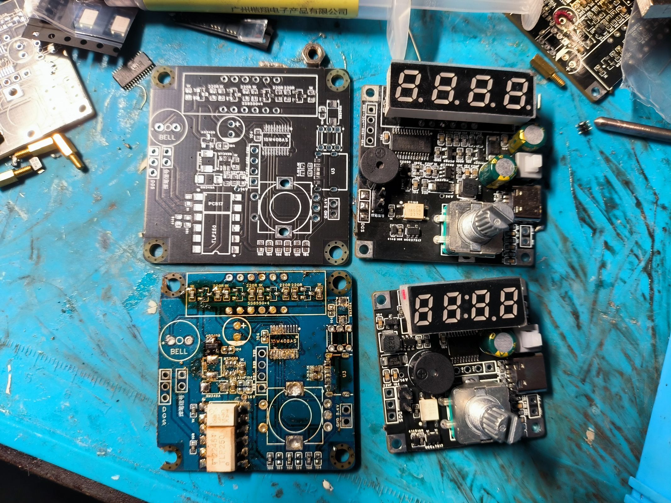
Based on the open-source versions of supercapacitor spot welding machines provided by experienced forum members, and incorporating my own understanding, this version is the modular design plan 1.0.
Based on the open-source versions of supercapacitor spot welders shared by forum experts, and incorporating my own understanding, this version is Modular Project 1.0. The iterative development of the Modular Project continuously feeds back into subsequent integrated versions and various variant models. Through modular design, changes to one part do not affect the whole.
Friendly reminder: In response to requests, the schematic and PCB have been re-uploaded; they should correspond, please verify yourself.
The following is a brief introduction to Modular Project 1.0:
Modular spot welder (control + MOSFET + explosion protection + equalization), 0.2mm copper, 1.0mm iron sheet, 3-4kA overall internal resistance 1.3mR, PCB self-designed, 42*42mm/36*36mm ultra-small board, modular design, multi-layer stacking, achieving various forms, firmware can be flashed with the open-source version or other open-source firmware. Performance: Can weld up to 0.2mm copper/1.0mm pads. Highlights: 1. Single-sided board design, convenient for heating table processing. 2. Type-C 5V power supply. 3. Open nose directly connects to capacitor tabs, eliminating intermediate steps and reducing internal resistance. 4. Simple and efficient, lowering the barrier to entry and making it accessible to the general public. Continuously being updated.
Some theoretical knowledge can be referenced: 1. Internal resistance calculation: The system consists of several parts: soldering cable + soldering pen + main control board + MOSFET board + supercapacitor. Soldering cable: 16 sq mm 1.25 mΩ / 25 sq mm 0.8 mΩ / 35 sq mm 0.6 mΩ; Soldering pen: 0.3~1 mΩ (all copper will be much smaller, brass clips are slightly larger); MOSFET board: 0.1~0.05 mΩ (a single MOSFET 228/8409 is 0.6 mΩ, for 6~12 transistors in parallel, divide by the number 6~12); Supercapacitor: 0.3~1.2 mΩ (a single supercapacitor is 0.3, series and parallel connections reduce, for example, two series are 0.3*2=0.6, two series and two parallel are 0.3*2/2=0.3, and so on). Total internal resistance sum: 0.8 + 0.3 + 0.05 + 0.6 = 1.75 milliohms. This is the ideal state. In reality, there is also the internal resistance of the connecting copper busbar screws, which is calculated as 2.5 milliohms. 2. Spot welding current calculation: Voltage of two series capacitors 5.4V / 2.5 milliohms = 2000A. This is the peak value under ideal conditions. The actual value needs to be measured with instruments. Note: For large-scale spot welding, it is best to charge and use simultaneously to maintain a voltage of 5.4V.
Please see the pictures and videos for the effect.
Let's make friends through playing and popularize spot welding. The vision is that everyone can play with spot welding machines. Welcome to exchange ideas. Please leave a message. I will not post the group number.
Thank you.
Below are some photos for reference. Please indicate the source when reprinting. Thank you.

WeChat_20240220023419.mp4
PDF_jcyw Digital Player_Supercapacitor Spot Welding Machine_Modular Plan 1.0.zip
Altium_jcyw Digital Player_Supercapacitor Spot Welder_Modular Plan 1.0.zip
PADS_jcyw Digital Player_Supercapacitor Spot Welding Machine_Modular Plan 1.0.zip
BOM_jcyw Digital Player_Supercapacitor Spot Welding Machine_Modular Plan 1.0.xlsx
93648
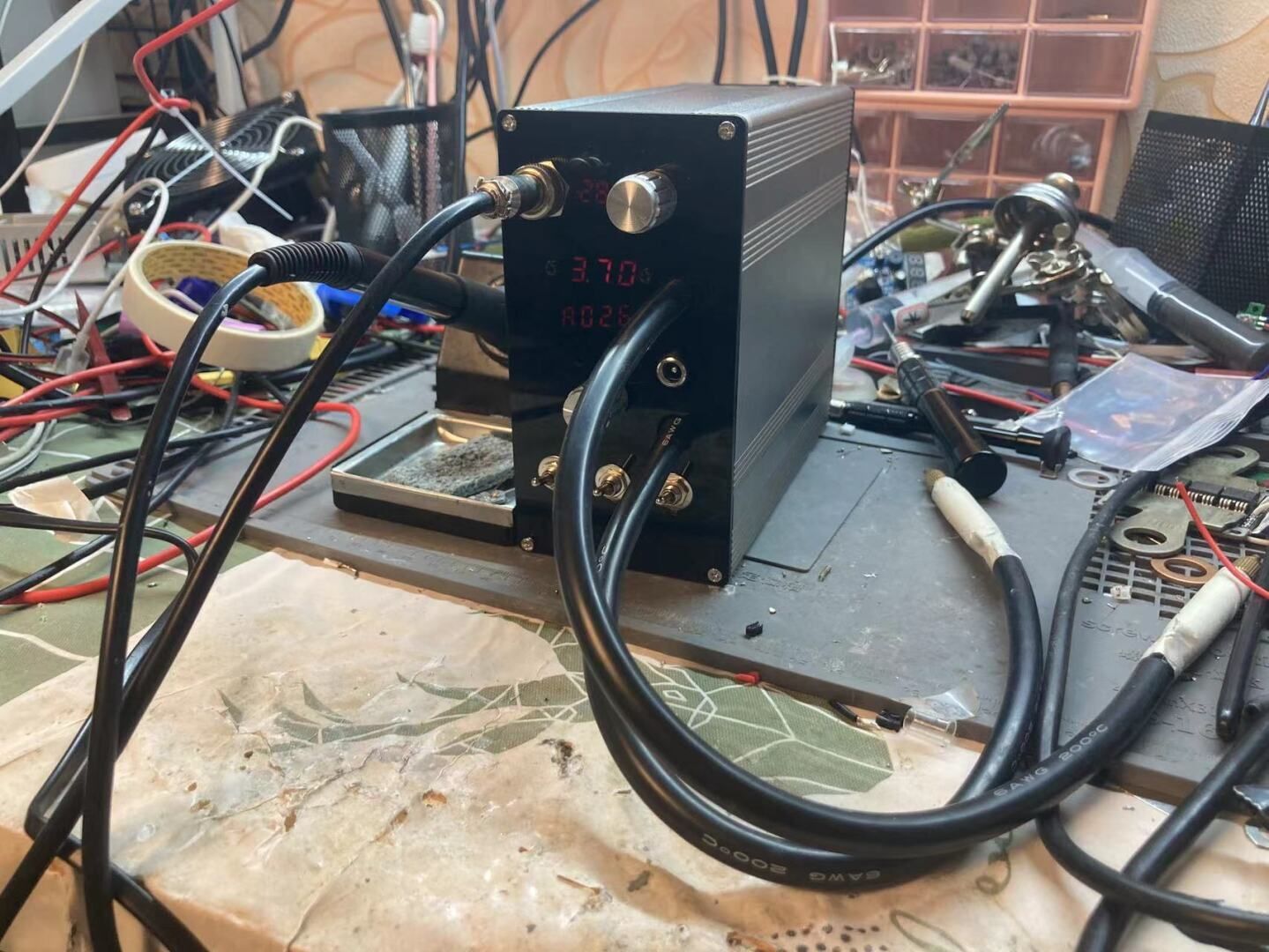
jcyw Digital Players - Supercapacitor Spot Welding Machine - Modular Design 3.0
Time flies. It's been over a year since I started using spot welding machines. The modular plan 3.0 is now available, a two-in-one spot welding and soldering all-metal shell version. The days of running naked are over; the era of multi-functionality is coming.
Time flies. It's been over a year since I started working with spot welding machines. The Modular Project 3.0 is now available—a multi-functional all-metal version combining spot welding and soldering. The days of bare metal are over; the era of multi-functionality is here. Current is between 2-2.5kA. Please enjoy the high-resolution images. Welcome to discuss; please leave a message (no group number posted).
PDF_jcyw Digital Player_Supercapacitor Spot Welding Machine_Modular Plan 3.0.zip
Altium_jcyw Digital Player_Supercapacitor Spot Welder_Modular Plan 3.0.zip
PADS_jcyw Digital Player_Supercapacitor Spot Welder_Modular Plan 3.0.zip
BOM_jcyw Digital Player_Supercapacitor Spot Welding Machine_Modular Plan 3.0.xlsx
93649
electronic


 京公网安备 11010802033920号

 MI-PC6WZ-MY


