A friend recently asked me to design a wireless remote control device. The requirement was that the remote control, using two buttons, could control a motor to rotate back and forth within a 2-3 meter range. Because it needed to be mass-produced, cost control was crucial in addition to functionality. Luckily, STC and JLCPCB were hosting a microcontroller creative design competition, so I decided to use STC's MCUs for this project. I designed two versions: one using the STC8H8K64U, focusing on performance, and the other using the STC8G1K08A, focusing on cost-effectiveness. **This also demonstrates the advantage of STC's rich product line, giving users ample choices.**
Considering cost, I abandoned Bluetooth and WiFi solutions and ultimately chose a 433MHz wireless communication solution.
This was my first time working with 433MHz communication. I first searched for 433MHz chips on the LCPCB online store and finally decided to use the WF480RA and WF4455TD. In the product descriptions on Taobao, the EV1527 decoder was mentioned. A quick search revealed that the EV1527 can be software-decoded, eliminating the need to purchase a separate chip.
The remote control uses a button battery, eliminating the need for a boost/buck voltage regulator module. This is largely thanks to the wide operating voltage range of the STC chip, which further reduces costs.
The motor control utilizes the same motor driver chip I used for the AbenFan, capable of outputting forward/reverse and braking signals.
With the solution finalized, I started drawing circuit diagrams, submitting them for review, securing consumable vouchers, ordering PCB fabrication, and soldering... a familiar process followed. Now it's time to write the software.
The source code has been uploaded to GitHub and is fully open source.
[https://github.com/rushairer/STCEV1527Transmitter](https://github.com/rushairer/STCEV1527Transmitter) [https://github.com/rushairer/STCEV1527Receiver](https://github.com/rushairer/STCEV1527Receiver )
[Image of receiver firmware source code](https://github.com/rushairer/STCEV1527Receiver
) 

This is the remote control, with four reserved buttons; currently only P3.0 and P3.3 are used. The pull-up resistors next to the buttons do not need to be soldered; the internal pull-up resistors of the MCU can be used directly. **
[IMG_7023.jpg]

This is the receiver. MotorA/B connects to the external motors, BAT+/- connects to the external battery, and a button is reserved on the back for extended functions, such as learning pairing.
A casing was also designed for the remote control.
![IMG_7022.jpg]

Refer to the attached video for the project's running effect.
**Project Highlights:**
---
My previous understanding of STC was limited to turning on an LED, so I was a bit lost when it came to a specific project. No choice but to learn on the spot. I asked a senior member in the group to help me get an STC8G for SDCC header file. After configuring the basic environment, I used basic GPIO to get the remote control sending signals and the receiver receiving signals working.
I was stuck on writing the EV1527 software decoder for two days. I searched for a lot of relevant information online, first understanding the interaction process of the EV1527 protocol, and then searching for a lot of code shared by others, reading the code one by one.
I relearned STC's interrupt mechanism. For time interrupts, I first needed to determine the crystal oscillator frequency. Using an oscilloscope, I captured the signal waveform to verify my code. Even though the remote control's signal waveform was fine, I couldn't parse it. I was desperately suspecting a problem with the algorithm when, while fiddling with the oscilloscope, I remembered to measure the time difference between two waveforms. I discovered the time interval wasn't the expected 400µs, but 500µs. So I readjusted the delay interval, and the problem was solved!
![IMG_6970 2.JPG]
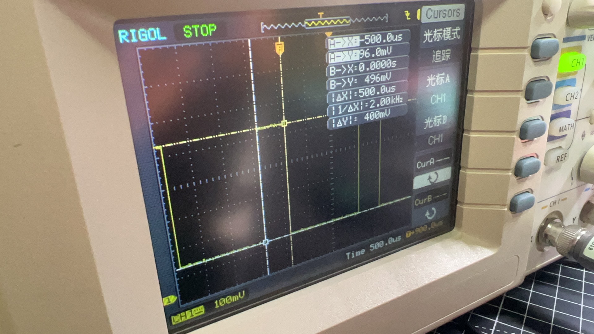
Without the oscilloscope, this project might have failed.


 京公网安备 11010802033920号

 NRU106K35


