Project Background:
As anyone who frequently uses an oscilloscope knows, the oscilloscope and its probes are like lighters—they disappear in the blink of an eye. Clearly, this happens frequently in our company as well. Oscilloscopes, probes, and even the two-pin power cord are often taken by R&D and on-site suppliers. After a year and a half, less than one-tenth of the oscilloscope probes remain. Now, I spend an hour out of my 8-hour workday searching for instruments; it's incredibly frustrating.

So, after 2.5 weeks of development, I created this toy oscilloscope.
Material Costs (Basic 3-channel 2+1):
STC32F12K54 ¥3.4,
CH343P ¥3.5,
RS624XQ ¥1.4
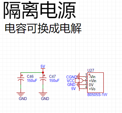
, HLK-B0505S ¥2.2
, π122M31 ¥1.5
, SMA-KWE ¥1.33,
BNC connector ¥1.48 x 2
, 8 types of 0603 resistors ¥0.35 (10 pieces) x 8
, plus other miscellaneous items ¥10 (approximately).
The total is around ¥30. For a full configuration (4+1), add another ¥5-6 for two more BNC connectors and one op-amp, and then you'll need a separate casing (or modify the circuit board to include all four BNC connectors).
Hardware Introduction:
MCU: STC32F12K54; Internal IRC oscillator frequency: 48.036MHz (using a crystal oscillator actually makes communication less effective); Serial port baud rate: 6MHz.
USB to serial port chip: CH343P;
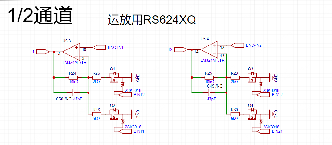
Op-amp: RS624XQ (simple amplification);
Input attenuation of channels 1-4 is fixed at 10 (channels 1 and 2 are only on the board, channels 3 and 4 are reserved for external expansion); Amplification levels include 1 (0~40.96V, 10mV resolution), 3 (0~13.65V, 3.3mV resolution), 6 (0~6.82V, 1.6mV resolution), and 8 (0~5.12V, 1.25mV resolution); Only positive voltage input is allowed;
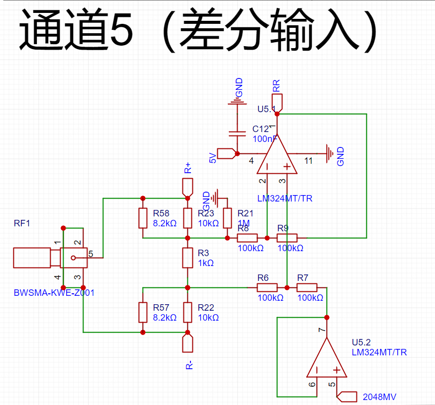
Channel 5 is a differential input, ranging from -20V to +20V, with a resolution of 10mV.
Isolated power supply and data isolation chips are used to protect the computer from explosion.
A probe purchased from Taobao for ¥16.5 is used.
Logic analyzer functionality is reserved, but not developed due to insufficient depth.
MCU: STC32F12K54, using the internal IRC oscillator frequency: Around 48MHz, after repeated downloads and adjustments, the packet loss rate was very low when the main frequency was finally around 48.036MHz. Using a crystal oscillator to multiply it to exactly 48MHz was very accurate, but it was actually easier to receive packets that weren't being received. The main issue was packet loss during microcontroller reception, but never during transmission, which was somewhat surprising. The waveform looked fine. There are two reset buttons, one on the front and one on the back.

For those with a housing, it's recommended to solder the back button; for bare circuits, solder the front button. Channels 1-4 amplification: A simple amplification was implemented using an RS624XQ, without much consideration for detail. The range can be selected via the microcontroller. Channels 3 and 4 don't need to be soldered if not needed. Channels 3 and 4 were designed to be paired with a housing, BNC-machined onto the housing, and then the fuse connected to
channel 5 on the board. Differential amplification: A simple differential amplification was implemented using an RS624XQ, with a fixed attenuation of 1/10. It was designed to measure relatively large AC signals, with a range of -20V to +20V. The SMA connector was for convenience. For external expansion, you can replace it with other
USB to serial adapters if needed: The STC32F itself supports USB communication, but in my previous tests using HID, the fastest speed was only around 200K or 300K, I forgot. One point is two bytes, so the fastest speed is probably around 100~150KSa/s. Therefore, I used a CH343 as a relay, with a maximum speed of 6M (CH340 is 2M). A 6M baud rate can meet a transmission speed of 500K, so currently continuous sampling can only achieve 250KSa/s.
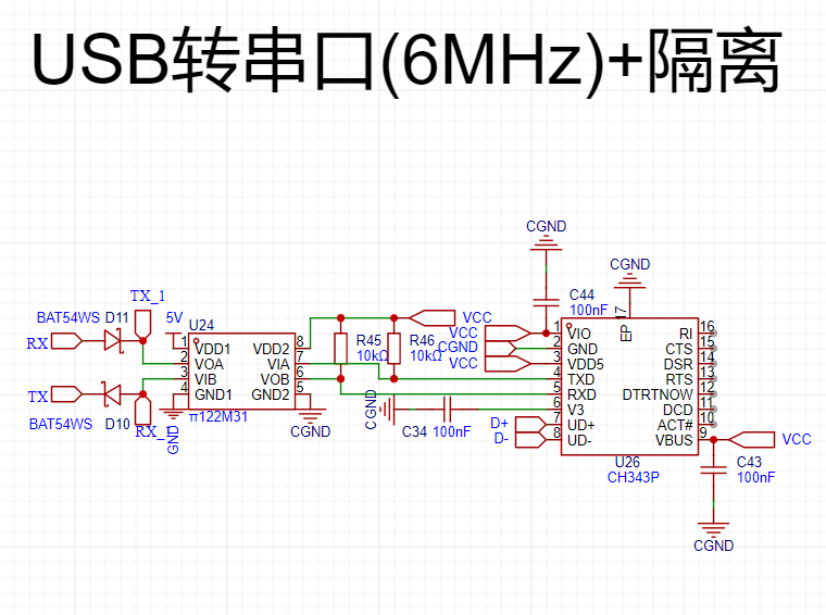
Isolation: Use an isolated power supply to avoid accidental contact with high voltage at the measurement end. Randomly take away your or your computer's
BNC input: Overvoltage protection has been added to the input. The clamping diode uses a Zener diode because I installed all the tubes I had on hand and tested them. This tube had the least leakage current. If you have other good tubes, you can replace them. If the voltage you are measuring is not too high, you can omit this diode.
The probe input is fixed at x10 with a 9MΩ resistor, which forms a 1/10 voltage divider with the 1MΩ resistor on the board. Do not adjust the thousands digit to x1. The resistance at x1 is only about 120Ω. If you accidentally measure 18V and there is no clamping diode, then you will really be sending

a sampling introduction
. This project uses a polling sampling method. Therefore, the points on different channels at the same time scale displayed on the host computer are actually delayed by 1/total sampling rate time compared to the previous channel. The theoretical interval between two points in a channel is (1/total sampling rate) × the total number of open channels. Therefore, it can only observe relatively low-frequency waveforms, but it's sufficient for my work.
Communication Introduction:
This communication protocol follows a portion of the Modbus-RTU protocol. The slave address defaults to 0XAC upon power-on, supporting continuous read and write operations, but no reply is given when writing to registers (to avoid disrupting sampling).
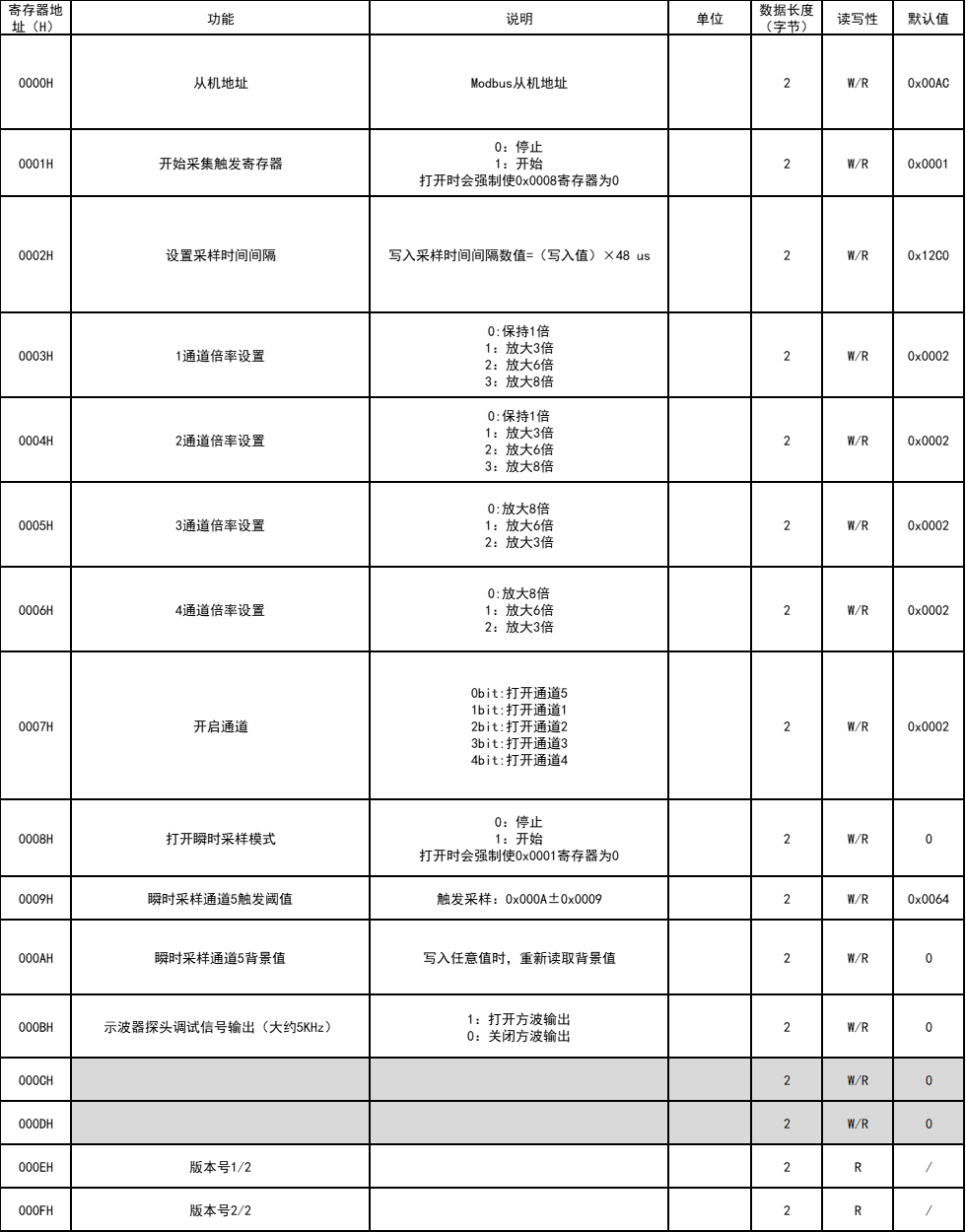
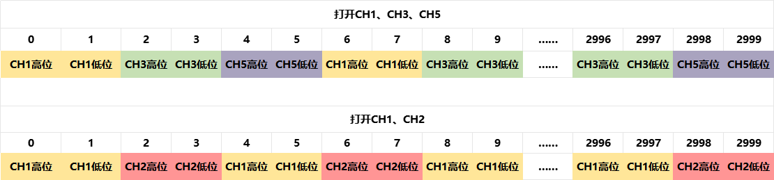
Sampled data is transmitted in 3000-byte packets (16-bit data, 1500 points). Opened channels will sequentially fill the packets with data at specified sampling intervals, sending the data once 3000 bytes are filled.
Host Computer Introduction
: First, I want to thank my good friend sdonc for completing the underlying construction of the host computer and helping me solve many problems in upper-layer development. Then, I used my 2.5 days of C# learning to write some basic code and completed the basic development of the host computer. Due to my poor coding skills, the host computer will not be open-sourced.
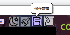
The biggest advantage of using the host computer is that waveform data can be saved! The bad news is that it consumes some memory. High-speed mode requires 100MB of memory for 11 seconds.
The host computer uses an old-school anime-themed background, with switchable dark and light themes.


It automatically identifies and connects to the slave device. Once connected, the slave device configuration can be obtained, and channels can be selected to be enabled or their multipliers adjusted via the interface. When high-speed mode is enabled, only the enabled channel with the smallest data value can be acquired.
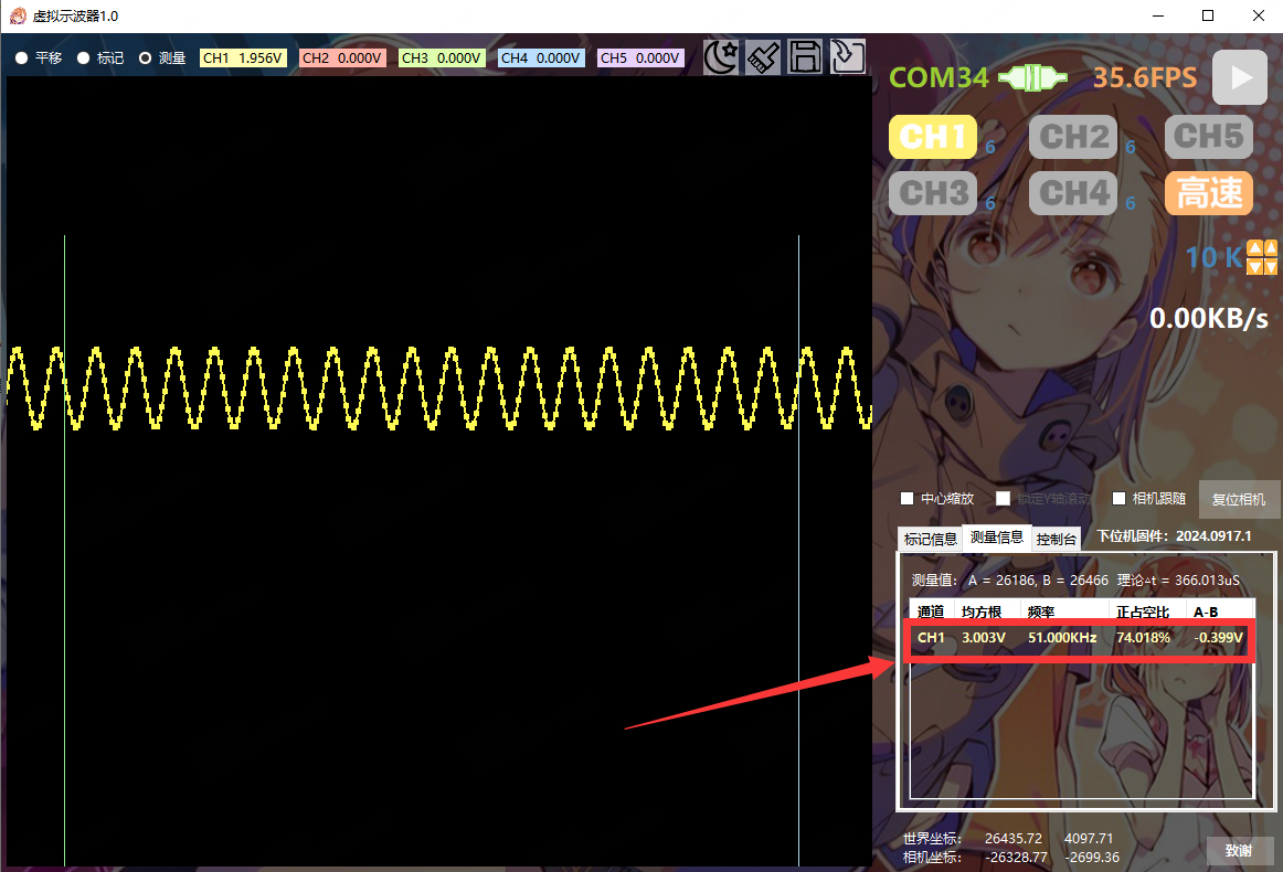
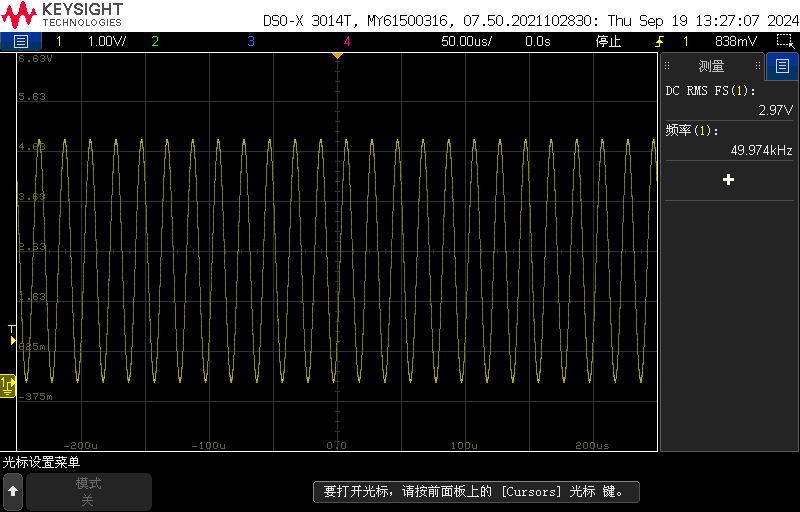
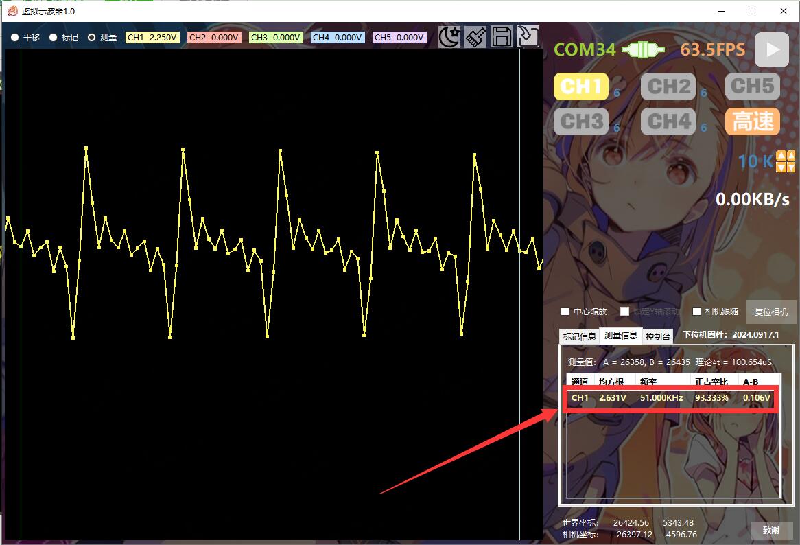
In non-high-speed mode, data is continuously acquired according to the sampling rate. When high-speed mode is enabled, channels 1-4 will only start acquiring a data packet when the voltage is above 1/8 of the range. Channel 5 will start acquiring a data packet when the voltage is greater than or less than 1V (adjustable). Inputting a
50kHz 0-5V sine wave and using high-speed measurement, compared to oscilloscope measurements, the frequency response is slightly off, but the period root mean square (RMS) results are acceptable.

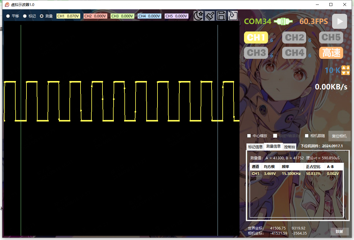
Inputting a 15kHz 0-5V multi-tone signal and using high-speed measurement yields better results.

Therefore, for detailed measurements, it's basically only possible below 15kHz; above 15kHz, it's mostly just a noise.
Inputting 15kHz 0-5V... 50% Square Wave:
The console allows adjustment of channel scaling and vertical position;

waveforms can be exported or imported for viewing;
a 5kHz square wave test signal can be enabled for probe auxiliary calibration;

channel gain can be fine-tuned; using the 4096mV reference source on the probe measurement board, the root mean square (RMS) over a period of time can be measured and compared with the theoretical value to calculate the compensation coefficient;

the interface can be zoomed using the mouse wheel, and panned while holding down the mouse wheel. The waveform refresh direction is from left to right, but when using the camera follow function, after the waveform reaches the right side of the screen, it will automatically move to the left to keep the latest waveform on the far right, similar to the oscilloscope's scrolling function.
If you encounter any problems, restart the software and reset the lower-level machine. For programming,
first
solder the main chip area, do not solder anything else. Set the programmer according to the diagram below, and then program the program through the reserved programming port. Once inside, you can use the C port to download.
Input 48 for the IRC frequency using the keyboard. After downloading, try using the host computer for control. If packet loss is severe, download a few more times; the main frequency will be automatically fine-tuned each time until the packet loss is low.

After adjusting the main frequency and confirming the effect is satisfactory, when modifying the program later, you need to uncheck the "This download requires hardware option modification" option and avoid adjusting the previously tested main frequency. The attached

instructions state that
the host computer is divided into two compressed files (each uploaded file cannot exceed 50MB). You must download both files completely before unpacking the 001 file for a complete unpacking. After unpacking, go to the directory, find the startup file, and create a shortcut to the desktop.
In conclusion
, this already meets my work needs, and there won't be any major changes in the future. At most, I'll wait for a new STC chip to come out and replace it with a more powerful one to maximize the speed.

Virtual Oscilloscope 1.0.2.zip.002
Virtual Oscilloscope 1.0.2.zip.001
32F Five-Channel Oscilloscope - Lower-Level Machine.zip
stcai-isp-v6.94H.zip
CH343 driver.zip
PDF_STC32F 5-channel toy oscilloscope (with host computer).zip
Altium_STC32F 5-channel toy oscilloscope (with host computer).zip
PADS_STC32F 5-channel toy oscilloscope (with host computer).zip
BOM_STC32F 5-channel toy oscilloscope (with host computer).xlsx
92106
Based on Zhongying SH3676010B 7-10 series 30A lithium battery protection board
The programmable IC SH3676010B from Infineon Technologies is used, with INFINEON NMOS IRL40SC228 MOS transistors. It features equalization and has been used to create 7-10 series 20-35A lithium battery protection boards. After three modifications, it has been successfully tested in production.
With the widespread application of lithium batteries in the communications industry, high performance, high reliability, and high cost-effectiveness are required for battery management systems. This product is a BMS specifically designed for power batteries, employing an integrated design. This solution is an intelligent semi-software hardware board that can implement overcharge protection, over-discharge protection, overcurrent protection, short circuit protection, and charge/discharge temperature protection.
This solution uses the Zhongying SH3676010B and can be programmed using a host computer.
Product Features:
Supports all customizable parameters, which can be written via a host computer; includes serial communication for connecting to a host computer to read battery pack information and write parameters;
supports intelligent all-time balancing, performing balancing during charging and resting, extending balancing time to improve balancing efficiency; incorporates differential pressure start balancing conditions to prevent evenly balanced cells from becoming unbalanced due to improper balancing methods, achieving 5-10 times better balancing performance than traditional methods (optional);
supports writing product numbers for easy production management and traceability (optional)
; includes load and charging checks to prevent damage to charging or discharging MOS under specific conditions; supports same-port low-voltage switch; includes
voltage detection and disconnection protection.
Function Description:
7-cell series protection;
same-port charging/discharging port;
supports undervoltage sleep mode; low-power mode (requires charging activation);
can achieve overvoltage and undervoltage protection for any cell in the battery pack;
discharge overcurrent and short-circuit protection; recovers after protection by disconnecting the load or inserting the charger.
29.4V_714F_SCH_FW_VMS_7S1P_01_A3.sch
29.4V_714F_SCH_FW_VMS_7S1P_02_A3.sch
29.4V_714F_SCH_FW_VMS_7S1P_03_A3.sch
29.4V_714F_A_PCB_FW_VMS_7S1P_01A_A3.pcb
29.4V_714F_A_PCB_FW_VMS_7S1P_02A_A3.pcb
29.4V_714F_A_PCB_FW_VMS_7S1P_03A_A3.pcb
SH367601X CV0.4A.pdf
PDF_Based on Zhongying SH3676010B 7-10 Serial 30A Lithium Battery Protection Board.zip
Altium_Based on Zhongying SH3676010B 7-10 Serial 30A Lithium Battery Protection Board.zip
PADS_Based on Zhongying SH3676010B 7-10 Serial 30A Lithium Battery Protection Board.zip
BOM_Based on Zhongying SH3676010B 7-10 Serial 30A Lithium Battery Protection Board.xlsx
92107
Voltmeter and Ammeter
The ammeter and voltmeter use a CW32 series microcontroller.
The main function used is the ADC (Analog-to-Digital Converter), also known as an A/D converter or simply ADC, which is an electronic component that converts analog signals into digital signals. A typical ADC converts an input voltage signal into an output digital signal. Since digital signals themselves do not have practical meaning, only representing a relative magnitude, any ADC needs a reference analog quantity as a conversion standard. A common reference standard is the largest convertible signal size. The output digital quantity represents the magnitude of the input signal relative to the reference signal. The CW32F030 integrates a 12-bit precision, 1M SPS (Maximum SPS) successive approximation ADC (SAR ADC), capable of converting up to 16 analog signals into digital signals. Most signals in the real world are analog, such as light, electricity, sound, and image signals, all of which must be converted into digital signals by an ADC before being digitized by the MCU.
In terms of software design, the ADC module of the CW32F030 microcontroller is the core for implementing voltage and current measurement. The ADC module has multiple conversion modes, supporting single conversion, multiple conversions, and continuous conversion, and also features sequential scan conversion and discontinuous sequence conversion. The basic parameters of the ADC include resolution, sampling rate, and sampling range. In software design, the ADC channels need to be configured, and corresponding initialization code is written to complete voltage and current sampling and display the results on the digital tube. For voltage and current measurement accuracy, a mean filtering algorithm can be used to reduce data fluctuations and improve the stability of measurement results. The advanced tutorial for the CW32 digital voltmeter and ammeter software introduces how to perform mean filtering on the real-time displayed voltage and current values to eliminate fluctuations in the original data. Furthermore, to improve measurement accuracy, the voltmeter and ammeter can be calibrated. Calibration is the operation of compensating for instrument system errors by measuring the deviation of a standard. Experiment Nine introduces the implementation method of a digital voltmeter and ammeter with calibration function, including the concept of calibration, explanation of important code, and calibration operation methods.
Principle Analysis (Hardware Description)
1. Voltage Sampling
This project uses a voltage divider circuit to achieve high voltage acquisition. It is designed to acquire a voltage of 100V, and the current configuration is to acquire a voltage of 0-30V. The voltage divider resistors in this project are designed to be 220K+10K, therefore the voltage division ratio is 22:1 (ADC_IN11).
1.1 Voltage Sampling Voltage Divider Resistor Selection
Design: The maximum value of the measured voltage is 30V for safety reasons (the actual maximum display value can be 99.9V or 100V); the ADC reference voltage is 1.5V in this project, which can be configured through the program; to reduce the power consumption of the sampling circuit, the low-side resistor (R7) is usually selected as 10K based on experience; then the high-side resistance of the voltage divider resistor can be calculated using the above parameters: Calculate the required voltage division ratio: i.e., ADC reference voltage: design input voltage, which can be calculated using known parameters as 1.5V/30V=0.05; Calculate the high-side resistance: i.e., low-side resistance/voltage division ratio, which can be calculated using known parameters as 10K/0.05=200K. Select a standard resistor: Choose a resistor with a value slightly higher than the calculated value, which is 200K. We typically choose E24 series resistors; therefore, in this project, we choose 220K, which is greater than 200K and closest to the calculated value. If, in actual use, the voltage to be measured is lower than 2/3 of the module's design voltage (66V), the voltage divider resistor can be replaced and the program modified to improve measurement accuracy. The following example illustrates this: Assuming the measured voltage is no higher than 24V and other parameters remain unchanged, calculations show 1.5V/24V = 0.0625, 10K/0.0625 = 160K. 160K is a standard E24 resistor and can be directly selected, or a higher value 180K can be chosen with some redundancy.
If, in actual use, the voltage to be measured is higher than the module's 99V design voltage, a different resistor can be selected. To achieve a wider voltage measurement range, one can choose to replace the voltage divider resistor or modify the reference voltage. The following example illustrates this: Assuming the measured voltage is 160V, the solution is to increase the voltage reference to expand the range. Given that the voltage division ratio of the selected resistor is 0.0145, we can calculate 160V * 0.0145 = 2.32V using the formula. Therefore, we can choose a 2.5V voltage reference to increase the range (increasing the range will reduce accuracy). Considering the potential fluctuations in the measured power supply, a 10nF filter capacitor is connected in parallel with the low-side voltage divider resistor to improve measurement stability.
1.2 Voltage Sampling Diode Clamping Ensures MCU Safety.
In designing this project, I added an additional 1N4148 (D1, etc.) as a clamping diode to the sampling circuit. This is to avoid damage to the chip pins due to incorrect voltage input during learning and debugging. Diode clamping is an important electronic circuit design technique. Its main function is to protect the circuit by limiting the voltage amplitude, preventing damage or malfunction caused by excessively large or small signals.
In circuit design, clamping refers to limiting voltage. Diode clamping specifically refers to the technique of using a diode to limit the potential at a point in a circuit.
Diode clamping primarily utilizes the unidirectional conductivity of a diode. When the voltage across the positive terminal of the diode is greater than the voltage across the negative terminal and the diode is turned on, the voltage across the diode is limited to its voltage drop across the diode, typically around 0.7V for a silicon diode.
The clamping process involves forcibly pulling the clamped potential towards the reference terminal through the diode's clamping action, thus limiting the potential. Clamping does not change the waveform of the original signal; it only raises or lowers the reference potential. Depending on the diode connection method, clamping circuits can be divided into positive clamping circuits and negative clamping circuits. This project only designs positive clamping.
Positive clamping circuit: When the positive terminal of the diode is grounded, it is a positive clamping circuit. During the positive half-cycle, the diode is cut off; during the negative half-cycle, the diode is turned on, and the capacitor is charged to a certain voltage, limiting the output voltage within a certain range.
Negative clamping circuit: When the negative terminal of the diode is grounded, it is a negative clamping circuit. The working principle is the opposite of the forward clamping circuit.
Adding a voltage sampling circuit enables range switching.
In this project, an additional voltage sampling circuit was added, so we can discuss the significance of range switching for improving measurement accuracy. Multimeters often have multiple range settings to achieve more accurate measurements. By adjusting different ranges, the optimal measurement accuracy of the measured point within the corresponding range can be obtained.
This project requires a combination of hardware and software to achieve this function. When we first use the ADC_IN11 channel mentioned earlier to measure voltages below 30V, if the measured voltage is within 0~3V, then we use the ADC_IN9 channel for measurement. At this time, due to the reduced voltage division ratio, the measurement accuracy is greatly improved.
There are many ways to implement range switching, and the development board design provides more design possibilities.
The components labeled T_V and T_GND are the 2mm banana plug interfaces on the development board, used to connect the multimeter probes. The probes of a multimeter or a high-precision benchtop digital multimeter can be inserted to verify the accuracy of the development board's measurements. A 2mm banana-tip multimeter probe can also be inserted to replace the CH1 port for handheld measurements.
The VP pin is the development board's power supply pin and should not be connected when using the DC port. When not using the DC port for power supply and the measured value is greater than 5V but less than 30V, the power supply under test can be connected, or it can be powered independently.
Considering that users may not be able to easily build external circuits for testing and debugging when learning the corresponding circuit measurement principles, and adhering to the principle of ease of development of the development board, auxiliary circuits for simulating voltage measurement, measurement calibration, and measurement calibration are specially set up. No external voltage is required for CH1. Use the multi-turn adjustable potentiometer (RP1) to divide the development board's power supply voltage and connect it to the +V network through the development board's internal circuitry. Note that H2 needs to be shorted at this time; a jumper cap is sufficient, and a long-handled jumper cap is recommended. Do not short H2 if this function is not used.
Software code:
See the attached compressed package "CW32 Voltage and Current Meter Code" for the software code.
Notes:
Here I mainly write about some problems I encountered when burning the software:
Refer to the official documentation and set the compiler to
CMSIS version 5. In the settings page below, remove CMSIS version 6.1.0 and install version 5.6. I haven't tried other versions, but versions lower than 5.4 definitely won't work (I don't know why it shows version 5.4 on this screen, but it's actually only 5.1.2. Now I've installed version 5.6, which is actually 5.3, and it compiles normally, but I don't know why).
Downloading experiments 7, 8, and 9 will report the error shown in the image below because the default chip selection is incorrect. Correct it.
When soldering the socket headers, you can first plug the microcontroller into two sockets and solder them together. This makes it easier to control the spacing. When I soldered mine, I soldered them separately, and finally plugged the microcontroller in with a bit of force; I even had to wiggle the pins to get it in.
For power supply, you can buy 9V dry batteries and a 9VDC adapter cable from Uxin. They should cost around 2.5 yuan. Battery power is definitely more stable than cheap power adapters.
Before safely powering on, use a multimeter in buzzer mode to check for short circuits between VCC and GND. There shouldn't be any major problems. For
ammeter connection, you can connect the ammeter in series into the test system.
BOM_AC_DC_ADC_2024-08-27.csv
Gerber_AC_DC_ADC_Divinstar CW3 Digital Voltage and Current Meter Extended Version_2024-08-27.zip
CW32 voltage and current meter code.zip
PDF_Voltage and Current Meters.zip
Altium_voltmeter_currentmeter.zip
PADS_Voltage and Current Meter.zip
BOM_Voltage and Current Meter.xlsx
92108
Type-C female to male adapter board 24pin
Type-C female to male adapter board, 24 pins, VCC terminals are not connected, can be connected to a multimeter for current testing, theoretically supports all charging protocols, can handle 5A current, and has USB 3.2 Gen 2 or higher data transfer speed.
This board
exposes and connects all pins of a 24-pin Type-C male and female connector (except VCC, for easy connection of an ammeter). Because it's essentially a pass-through, it theoretically supports all charging protocols and can be used for low-cost current measurement (although 24-pin Type-C connectors aren't cheap).
The drawback is that VCC must be connected to function as an adapter board.
It has been tested and verified; it runs at full speed when connected to a 10Gb/s hard drive enclosure, and there is no significant temperature rise even when exceeding 5A current.
The process chosen
is JLC04161H-3313 lamination structure;
the Type-C interface uses a clamp-type design. Depending on the selected interface, the board thickness can be 0.8mm or 1mm, generally 0.8mm. 1mm may require manually prying open the pins, but it is also easier to fix and solder.
Note:
For high current, it is not recommended to use pin headers (although theoretically a single pin header can handle 3A). I reduced the diameter of the solder pads to 0.8mm for easier pin header fixation during soldering. For wire bonding, you can enlarge the solder pads yourself.
The casing is not connected to ground. If a connection is needed, use a 0Ω resistor or a lump of solder. To utilize the casing for current carrying, the solder needs to be connected to the pins connected to the casing; otherwise, the casing and ground are only connected through a single 7mil wire. See the PCB diagram for details.
For versions without high-speed lines, the high-speed line pad is GND, and the silkscreen has not been adjusted.
(The board size could actually be reduced, but I'm too lazy to adjust it.)
Performance testing and
transmission speed testing
were conducted using a 9210B controller hard drive enclosure with RC20. 512GB RAM, PC 5600X, USB 4.0 The C-to-C cable connects to the 10Gb/s USB-C port;
a direct connection means the cable plugs directly into the hard drive enclosure, while an adapter connects the cable to an adapter board and then
to the hard drive enclosure. The adapter board used is the one without the high-speed port exposed (this board will be used by default in subsequent tests). The board with the high-speed port exposed can also be used without connecting the RX/TX pad headers; it was not tested with the headers connected.
The results of two tests are as follows, and performance can be considered unaffected. The

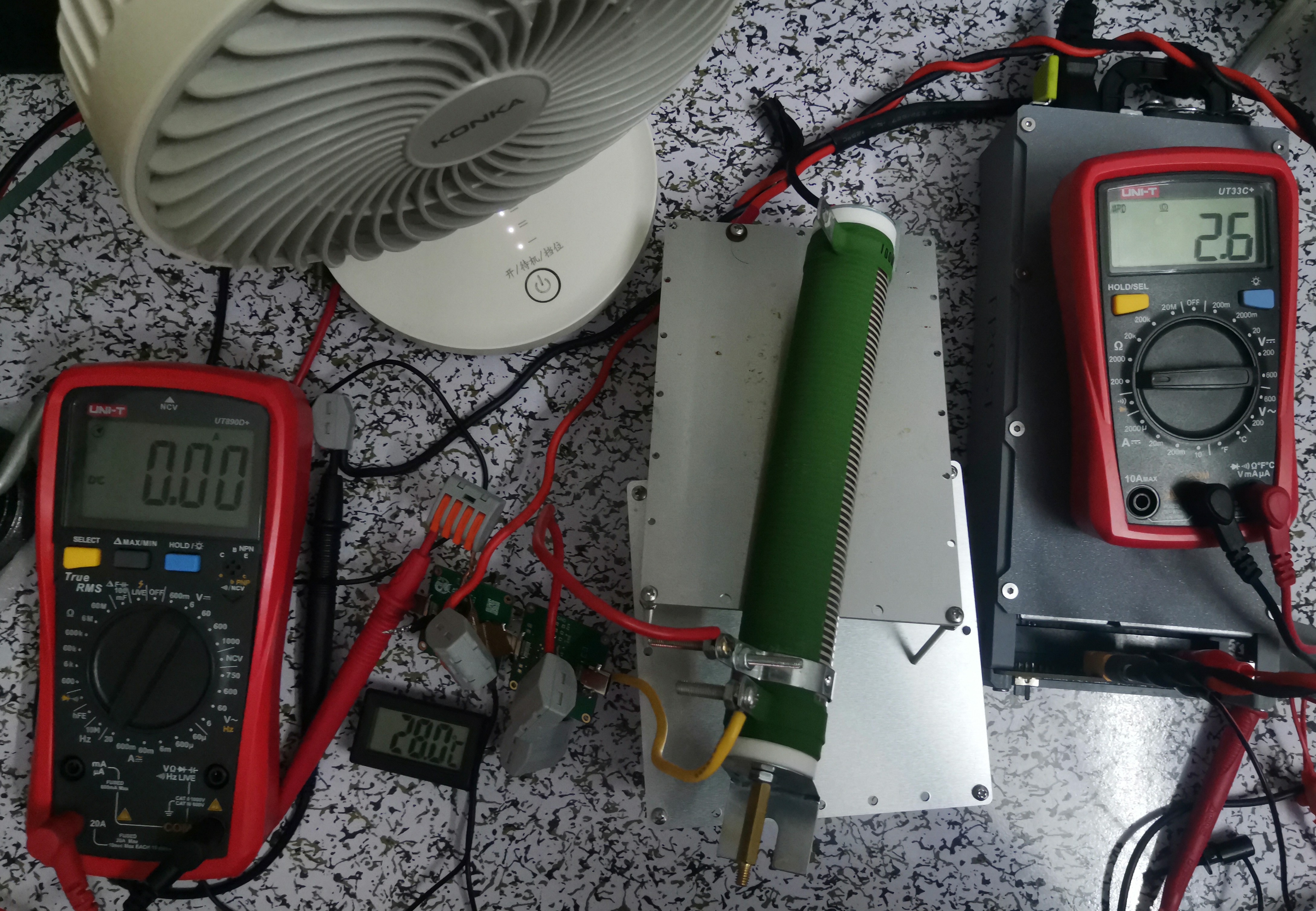
overcurrent capability test
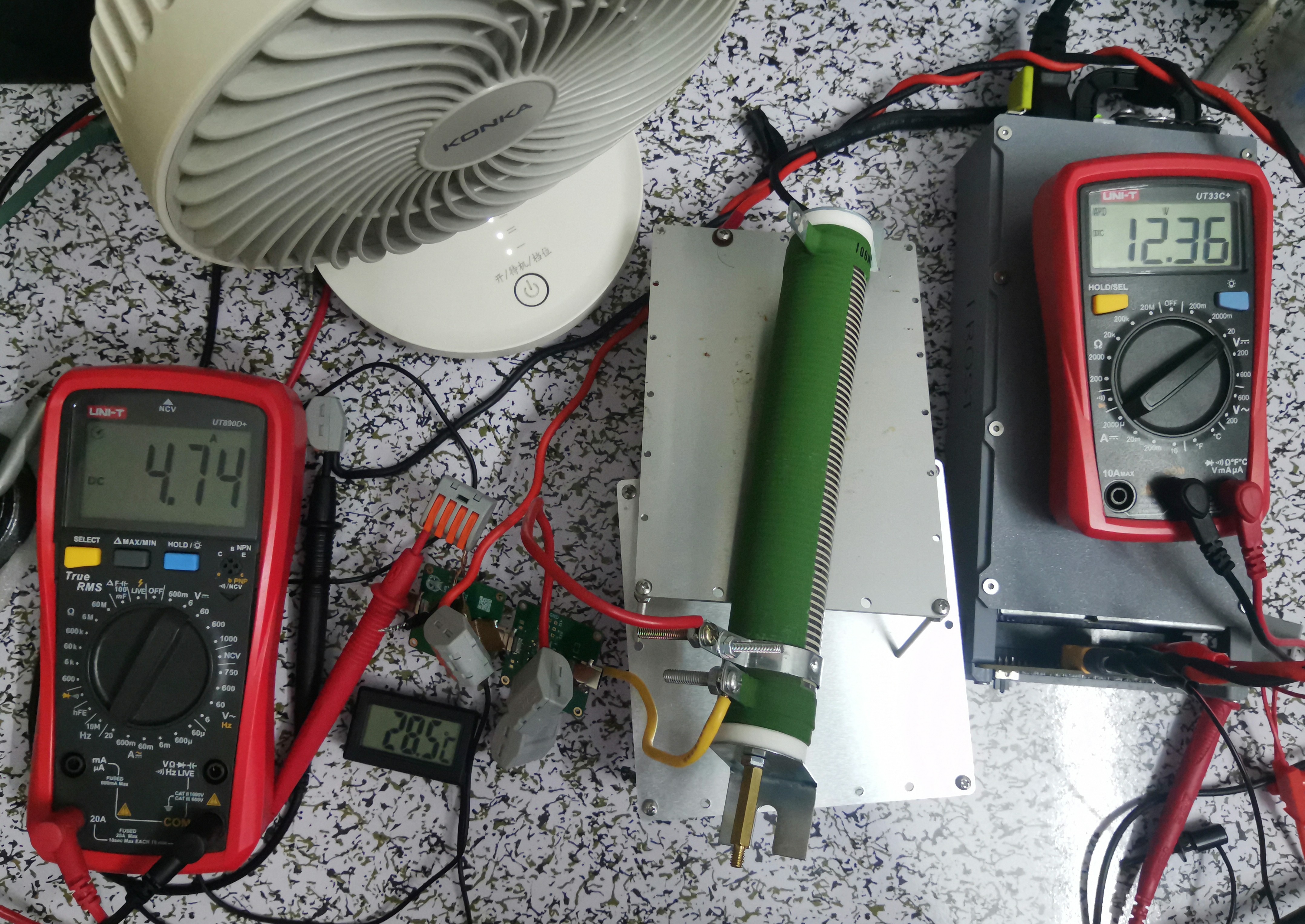
used a 12V power supply (450W) with a power resistor as the load. The target current was 5A, but after connecting all cables, the measured resistance was 2.6Ω, and the resistance increased after heating, ultimately preventing the current from reaching 5A. The
overcurrent capability was judged based on the temperature sensor. Since the air conditioner was just starting to cool during the test, the ambient temperature can be estimated at 26.5-27.5℃. The test duration was a few minutes (the load was a bit too much, the total resistance was too high, only a small portion heated up, and the heat dissipation was poor). It's also possible that airflow blew onto the adapter board, but the final temperature rise was not high. Conservatively, it can be considered to support PD for a short period. 100W current;
during testing, the wire was directly inserted into the adapter board pads. It's uncertain how the overcurrent capacity would be if a header pin and jumper cap were used.
The following image shows the resistance before power-on:
The following image shows the current during testing:
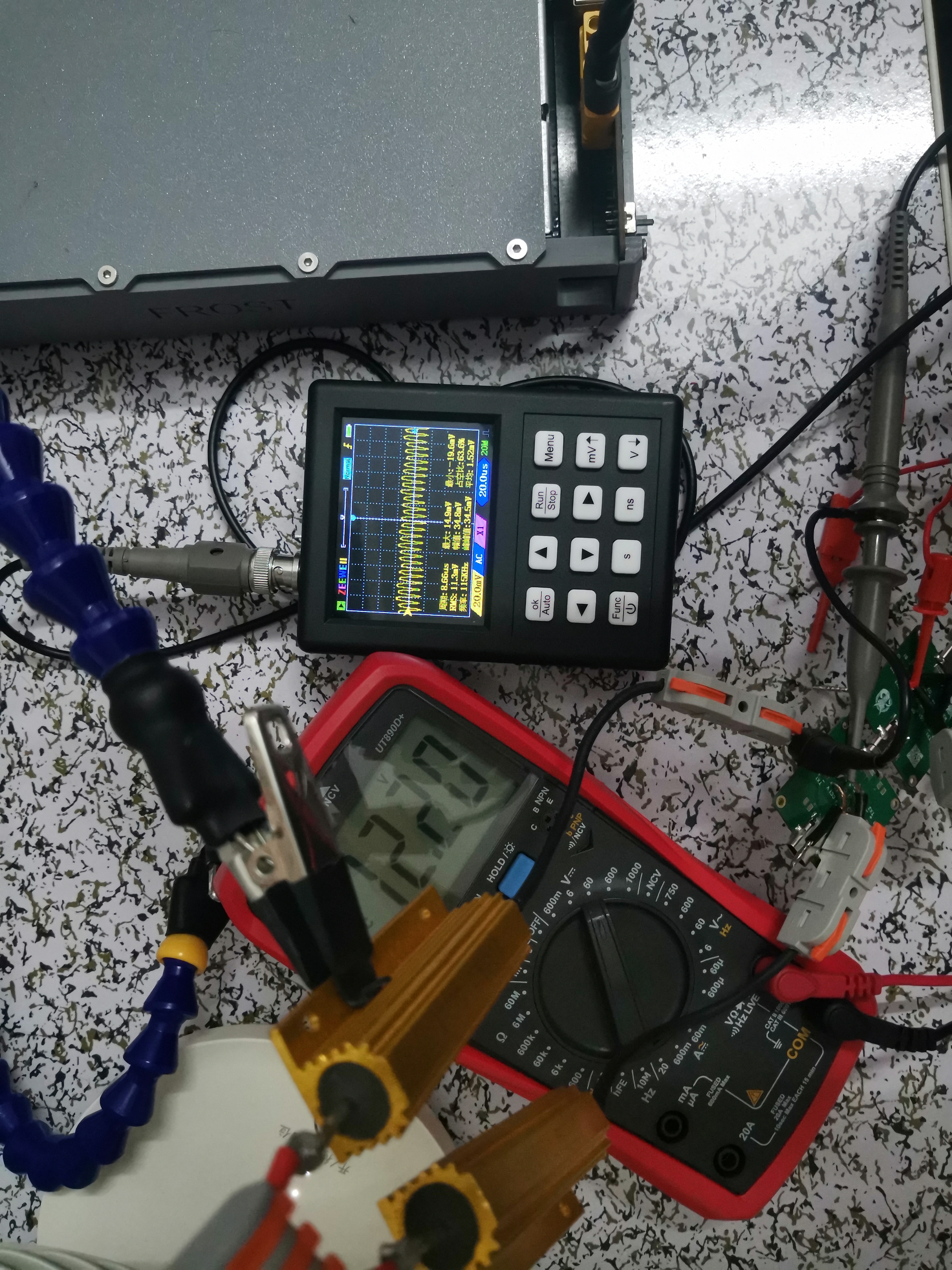
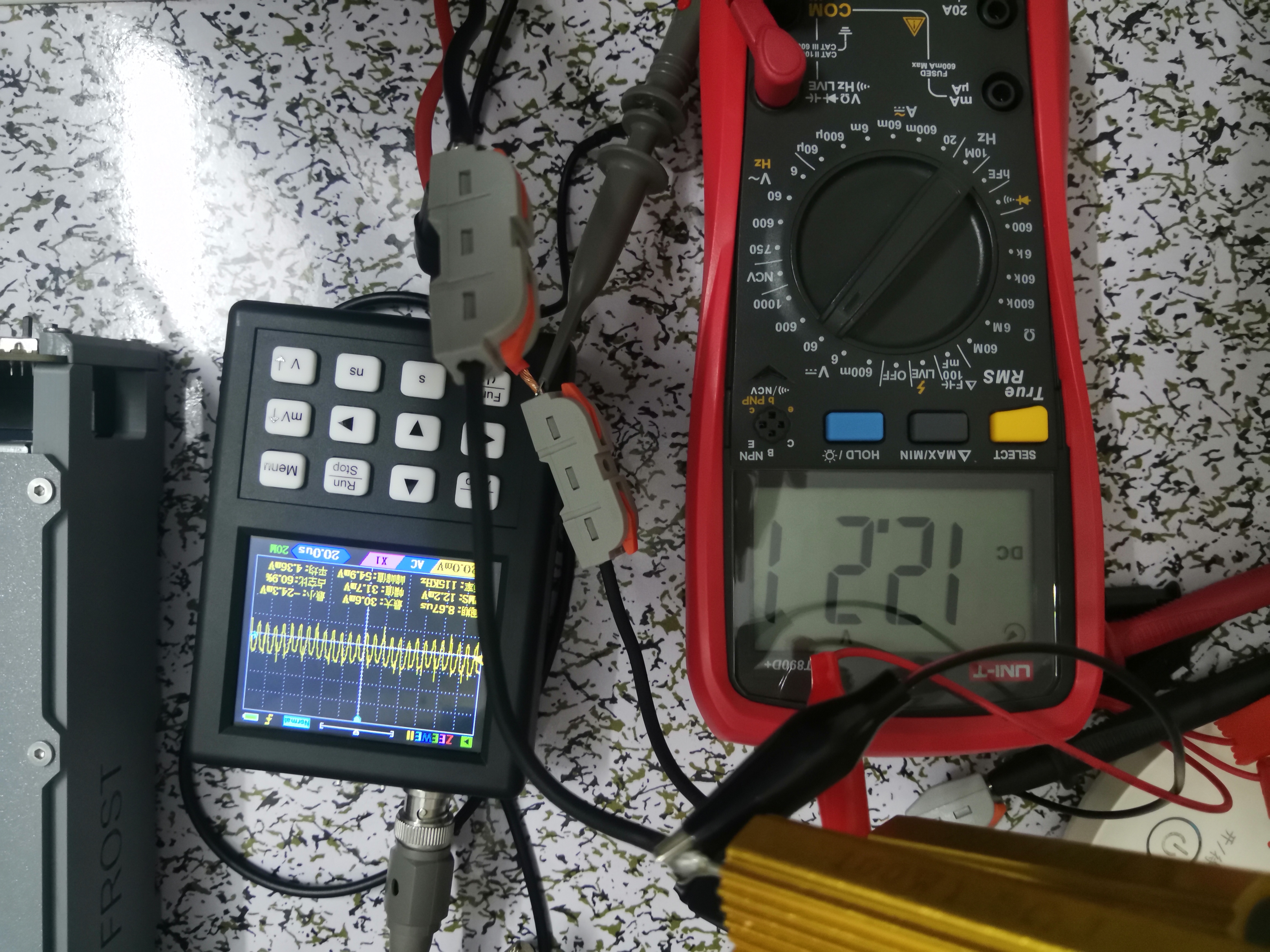
The ripple test
still used the above power supply, with two 1.5Ω resistors in parallel. The actual current was less than 4A. The ripple was tested through the adapter board and directly connected. The oscilloscope connection was not standard, so the results are for reference only. The final minimum peak-to-peak values were similar, while the maximum peak-to-peak value was slightly lower after connecting the adapter board.
It's an RC filter; my excellent PCB design has its own RC filter (not really)
. The following image shows the ripple using the adapter board:
The following image shows the ripple of the direct connection:
PDF_TypeC Interface Female to Male Adapter Board 24pin.zip
Altium Type-C female to male adapter board 24pin.zip
PADS_TypeC interface female to male adapter board 24pin.zip
BOM_TypeC interface female to male adapter board 24pin.xlsx
92109
electronic


 京公网安备 11010802033920号

 AZ951-1CM-24DE


