The problem requires
an energy consumption analysis system based on the INA219 sensor and a microcontroller. Common energy consumption
analysis
methods are mainly divided into two types: model-based energy consumption analysis and measurement-based energy consumption analysis. The former refers to establishing a power model of the system under test to estimate its energy consumption level for analysis; the latter uses sensors or power meters to measure the operating load circuit to obtain actual physical signals and values, thus offering higher accuracy. This paper designs a system that uses the INA219 sensor to sample energy consumption data and analyzes it using an STM32 microcontroller, suitable for load circuits powered by various interfaces. The system can be functionally divided into an energy consumption acquisition module, an energy consumption analysis module, a communication module, and a screen display module. The energy consumption acquisition module measures the physical signals of the load circuit and converts them into calculable data. This module uses the INA219, a zero-drift bidirectional current/power sensor with an I2C interface. The energy consumption analysis module uses a high-performance STM32 series microcontroller to receive and analyze the acquired data. The communication module uses software to simulate I2C communication, allowing the microcontroller to configure the INA219 and receive sampled data. The screen display module presents sampling data, analysis results, energy consumption line graphs, and abnormal alarms to the user via a TFTLCD screen.
Overall Design Scheme Block Diagram

Schematic Design Description:
The energy consumption analysis module in this system uses an STM32F103ZET6, directly adopting the Zhengdian Atom's Warship development board, thus eliminating the need for PCB design. The energy consumption sampling module requires the integration of INA219 sensors and PCIe Ex1 gold fingers and slots, therefore requiring the design of an adapter card schematic and PCB.
The most important components of the adapter card are the three INA219 sensors, which measure the power of +12V, +3.3V, and +3.3Vaux respectively. Since the PCIe power supply protocol includes five +12V channels, totaling a maximum current of 5.5A, I calculated using formulas that a 50mΩ shunt resistor should be configured for the INA219 measuring the +12V circuit, and 100mΩ shunt resistors should be configured for the other two INA219 sensors. In addition, by obtaining the PCIe x1 gold finger package from the open-source platform, and combining it with the PCIe slot and pin socket packages provided internally by EDA, the schematic diagram of the adapter card can be created.

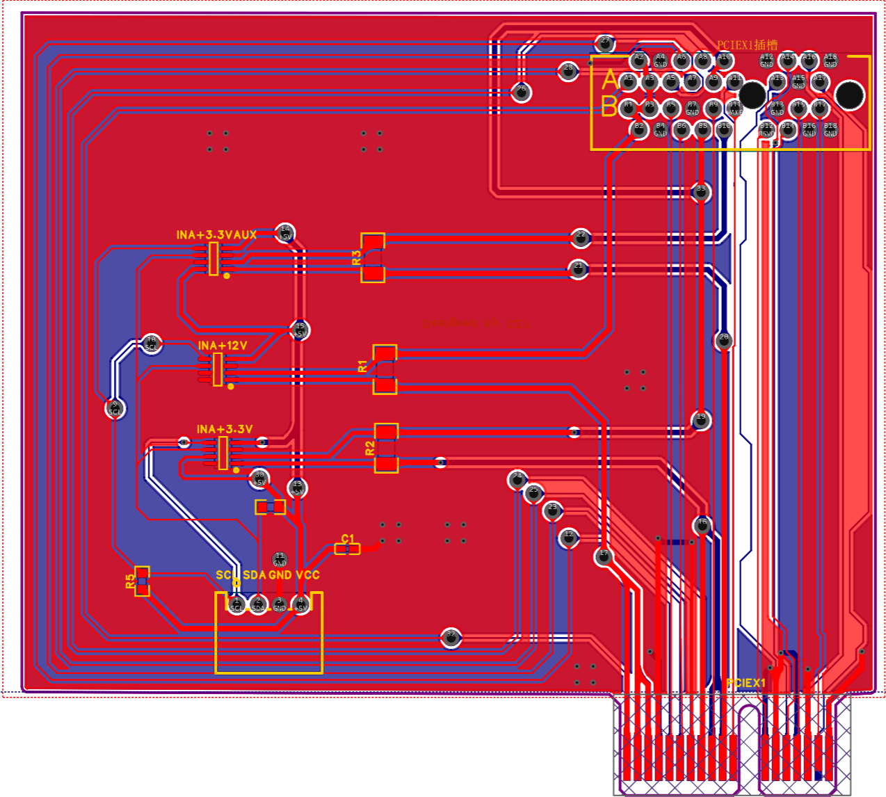
PCB Design Instructions :
After completing the schematic design, directly generate the PCB file in LCSC EDA after DRC check, and then perform layout and routing according to the rules. Pay attention to the principle of similarity and proximity during layout, and pay particular attention to the differential pair design rules (there are multiple differential pairs in the PCIe protocol), including the length difference of differential pairs, line width, etc. After layout, routing, and copper pouring, perform DRC check again. Once it is correct, place an order for prototyping. LCSC EDA projects can be prototyped free of charge by LCSC!
Software Description:
According to the system block diagram, the software mainly implements four functions: reading sampled data, I2C communication between the adapter card and the microcontroller, calculating energy consumption data (including average power, extreme values, and standard deviation), and displaying text and line graph statistics on the screen. Due to the large number of code files, they will not be described in detail here. If you happen to see this and need detailed project code, you can directly download the attached .zip file. The software code files, hardware project files, PCB layout files, and BOM (Bill of Materials) are all included.
A physical demonstration
is attached with a picture of the completed board:

In actual operation, a PCIe x1 load needs to be inserted into the adapter card (this graduation project uses a wireless network card). The PCIe gold fingers of the adapter card are inserted into the slot in the chassis. After powering on, the network card can start normally and collect power consumption data.
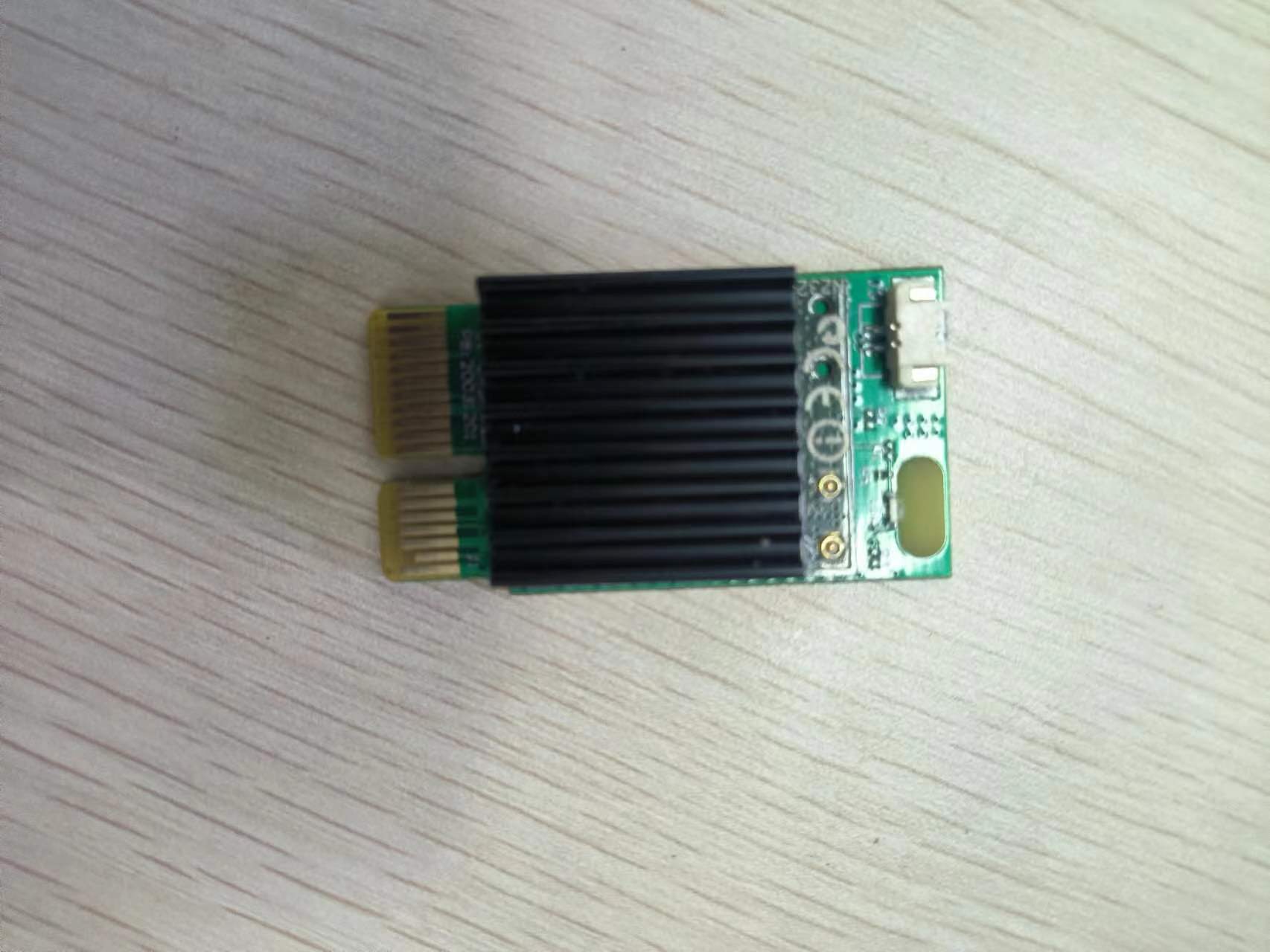
Then, connect the four pins (VCC, GND, SDA, SCL) on the adapter card to the +5V, GND, and I2C protocol SDA and SCL pins defined on the STM32 microcontroller development board (using software-simulated I2C, therefore, pins GPIOA5 and 6 of the microcontroller need to be connected). Burn the project code into the microcontroller, and you will see the three interfaces displayed on the development board's LCD screen. Below are images showing the adapter card in operation:

Demonstration videos
of the system's three display interfaces and the abnormal alarm interface have been uploaded as attachments. Please feel free to watch!
Other attachments are
not yet uploaded
. In conclusion
, life often takes unexpected turns. After graduation, I will be working in a marketing position, but I still have a passion for technology and look forward to one day leveraging it to advance my career. Today, I'm posting my graduation project here, partly because I referenced open-source projects while writing it, and partly to acknowledge my four years of university study, constantly reminding myself that I am capable of independently designing hardware and software. In my future career, I should work even harder to learn and understand technology, and never abandon it. Never forget where you came from, and start anew! As I write this, I feel a mix of emotions. I conclude with this and share it with you all.


 京公网安备 11010802033920号

 1002-004-2001-P008


