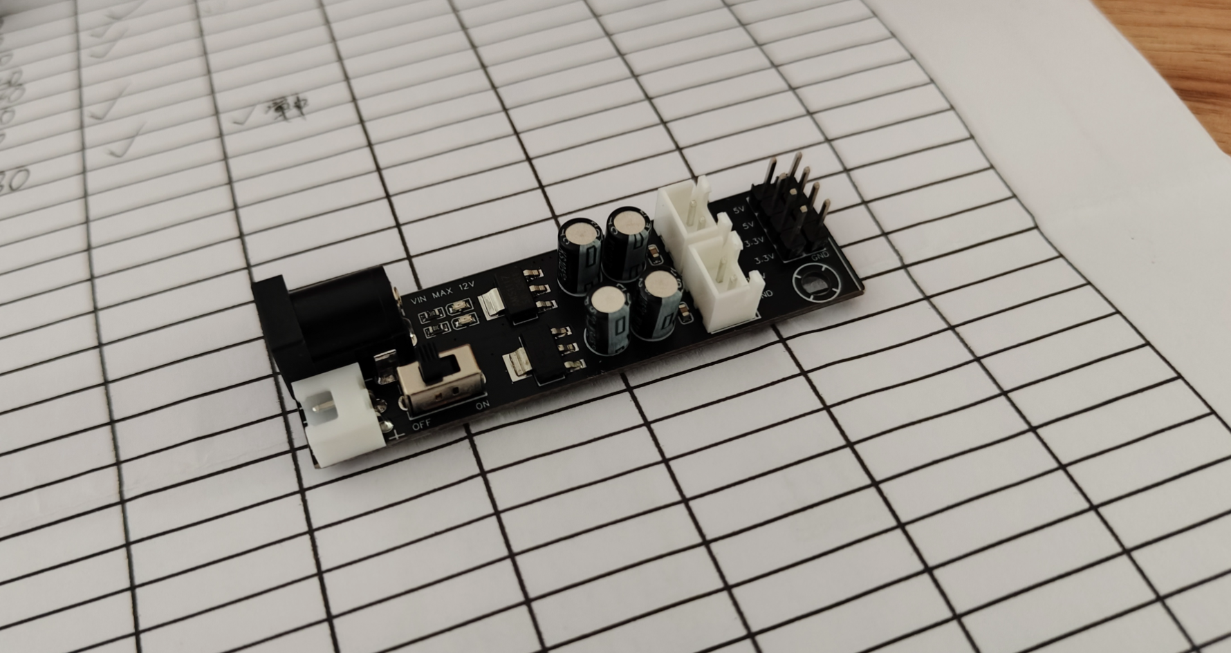
The power module, based on the AMS1117, features dual 5V and 3.3V voltage outputs.
PDF_POWER-AMS1117-MODE.zip
Altium_POWER-AMS1117-MODE.zip
PADS_POWER-AMS1117-MODE.zip
BOM_POWER-AMS1117-MODE.xlsx
93797
STC32G12k128
This project aims to design and implement a learning and development board based on the STC32G12K128 microcontroller, providing embedded systems learners and developers with a comprehensive and easy-to-use platform. The development board integrates a USB-TTL download circuit, a power-off reset circuit, and a reference voltage.
This project aims to design and implement a learning and development board based on the STC32G12K128 microcontroller, providing a comprehensive and easy-to-use platform for embedded system learners and developers. The development board integrates a USB-TTL download circuit, a power-off reset circuit, a reference voltage source, an LED indicator circuit, and an external FLASH storage circuit, providing users with a powerful hardware environment suitable for the development and testing of various embedded applications.
Hardware Design:
USB-TTL Download Circuit The
USB-TTL download circuit is one of the core functions of the development board, using the CH340 chip as a USB-to-TTL signal converter. This design allows users to easily upload firmware to the microcontroller via a standard USB interface, greatly simplifying the programming process and improving development efficiency. The CH340 chip supports drivers for multiple operating systems, ensuring good compatibility.
Power-Off Reset Circuit
The power-off reset circuit ensures reliable system reset after a power outage. When power is reconnected, the reset circuit detects a voltage rise and triggers a reset pulse, ensuring the microcontroller starts execution from a known state, avoiding potential system failures or data corruption. A
reference voltage
source is integrated on the development board to ensure the stable operation of the microcontroller and other sensitive circuits. This circuit provides a stable reference voltage, which is crucial for AD/DA conversion, power monitoring, and other applications requiring precise voltage reference. An
LED
indicator circuit visually displays the development board's status, such as power status and operating mode. This is very useful for debugging and monitoring system operation, especially in situations without a display, where LEDs can serve as a quick diagnostic tool. An external FLASH
memory
circuit provides additional storage space for application code and other data. This is particularly important for applications requiring significant storage resources, such as complex algorithm processing, data logging, and playback. For
software
development, the development board supports multiple development environments, including but not limited to Keil, IAR, and STM32CubeIDE. Developers can use these toolchains to write and debug code to control the STC32G12K128 microcontroller. Furthermore, sample programs are pre-installed on the development board to help beginners get started quickly, including basic GPIO control, timer configuration, and serial communication.
Application Cases:
This development board is suitable for various application scenarios, including but not limited to:
Internet of Things (IoT) Device Development: Utilizing the low-power characteristics of microcontrollers, it can be used to design smart home devices, industrial sensor networks, etc.
Automation Control Systems: Applicable to factory automation, agricultural automation, and other fields, enabling precise control and remote monitoring.
Teaching and Research: As a teaching tool, it helps students understand the working principles of embedded systems; at the same time, it provides researchers with a flexible hardware platform for exploring and verifying new technologies.
Testing and Verification:
After the design is completed, the development board must undergo a series of rigorous tests to ensure its performance and reliability. This includes power stability testing, signal integrity testing, thermal testing, functional testing, and compatibility testing. Test results should be recorded in detail, and any problems found should be resolved promptly to achieve the design goals.
PDF_STC32G12k128.zip
Altium_STC32G12k128.zip
PADS_STC32G12k128.zip
BOM_STC32G12k128.xlsx
93798
Lazy person switch on/off lights
Lights can be remotely switched on and off via infrared remote control and voice recognition.
Lights can be remotely switched on and off via infrared remote control and voice recognition.
a79e5221301d2a627ec545231a8fcdcd.mp4
50f217d2063b31e56660e5dfc17c004.jpg
PDF_Lazy Person's Light Switch.zip
Altium_Lazy Person's Light Switch.zip
PADS_Lazy Person's Light Switch.zip
BOM_Lazy Person's Light Switch.xlsx
93799
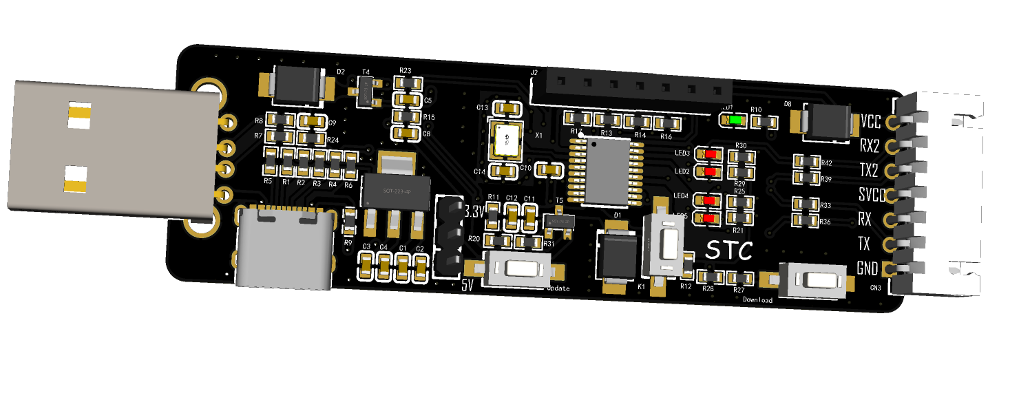
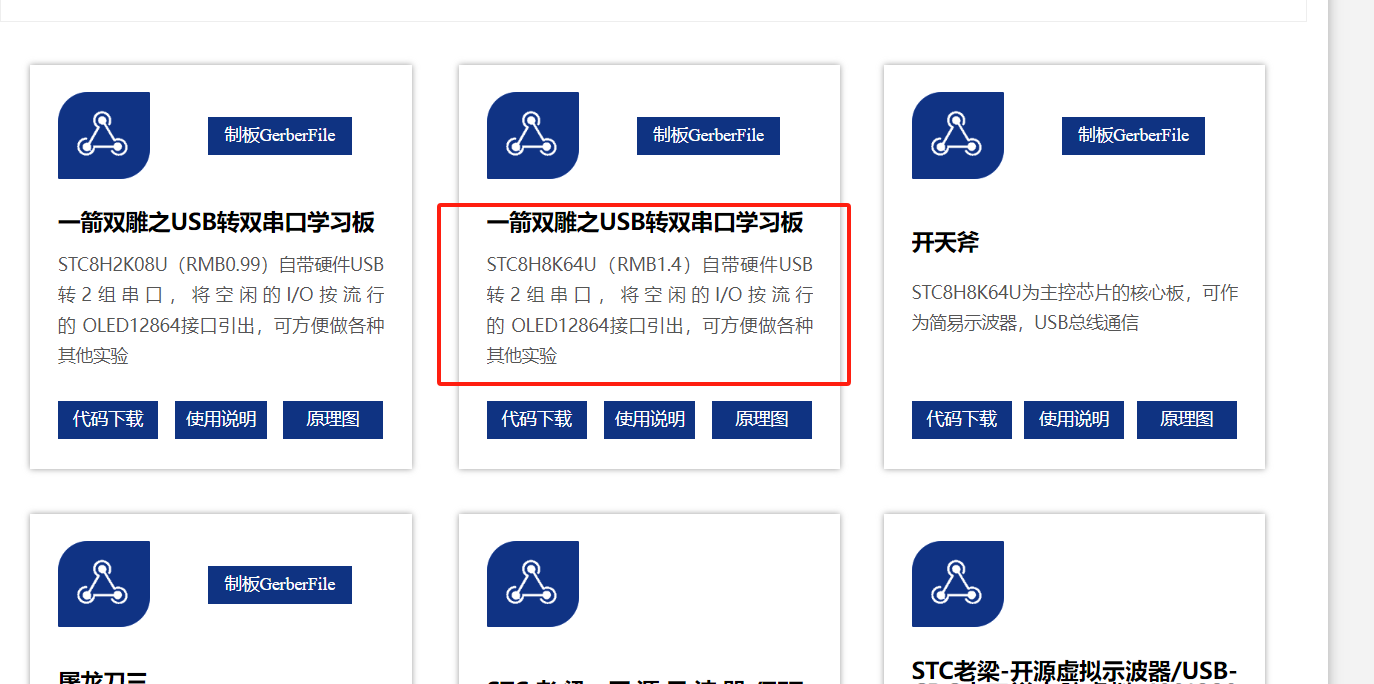
USB to Dual Serial Port Learning Board
This project is a replica of the STC USB to dual serial port learning board, a product of STC's expertise in domestic chip manufacturing, and is designed based on the official schematic. The chip used is the STC8H8K64U (RMB 1.4).
This project is a replica of the STC USB to dual serial port learning board, a product of STC's expertise in domestic chip manufacturing, and is designed based on the official schematic. The chip used is the STC8H8K64U (RMB 1.4).
Verification complete.
Front view of the board
! [Front.jpg]

Back view of the board
! [Back.jpg]

3D view of the front of the board
! [Image.png]
3D view of the back of the board
! [Image.png]

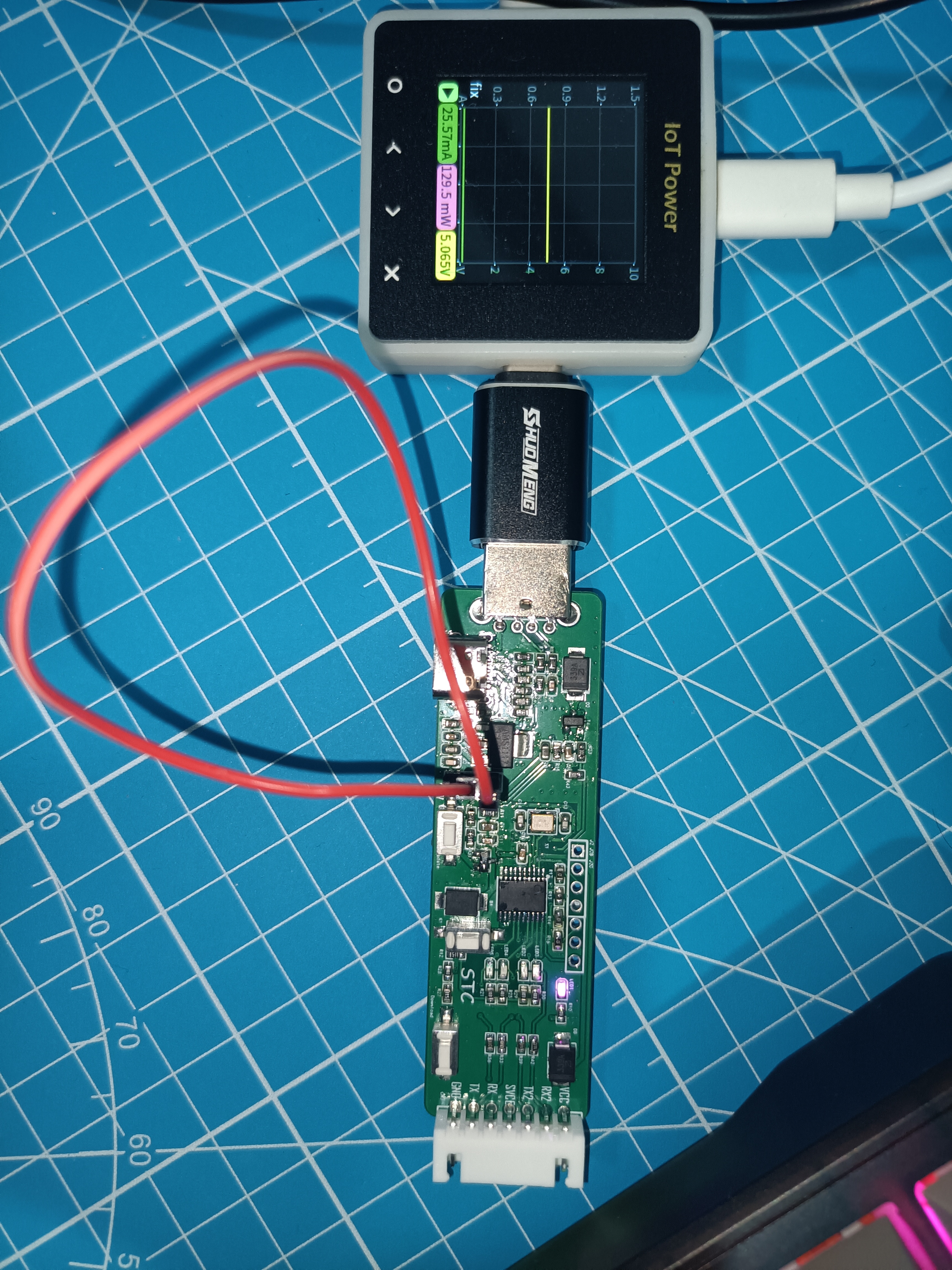
Power-on effect of the board (Please ignore the fact that I didn't have jumper caps, so I used a very long DuPont wire. Also, a quick look at the power consumption, which is still very low)
. [USB port.jpg]
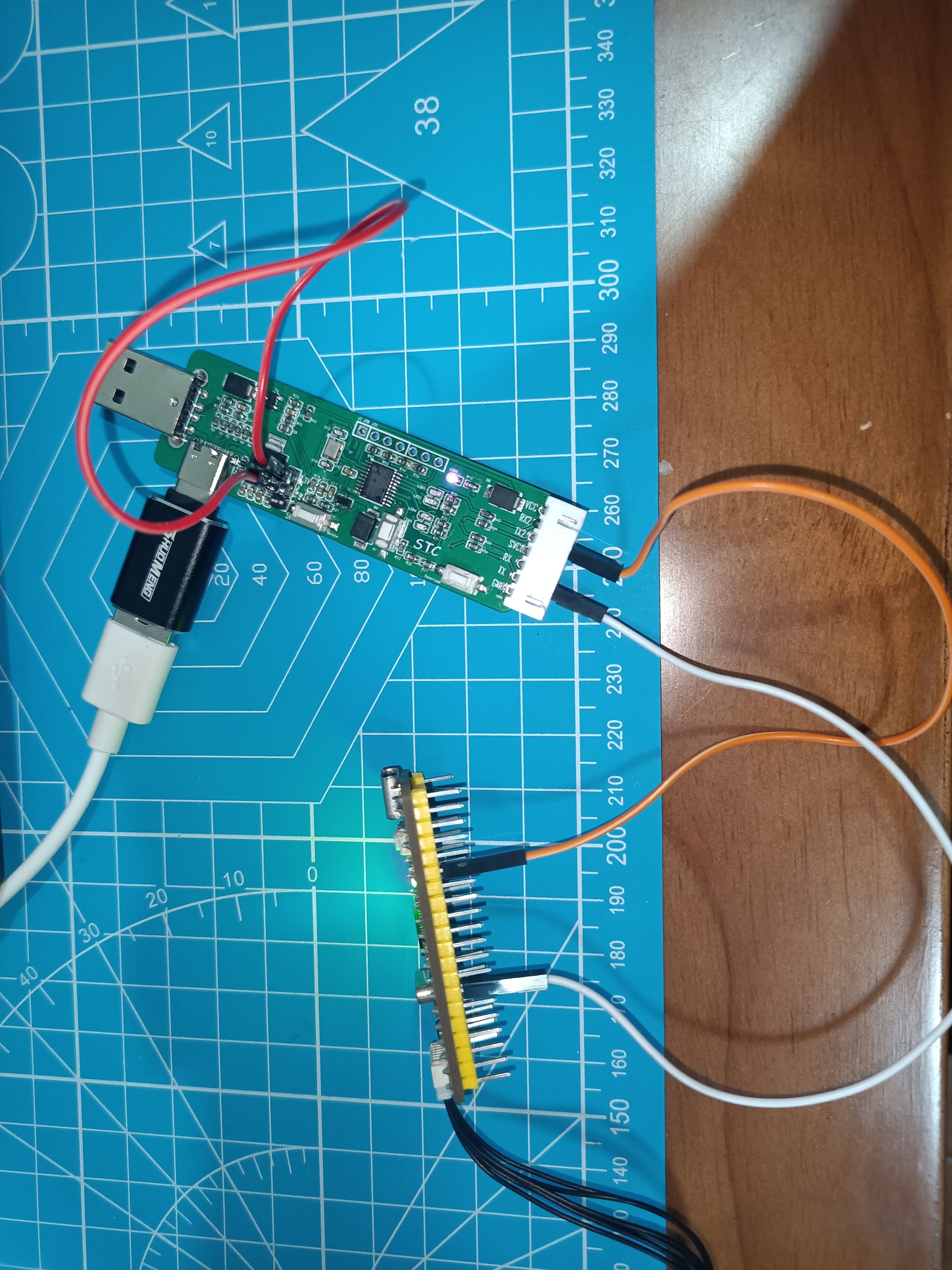
Wiring diagram of the board. Here I used a homemade small board, simultaneously sending data via serial port 1 at a baud rate of 115200 and serial port 2 at a baud rate of 460800
! [Running.jpg]
Host computer effect (This is using STC-ISP software, opening different serial port assistant pages to view the simultaneous transmission of data via both serial ports, as shown in the image, excellent!)
. [Function.png]

Official data link: https://www.stcai.com/hxgnsyb. As shown in the
image
, you can obtain the official code, instructions, schematics, and official Gerber PCB design files. It's undeniable that the official website is much more user-friendly now, making it easier to access resources for free.
This solution uses the STC8H8K64U (RMB 1.4), a very competitively priced chip. Replicating this project offers excellent value for money; for the price of a beverage, you get a powerful tool that meets both development needs and learning purposes.
The official documentation provides a detailed user guide, demonstrating how to create a USB CDC to dual serial port adapter using this tool. This adapter can be used as a serial programmer and connected to an OLED screen for OLED display. Why not get started? Replicating this project is quite fun and can be used to learn about the latest USB-51. Let's get started!
PDF_USB to Dual Serial Port Learning Board.zip
Altium_USB to Dual Serial Port Learning Board.zip
PADS_USB to Dual Serial Port Learning Board.zip
BOM_USB to Dual Serial Port Learning Board.xlsx
93800
ESP-12F_AdapterBoard
The ESP-12F adapter board is compatible with ESP12-E, ESP-12F, ESP-12S and other modules.
The ESP-12F adapter board is compatible with ESP12-E, ESP-12F, ESP-12S, and other modules. All pins are exposed, including power and GPIO indicator lights for easy debugging. A button is provided for GPIO0; pressing it grounds the device for easy program downloading and burning.
PDF_ESP-12F_AdapterBoard.zip
Altium_ESP-12F_AdapterBoard.zip
PADS_ESP-12F_AdapterBoard.zip
BOM_ESP-12F_AdapterBoard.xlsx
93802
STM32 Minimum System Board
The functions of the designed STM32F10C8T6 minimum core board have been verified. The onboard CH340N can be used as a USB to TTL serial port downloader, and STlink can also be used to download programs. In addition, I have added an OLED screen to the board to facilitate code debugging.
The designed STM32F10C8T6 minimum core board has been verified to achieve all functions. The onboard CH340N is used as a USB to TTL serial port downloader, and STlink can also be used to download programs. In addition, I have added an OLED screen to the board for easy code debugging. The step-down circuit uses the common AMS117 chip to reduce the 5V VBUS voltage of the Type-C to 3.3V for microcontroller power supply.
OLED display.jpg
Back view.jpg
Flowing Lights.mp4
Button Display.mp4
Product demonstration video 1.mp4
PDF_STM32 Minimum System Board.zip
Altium_STM32 Minimum System Board.zip
PADS_STM32 Minimum System Board.zip
BOM_STM32 Minimum System Board.xlsx
93803
WeChat Mini Program Remote Touchscreen Clicker
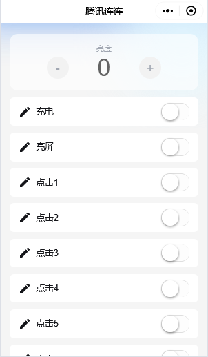
Based on the ESP12F main controller, MQTT connects to the Tencent Cloud platform, and the phone screen can be remotely clicked through the Tencent Lianlian mini program.
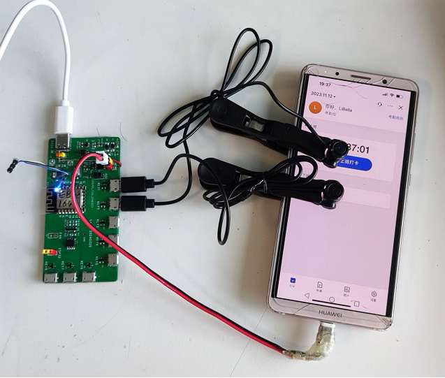
Project Introduction (Physical Image ): Main
Control Chip: ESP12F;
Main Application Scenarios: Remote Check-in
Function Introduction:
The ESP12F connects to the Tencent Cloud IoT platform via Wi-Fi and can be remotely controlled via the Tencent Lianlian WeChat mini-program.
The control board can individually control up to 8 click heads, which can be controlled by eight buttons on the mini-program to click the screen once.
It features screen brightness detection using a photoresistor attached to the phone screen.
It also has a timed phone charging function. Soldering Notes:
The control board was provided free of charge by JLCPCB.
The BOM (Bill of Materials) is provided in the attached table.
The 16-pin Type-C female connector does not need to be soldered. When using a 5V2A charger via a Type-C cable, I found the phone charging speed to be particularly slow; when using a 5V2A DC power supply via H1, the charging speed was not as slow.
The three 4148 diodes on the back do not need to be soldered .
The AO4805 and related circuit components do not need to be soldered.
The H4 connector is the phone's charging interface and is also used to power on and off the phone to turn on the screen.
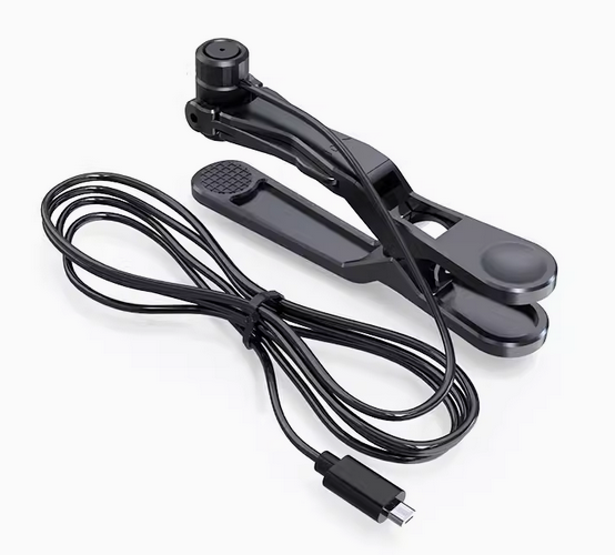
The click heads
were purchased as finished products from Taobao. Searching for "clicker" will lead you to a purchase package with the main unit shown in the image below.
You buy a package containing as many click heads as you need to click on the screen. All click heads share a single click signal.
For details on the click heads, please search for the patent "CN216772390U - An Electronic Slider and System," which contains detailed circuit diagrams and instructions.

The click head looks like the image below, with a Micro USB plug and a clip to attach to the screen.
Tencent Lianlian Mini Program Interface:
Tencent Cloud IoT Development Platform
User Guide Reference: In the link below, when importing the object model, use the josn file in the attachment. Ignore the network configuration steps.
Step-by-step tutorial – ESP32 MQTT connection to Tencent Cloud IoT Platform and OTA firmware upgrade - ThingsKit
ESP32: Creating IoT devices in Tencent Cloud IoT console (using Tencent Lianlian to control ESP32) _eso32cam Tencent Cloud IoT - CSDN Blog
ESP12F program:
See the attached ino file.
Notes:
Replace WIFI_SSID and WIFI_PASSWORD in lines 9 and 10 with your own Wi-Fi username and password.
Replace DeviceName and ProduceId in lines 12 and 13 with the device name and product ID set in the IoT platform.
Replace MQTT_USERNAME and MQTT_PASSWORD in lines 14 and 15 with the username and password used for device connection in the IoT platform.
Tencent Cloud IoT Object Model.json
ESP12F-Login.ino
BOM_ESP12F-LOGIN_ESP12F-LOGIN_2024-07-03.xlsx
PDF_WeChat Mini Program Remote Touchscreen Clicker.zip
Altium_WeChat Mini Program Remote Touchscreen Clicker.zip
PADS_WeChat Mini Program Remote Touchscreen Clicker.zip
BOM_WeChat Mini Program Remote Touchscreen Clicker.xlsx
93807
#Training Camp# Simple Digital Oscilloscope
Building a Simple Digital Oscilloscope: A Replicated Tutorial from the Bootcamp
Making a Simple Digital Oscilloscope
PDF_#Training Camp# Simple Digital Oscilloscope.zip
Altium_#Training Camp# Simple Digital Oscilloscope.zip
PADS_#Training Camp# Simple Digital Oscilloscope.zip
BOM_#Training Camp#Simple Digital Oscilloscope.xlsx
93809
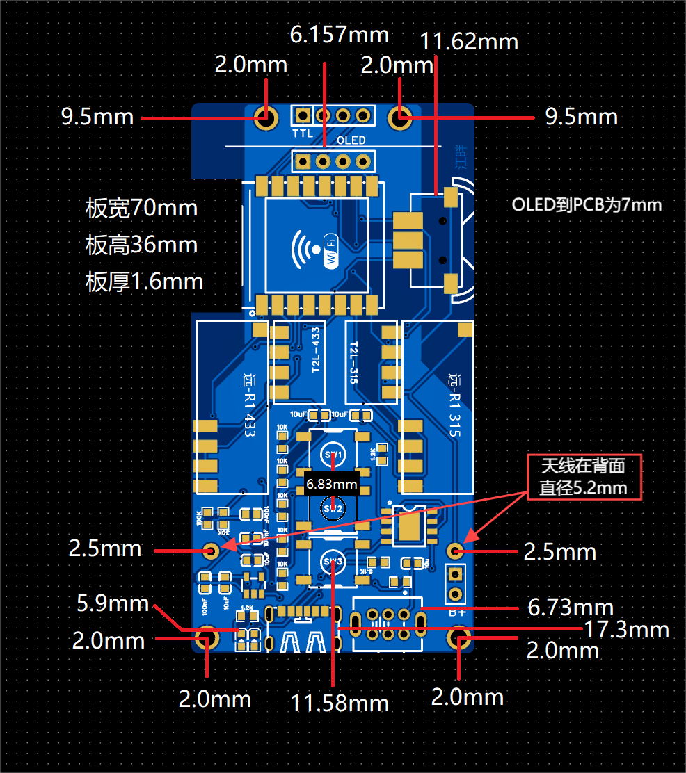
RF Manager (Telescopic Antenna Version)
The RF transceiver with a trolley antenna is here! This 315/433MHz non-rolling code RF transceiver, compared to SMA antennas, features a trolley design for easier storage and a wider coverage area with its external antenna. (Transmit/receive functionality verified)
First, let's look at the actual product images. Here's
a simplified shell, finished
PCB, and appearance. It features a
large-capacity 600mAh 502060 battery

and a telescopic antenna. The antenna selection is shown in the image below. For antenna testing results, please refer to YS-tao's version 1.3. The No. 5 antenna
screw uses M2*12.

Acknowledgements: The PCB was provided by JLCPCB platform; their open-source approach is truly impressive.
Due to
my limited 3D modeling skills, I only created a simple, functional shell. If any expert is willing to design a more aesthetically pleasing shell (such as an ellipse or irregular shape), please submit your design after receiving the PCB. I can print the shell for you. The image below shows the detailed PCB dimensions; you can design your shell based on these dimensions.
Gerber RF Butler Pull-up Rod PCB Design Files.zip
3DShell_RF Butler Pull Rod_Front Shell.stl
3DShell_RF Butler Pull-up Back Cover.stl
v2.9.a_Battery Display Firmware.bin
BOM_Bill of Materials.csv
PDF_RF Manager (Track Antenna Edition).zip
Altium_RF Manager (Lever Antenna Version).zip
PADS_RF Manager (Track Antenna Version).zip
BOM_RF Manager (Telescopic Antenna Version).xlsx
93811
USB ammeter
USB ammeter 5V for personal study
1. Function Introduction:
A USB ammeter capable of measuring approximately 5V.
2. Open Source License:
GPL 3.0
3. Main Controller:
Nationwide N32G430 series chip
4. Physical Product Image:

5. PCB Layout:
PDF_USB Ammeter.zip
Altium_USB Ammeter.zip
PADS_USB Ammeter.zip
BOM_USB Ammeter.xlsx
93812
electronic


 京公网安备 11010802033920号

 M220024GP.L.MJ


