Most common car designs currently use small 5V motors with very low power, primarily intended for learning or hobby use, and lack practicality. For everyday use, such as transporting goods or as a patrol car, the motor power needs to be increased. This requires motors with voltages above 12V and power exceeding 20W. There are two options: brushed and brushless motors. To drive a high-power brushed motor for commutation and speed control, an H-bridge is needed. Taking advantage of this event, I'm finally realizing my long-held idea of building a car. I'm using an STC8h4k64TL as the main controller, driving two H-bridges to control the DC brushed motors for speed regulation. Since I'm new to this chip and not yet familiar with some of its performance characteristics, I'm using a half-bridge driver chip, the EG2104, for safety (I'm also unfamiliar with the EG2104 and encountered some problems along the way). A PS2 is used for remote control. The 2.4G controller

has a familiar design reminiscent of my younger days. It comes with a 2.4G receiver and has a range of approximately 10 meters. During testing, the data transmission in joystick mode was sometimes unstable and intermittent, so a button mode was used instead. Up, down, left, and right buttons control direction; left and right differential speed controls steering; the △ button performs PWM auto-increase acceleration; and the × button performs PWM auto-decrease deceleration. Each direction has a corresponding indicator light,
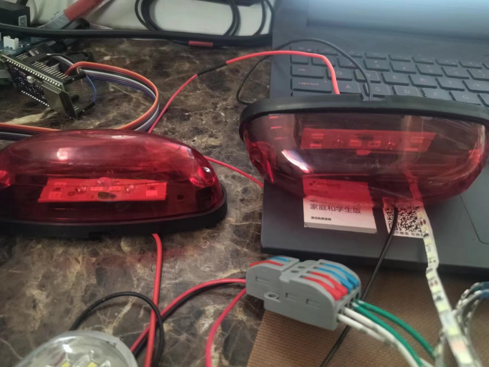
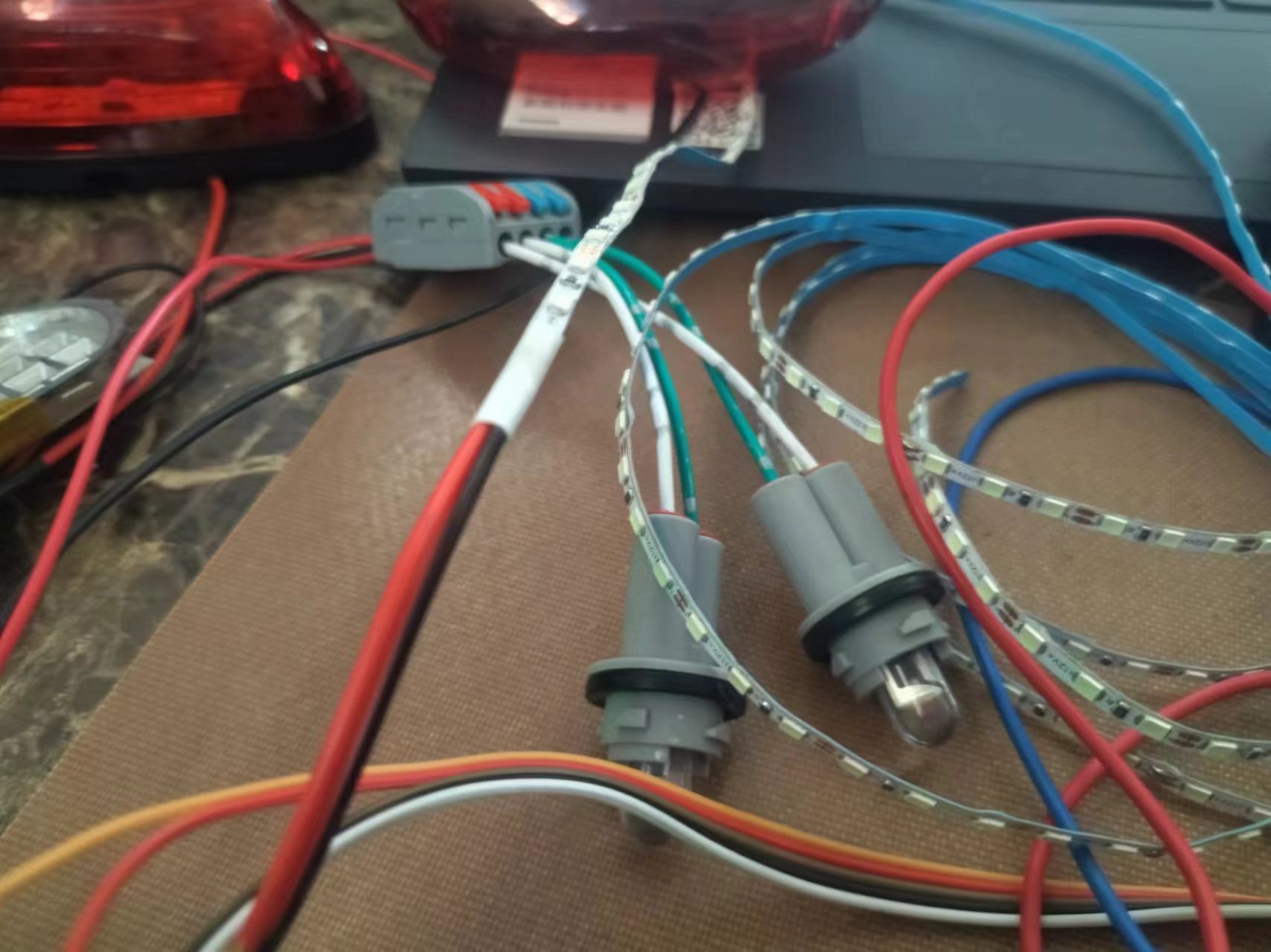
including two reverse indicator lights. These lights operate on 12V and are driven by a ULN2003 driver. Note that the maximum current should not exceed 500mA. A ring of ambient lights surrounds the reverse indicator lights, which can be used for decoration around the car. Due to the high current draw, a separate MOS driver is used, with a current exceeding 1A. The circuit includes an NTC 10K connector for measuring battery or motor temperature. A resistor divider is used to measure the power supply voltage, which can be used for undervoltage warnings. Both H-bridges are grounded using 0.1R 2512 alloy resistors for current acquisition and overcurrent protection to prevent overload. The PCB design began on June 19th and debugging was completed on the 29th. During this time, we encountered basic issues like burning out the main controller and damaging the driver chip. While programming, I noticed the MCU had four pairs of complementary outputs (PN), so I used 1CHANNEL and 3CHANNEL to control four EG2104s respectively. However, during testing, the motors exhibited abnormal behavior. Sometimes they would move briefly after receiving a signal, and sometimes they would only move after quickly switching between forward and backward directions. Individual forward and backward movements were impossible. I reviewed the EG2104 and MCU manuals multiple times without finding the cause. Finally, after studying the bootstrap principle of the H-bridge, I realized that this solution couldn't provide 100% PWM. Without PWM, simply using a high level wouldn't drive the upper transistor properly. This was a significant pitfall, as some online sources confidently claimed direct drive was possible, but the truth table didn't reveal the problem. Furthermore, directly measuring the driver chip with a multimeter was difficult to determine if it was functioning correctly, as the quality of products from Taobao is often unreliable. One of the four chips was faulty, and the problem was finally identified using an oscilloscope. The biggest challenge was that while the program logic was correct, it simply wouldn't work properly, even though the hardware was confirmed to be fine. The program was modified countless times. Finally, I checked Mr. Liang's video on driving a three-phase brushless motor on the STC official forum and downloaded the corresponding program, but still couldn't find a reasonable explanation. Driving this type of half-bridge chip requires one PN channel to be PWM and the other to be set to low level, but the measurement results matched the program, yet it still wouldn't drive properly. Finally, I discovered that the motor could run when rapidly switching directions, possibly due to the Miller platform. Based on this observation, I adjusted the program to allow the motor to run normally. Due to time constraints and the fact that most of the skills were electrical, the car's frame needed to be designed by a mechanical engineer.


 京公网安备 11010802033920号

 2SA1360-126


