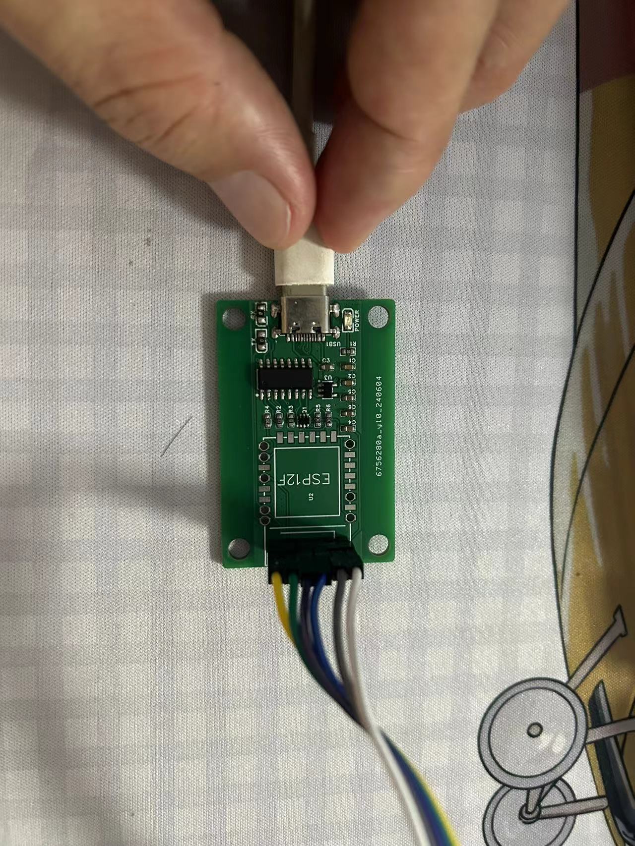
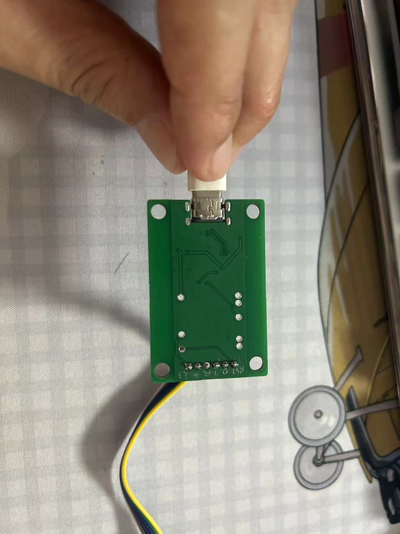
Bring out the BOOT and RST pins and connect them to enable automatic downloading.
Solder on the probes to program modules such as the ESP-F12S.
Since all my boards have six leads, simply clip them on for automatic downloading and restarting, facilitating debugging. This has been verified.
Compared to the SL2.1A USB hub, the CH334R supports a more advanced MTT (Multi-Trip Transfer) mode.
The CH334 and CH335 are 4-port USB hub controller chips compliant with the USB 2.0 protocol specification. Upstream ports support USB 2.0 high-speed and full-speed, while downstream ports support USB 2.0 high-speed 480Mbps, full-speed 12Mbps, and low-speed 1.5Mbps. They support both the low-cost STT (Single TT Time-Sharing) mode and the high-performance MTT mode (4 TTs each corresponding to one port, processing concurrently).
TT is divided into single TT and multiple TTs, namely STT and MTT. STT uses a single TT core to time-sharing transactions sent from the USB host to all downstream ports. MTT refers to multiple TTs operating in parallel, with 4 TT cores each corresponding to and processing transactions on one downstream port in real time. Therefore, MTT can provide fuller bandwidth to the connected devices on each downstream port, better supporting concurrent transmission of large amounts of data across multiple ports.
Compared to the SL2.1A project, there are some modifications:
CH334R no longer has VDD18;
CH334R's VDD33 has a 100nF decoupling capacitor added;
CH334R's RESET# pin is no longer needed.
Actual test read and write speeds are acceptable, basically at the upper limit of USB 2.0.

PDF_USB Hub Based on CH334R.zip
Altium_CH334R-based USB Hub.zip
PADS_CH334R-based USB Hub.zip
BOM_CH334R-based USB Hub.xlsx
93972
OLED clock design based on ESP01S
OLED clock design based on ESP01S
The OLED clock design based on ESP01S consists of three parts: a power charging module, a display module, and the ESP01S minimum system.
fans_clock_esp01s-main.zip
PDF_OLED Clock Design Based on ESP01S.zip
Altium_OLED Clock Design Based on ESP01S.zip
PADS_OLED Clock Design Based on ESP01S.zip
BOM_OLED Clock Design Based on ESP01S.xlsx
93973
ESP32C3 development board
An ESP32C3 development board designed with reference to the LCSC ESP32S3 development board form factor.
This is an ESP32C3 development board designed based on the LCSC ESP32S3 development board layout. It features 8MB of onboard Flash memory and supports onboard JTAG debugging. The antenna design, also based on the LCSC ESP32S3 development board, works flawlessly and functions correctly.
PDF_esp32c3 development board.zip
Altium_esp32c3 development board.zip
PADS_esp32c3 development board.zip
BOM_esp32c3 development board.xlsx
93975
STC8H8K64U Minimum System
This development board adopts a through-hole modular design, facilitating the plug-and-play selection of various modules. If additional modules are needed, DuPont wires can be used for connection. All I/O pins are brought out.
I. Briefly explain the precautions for the welding process in

the 3D preview image.
Below is the welding preview image;
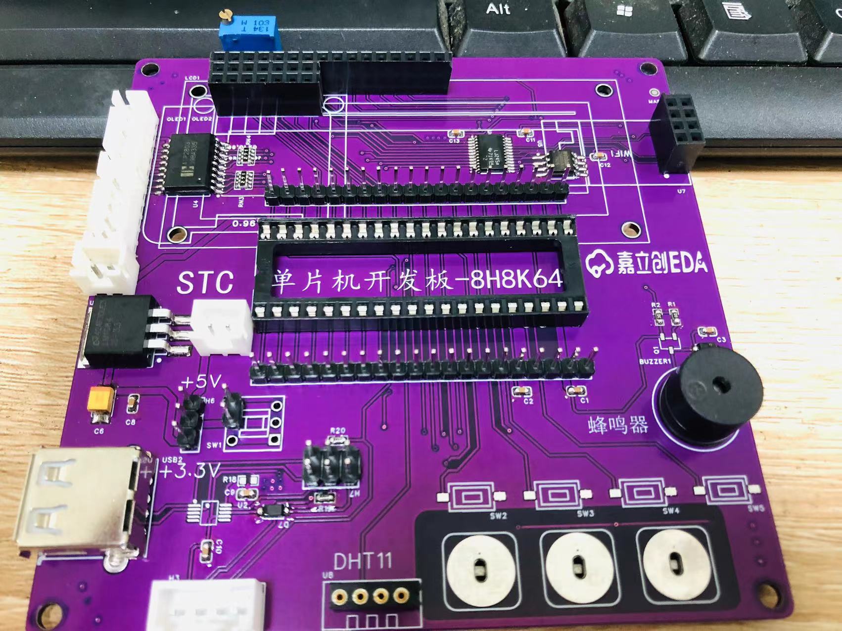

the default is 5V welding. If you choose 3.3V voltage, please note the following:

Position 1 (USB download) does not require welding;
position 2 (sense sensor experiment DS18B20/infrared/DHT11 module, change to round hole pin)
; position 3 (IO→P32, silkscreen SW5);
position 4 (no welding required if not needed); FLASH expansion and 5V to 3.3V logic, all can be welded when VCC is 5V in the above image.

The arrow indicates the FPC LCD display socket, selectively weldable if needed;
the power supply interface also provides a TYPE-C interface, if your soldering skills are not solid, you can choose to weld USB-A, or both.
Also, serial ports P30 and P31 are brought out separately for convenient serial port experiments and for downloading programs to the microcontroller using your own serial port module.
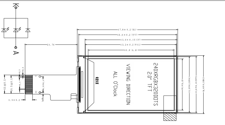
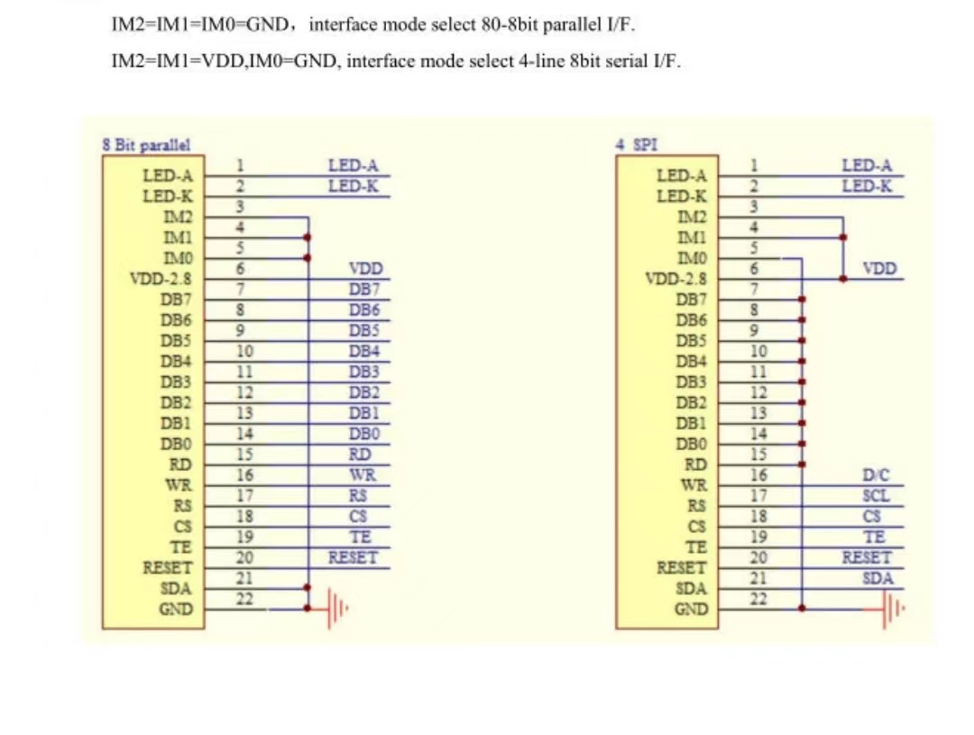
The LCD screen uses a 22P standard interface. As shown in the diagram below
, the second step is to download the program
using the latest STC-ISP software from the official STC company. The default settings are as follows: select 35MHz for the crystal oscillator.

Then, confirm the jumper cap is correct as
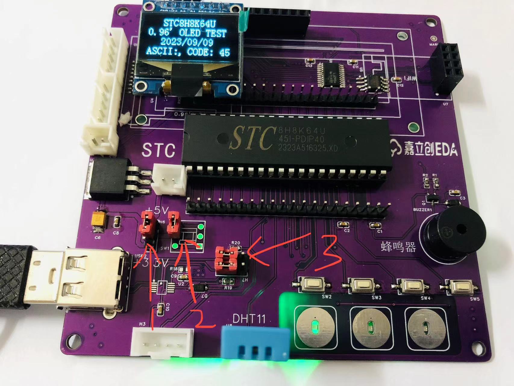
shown in the diagram below: Select 5V for position 1. For position 2, I'm temporarily using a jumper cap; the actual position should be a press-button switch for easy downloading and power-on. Select the left side of the USB port for position 3.
First, press and hold SW5 (P32). After powering on again (marked 2), the following image will appear:

The serial port will display "HID". Release SW5, open the file, and download.
The third step is program testing
. After soldering, you can download the OLED test program I provided. Source code is also provided for
the OLED: 0.96-inch, SPI 7-pin, control chip SSD1306.
The fourth step involves some I/O ports being combined for easier use of hardware I2C and SPI, offering both software and hardware driver options. This is for you to explore.
STC8H8K64U0.96OLED_SPI_Examples.zip
OLED.hex
STC8H8K64U.mp4
stcai-isp-v6.94F.zip
PDF_STC8H8K64U Minimal System.zip
Altium_STC8H8K64U Minimal System.zip
PADS_STC8H8K64U Minimal System.zip
BOM_STC8H8K64U Minimum System.xlsx
93976
MP2236-5V Power Conversion Module
5V step-down module based on MP2236 chip (verified)
This 5V 6A high-current step-down chip is suitable for powering servos and motors. It features
adjustable output (simply modify one resistor value according to the datasheet)
and a wide voltage input range.
MPS-MP2236.pdf
PDF_MP2236-5V Power Conversion Module.zip
Altium_MP2236-5V Power Conversion Module.zip
PADS_MP2236-5V Power Conversion Module.zip
BOM_MP2236-5V Power Conversion Module.xlsx
93979
Fan controller
The GP9101-F20K-L2H1-SW is used as the ADC chip to output PWM control for a four-wire computer fan.
The GP9101-F20K-L2H1-SW is used as the ADC chip to output PWM control for a four-wire computer fan. A diode is added to prevent excessive current from being generated when the fan is turned off. A bracket is designed to work with a variant of the Noctua fan's open-source fan shroud, suitable for office desktop fans. The PWM signal pins have select pads; pin 1 connected to pin P reduces airflow when the potentiometer is rotated in the off direction, while pin 2 connected to pin P does the opposite. Bracket adapter
download address: https://makerworld.com.cn/zh/models/195395#profileId-122615
Fan shroud download address: https://www.printables.com/model/896133-nv-aa1-12-airflow-amplifier-trunnion-mount The fan shroud must be the version with a fixed lug distance of 135!
Fan cover: https://makerworld.com.cn/zh/models/171909#profileId-123350
The ph2.0 socket is not needed.

PDF_Fan Controller.zip
Altium_fan_controller.zip
PADS_FanController.zip
BOM_Fan Controller.xlsx
93980
18650 battery module based on TP5400 capable of simultaneous charging and discharging with 5V output.
Based on the TP5400, this 18650 battery module features simultaneous charging and discharging with 5V output and IP3005A over-discharge protection.
The TP5400-based 18650 battery module features
IP3005A over-discharge protection, shutting off when the voltage is below 3V
and outputting 5V when the battery voltage is above 3V.
It has already been used in the AbenFan Pro project.
PDF_TP5400-based 18650 battery module with simultaneous charging and discharging 5V output.zip
Altium_TP5400-based 18650 battery module with simultaneous charging and discharging 5V output.zip
PADS 18650 Battery Module Based on TP5400 with Simultaneous Charging and Discharging 5V Output.zip
BOM_TP5400-based 18650 battery module with simultaneous charging and discharging 5V output.xlsx
93981
electronic
 This solution, sourced from Taobao seller "Old Wang's," uses a 1-second boost converter, thus exhibiting power consumption and transient power issues. Video:


 京公网安备 11010802033920号

 TDC184050NSE-F


