PCB design tutorial video for Project 1, using the JLCPCB EDA Professional Edition.
[PCB Design Tutorial Video (Project 1, JLCPCB EDA Professional Edition)] https://www.bilibili.com/video/BV1ns4y1
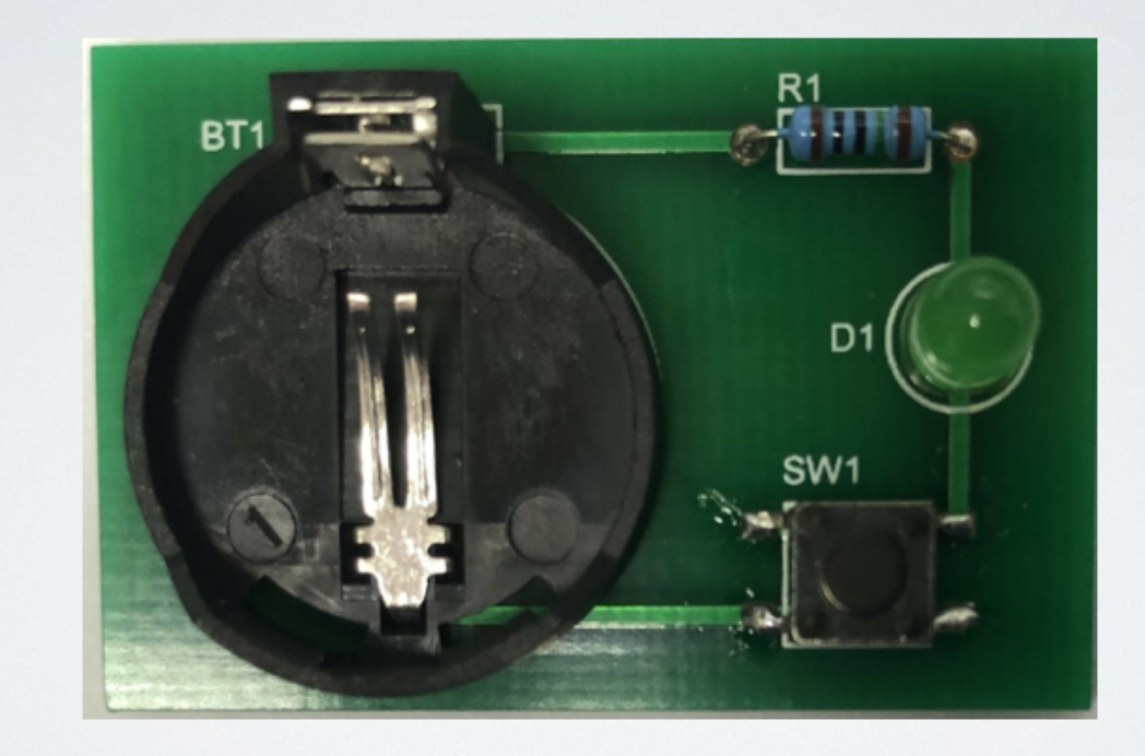
Altium_PCB Design Step-by-Step Tutorial Video Project 1: Button Control of LEDs.zip
PADS_PCB Design Step-by-Step Tutorial Video Project 1: Button Control of LEDs.zip
BOM_PCB Design Step-by-Step Tutorial Video Project 1: Button Control of LEDs.xlsx
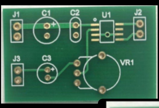
PCB Design Step-by-Step Tutorial Video - Project 2: JLCPCB EDA Professional Version [PCB Design Step-by-Step Tutorial Video (Project 2, JLCPCB EDA Professional Version)] https://www.bilibili.com/video/BV1JT411H7YC
Altium_PCB Design Step-by-Step Tutorial Video Project 2: Power Amplifier Circuit.zip
PADS_PCB Design Step-by-Step Tutorial Video Project 2: Power Amplifier Circuit.zip
BOM_PCB Design Step-by-Step Tutorial Video Project 2: Power Amplifier Circuit.xlsx
PCB Design Step-by-Step Tutorial Video Project 2: JLCPCB EDA Professional Version [PCB Design Step-by-Step Tutorial Video (Project 3, JLCPCB EDA Professional Version)] https://www.bilibili.com/video/BV16z4y1Y7ft
[Supporting Engineering
PCB Design Step-by-Step Tutorial Video: Project 2 - JLCPCB EDA Professional Version
PCB Design Tutorial Video (Project 3, JLCPCB EDA Professional Version)] https://www.bilibili.com/video/BV16z4y1Y7ft
PDF_PCB Design Step-by-Step Tutorial Video Project 3: Hearing Aid Circuit.zip
Altium_PCB Design Step-by-Step Tutorial Video Project 3: Hearing Aid Circuit.zip
PADS_PCB Design Step-by-Step Tutorial Video Project 3: Hearing Aid Circuit.zip
BOM_PCB Design Step-by-Step Tutorial Video Project 3: Hearing Aid Circuit.xlsx
93987
Ultrasonic ranging based on 51 microcontroller
❀
The system description required by the question
: Ultrasonic ranging can be used for car reversing radar, obstacle avoidance of robots and cars, liquid level detection, etc. It is a convenient, fast and reliable non-contact detection method. This design uses an ultrasonic probe to make an automatic ranging device.
System functional requirements: (1) The ultrasonic transmission and reception functions are normal and can display the distance of obstacles in real time (digital tube or LCD display is not limited); (2) This design requires the ultrasonic probe to design the transmission and reception circuit by yourself, and the use of ready-made modules is not allowed. (3) Differentiate alarms when the distance is less than 30cm and 15cm. Less than 30cm is the warning distance and less than 15cm is the danger distance; the measurement distance error is less than 2%; it has a mechanical installation design, is easy to use and has good practicality.
Tips:
1. This design requires a certain foundation in analog electronics and good circuit welding skills. Unreasonable circuit welding, component layout and wiring may directly lead to failure;
2. Differentiate between R and S probes;
3. Check the quality of the probe before welding to ensure that the probe is normal.
Problem Analysis
Hints: Analyze and explain the entire problem or the main part of the problem content.
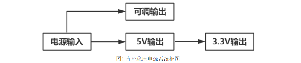
Hints: Overall design scheme block diagram:
Schematic diagram design description

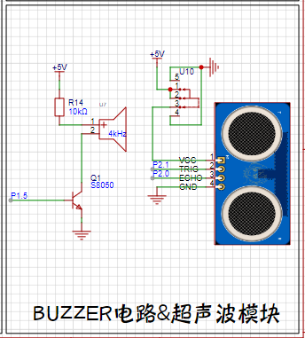
Ultrasonic module schematic diagram (refer to CS100A ultrasonic transceiver module design circuit)
Microcontroller minimum system:
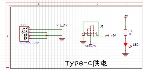
(1) Type-C power supply
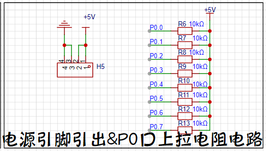
(2) P0 output pull-up
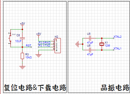

buzzer alarm circuit:
Ancient LCD display:

PCB design instructions
Hints: Here are some design instructions for the PCB, such as: PCB layout, wiring, line width, spacing and other design considerations
Software instructions
Hints: Software can be nested using code blocks. It is not necessary to explain all parts of the software. Only the important parts need to be explained. Code block:
#include
void main()
{
printf(""/n);
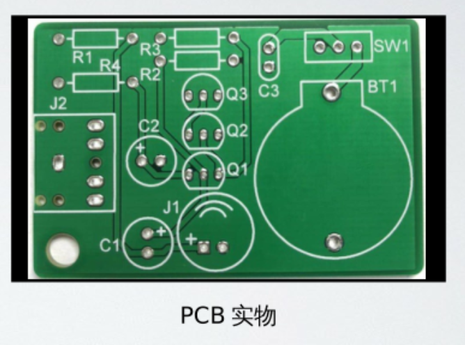
Physical
Demonstration Instructions

and Precautions
: This section outlines some important considerations during the creation of your work (optional).
Demonstration Video
Instructions: Upload your demonstration video as an attachment. Attachments can only be uploading files up to 50MB. Files larger than 50MB can be hosted on other cloud storage services or video websites; simply include the link here.
Other Attachment Upload
Instructions: Entries participating in this event must upload all relevant program attachments to an open-source platform or your personal code storage cloud. Attachments can be uploaded up to a maximum of 50MB (please do not upload to the LCSC workspace, as there are limitations).
PDF_Ultrasonic Ranging Based on 51 Microcontroller.zip
Altium_Ultrasonic Ranging Based on 51 Microcontroller.zip
PADS_Ultrasonic Ranging Based on 51 Microcontroller.zip
BOM_Ultrasonic Ranging Based on 51 Microcontroller.xlsx
93988
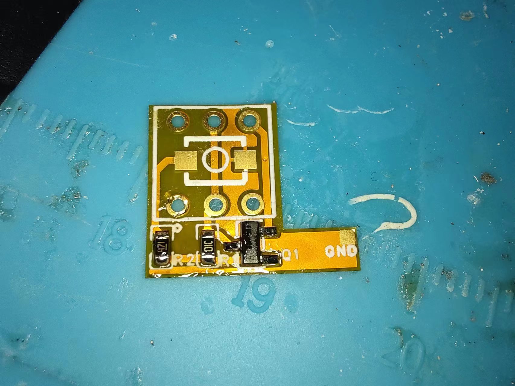
51 Microcontroller - Puzhong A2 - Cold Start Button
A flexible printed circuit (FPC) based on an NMOS transistor for switching on and off
; FR-4 (both can be used).
Commercial use is strictly prohibited without permission!
LGPL 3.0
is prohibited for commercial use and sale by replicators.
I. Function Introduction
This project replaces the original board's self-locking switch with a tactile switch for easier downloading and debugging. The self-locking switch requires two presses to activate the download function (STC-ISP).
Specifically, the power is disconnected when pressed and restored when released (a cold start process). A demonstration video follows
. Disadvantage: This cold start button cannot disconnect the power when not pressed (power off can only be achieved by unplugging the USB).
Advantage: A single touch completes the cold start.
II. Implementation Steps and Precautions
This project can use FPC/FR-4 to replicate the FR-4 board. Try to make the FR-4 board as thin as possible; otherwise, it may have poor soldering.
The PCB file can be directly replicated (ignore errors).
① Remove the self-locking switch from the original board (after removal, you don't need to remove the solder).
Precaution: The surface must be smoothed.
② Solder some components from the FPC or FR-4 small board.
③ Solder the small board to the 51 microcontroller development board and then solder the switch (use this order if possible, as it's easy to burn the switch with the soldering iron if you don't).
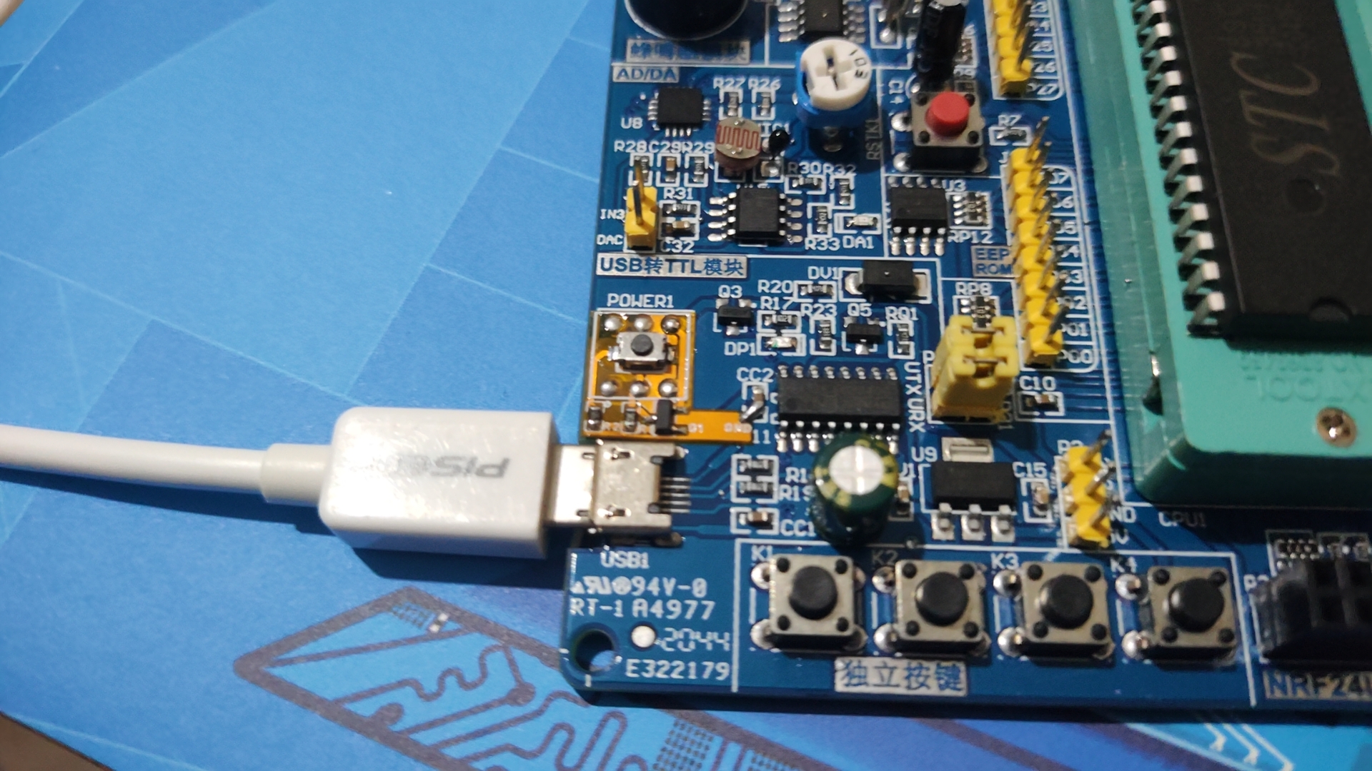
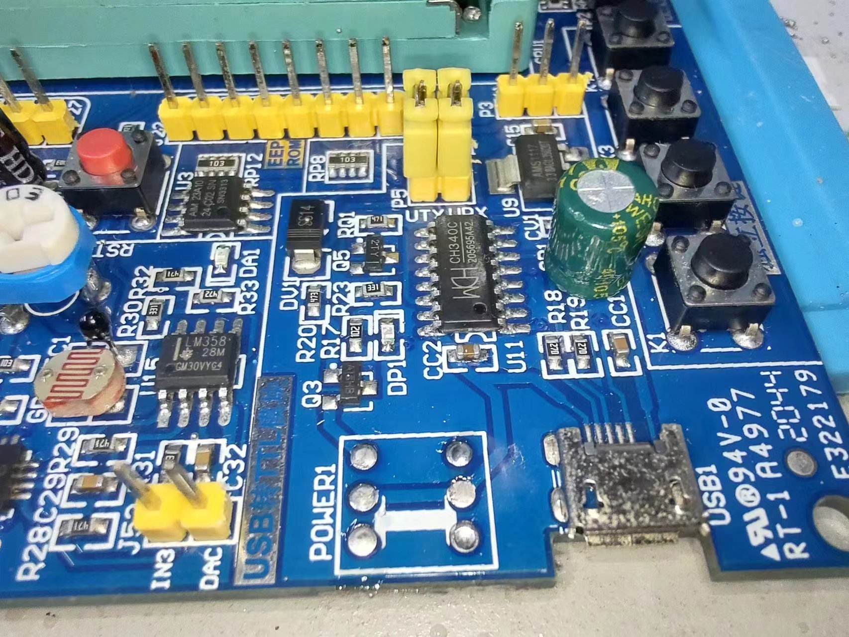
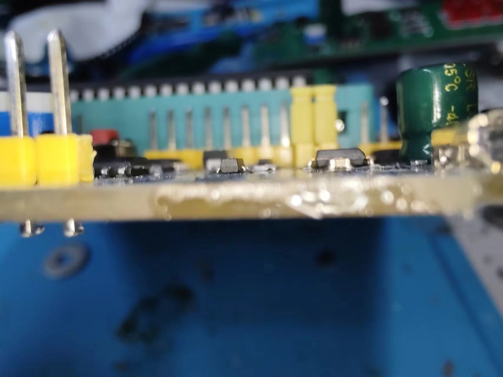
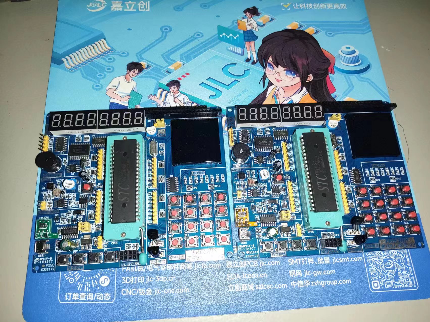
III. Physical Demonstration

IV. Cold Start Video (below)
WeChat_20240701231950.mp4
PDF_51 Microcontroller-Puzhong A2-Cold Start Button.zip
Altium_51 Microcontroller-Puzhong A2-Cold Start Button.zip
PADS_51 Microcontroller-Puzhong A2-Cold Start Button.zip
BOM_51 Microcontroller-Puzhong A2-Cold Start Button.xlsx
93989
A high-brightness flashlight based on the ATmega328P main control chip
A high-brightness flashlight with 8W peak power and 3W continuous power, based on the ATmega328P main controller, IP5407 power management, and LGS63030EP LED driver.
The IP5407
is a multi-functional power management SoC integrating a boost converter, lithium battery charging management, and battery level indicator, providing a complete power solution for power banks. Its high integration and rich functionality require very few external components, effectively reducing the overall solution size and BOM cost. The IP5407 uses only one inductor to achieve both buck and boost functions, supporting low-cost inductors and capacitors. The IP5407's synchronous boost system provides 2.1A/2.4A output current with a conversion efficiency of up to 93%. Under light load, it automatically turns off the LED power indicator and maintains a 5V output voltage to enter sleep mode, with the quiescent current dropping below 150uA. The IP5407 uses switching charging technology, providing 2.0A input current with a charging efficiency of up to 91%. Built-in IC internal temperature and input voltage detection intelligently adjust the charging current. The IP5407 supports 4, 2, and 1 LED power display and illumination functions. The IP5407 is packaged in an ESOP8.
The LGS63030EP
is a boost DC-DC LED driver chip with an integrated power switch and a wide input voltage range of 3V to 60V. It integrates soft-start, minimizing the need for external surge suppression components, making it ideal for driving LEDs with a wide input power range. The output current can be adjusted via an external resistor. The LGS63030EP features an integrated 350mΩ power switch, providing at least 1.5A of peak input current capability, and excellent load and line transient response. It features a SKIP control mode, combining low quiescent current with a high switching frequency for high efficiency over a wide load current range. Additional features include: soft-start, adjustable output overvoltage protection, thermal shutdown, UVLO undervoltage lockout, and cycle-by-cycle peak current limiting protection. The LGS63030EP allows for high-precision digital and analog adjustment of the output current by selecting different values of the sampling resistor RSence.
Regarding this project
: 1. Due to limited technical skills, the program was written using the graphical programming software Linkboy. The "FLASHLIGHT-PRE.lab" file in the attachment needs to be opened with this software.
2. For U5 (ATmega328P), it is recommended to buy an Arduino NANO and remove it from it. It not only comes with a built-in bootloader and is inexpensive, but also allows you to pre-program it, saving the need for C16, C22, C23, R14, and U6.
3. If you do not pre-program it, the LGS63030EP may be accidentally enabled. It is recommended to flash the program in advance, or temporarily short-circuit the 4 pins of the LGS63030EP to ground.
4. For U1, U2, and U3, you need to remove pin 2 of U1, pin 1 of U2, and pin 6 of U3.
5. PCB1 is made of FR-4 substrate, and PCB2 is made of aluminum substrate. The back of PCB2 should face the battery box, and the pins on both sides should be aligned with the corresponding slots on PCB1. Then, use solder to connect the four solder points between the PCBs.
6. If using the program in the attachment, you need to press briefly and then press and hold for about 1 second to turn the device on or off.
FLASHLIGHT-PRE.lab
LGS63030EP_DataSheet.pdf
IP5407_DataSheet.pdf
PDF_A high-brightness flashlight based on the ATmega328P main control chip.zip
Altium - A high-brightness flashlight based on the ATmega328P main controller. (zip)
PADS - A high-brightness flashlight based on the ATmega328P main controller. (zip)
BOM - A high-brightness flashlight based on the ATmega328P main control chip.xlsx
93991
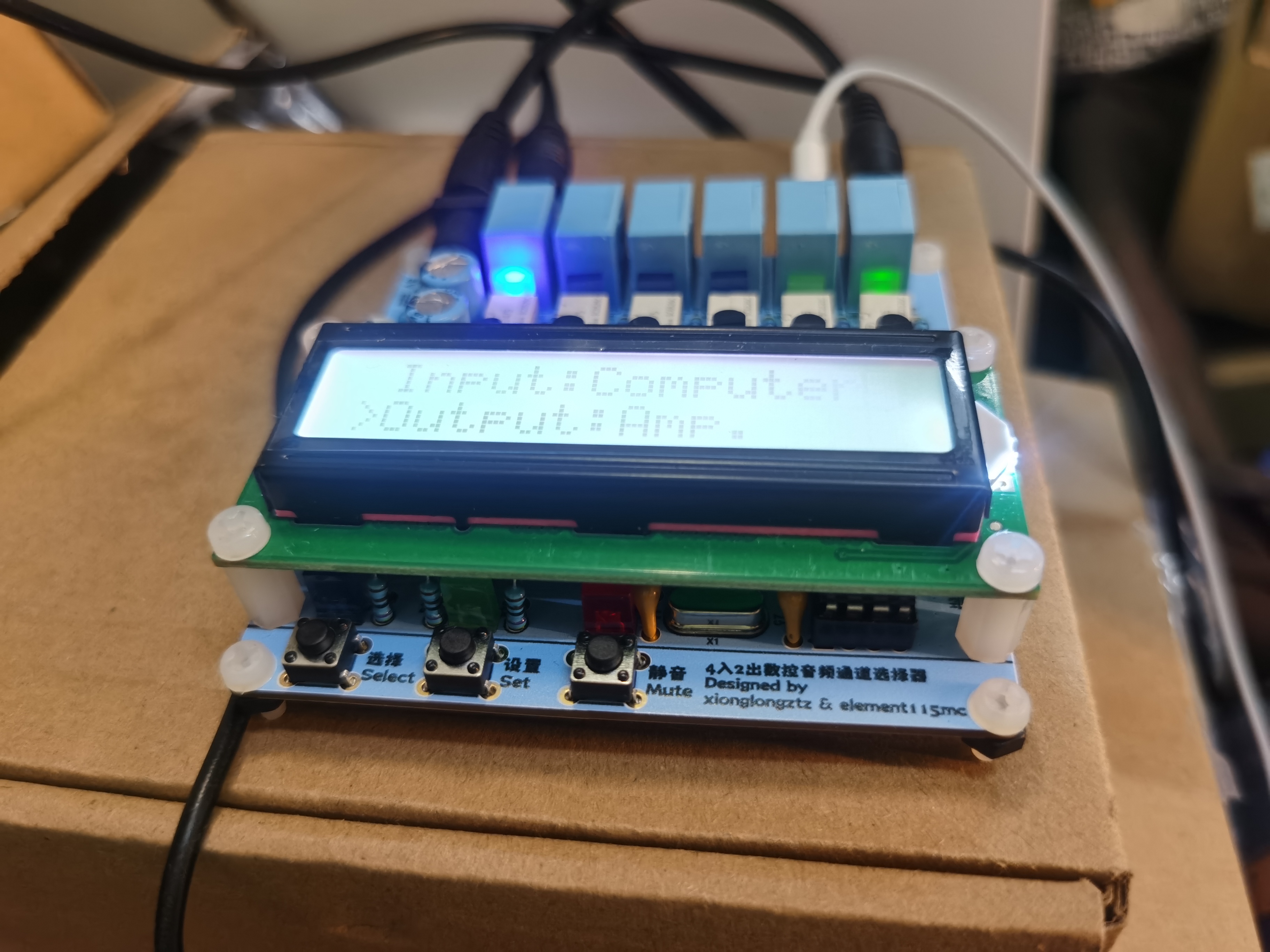
4-in-2-out audio channel switcher
This is a simple audio channel switcher built using the STC89C52, which can easily switch between audio input and output channels.
Have you ever been annoyed by having too many audio devices? When you have multiple computers, game consoles, CD players, or other audio equipment, do you need to connect audio cables one by one?
Or do you have to constantly change plugs every time you replace speakers/headphones, especially in homes with many multimedia devices?
This circuit is an audio channel selector co-designed by me and @element115mc. It supports up to 4 audio inputs and 2 audio outputs, and allows for function selection and switching via buttons.
For aesthetic purposes, the entire PCB silkscreen, audio connectors, and electrolytic capacitors are light blue. The LCD1602 uses a gray backlight
circuit. The main controller is an STC89C52RC, and an AT24C02 is used to store user settings from the previous power outage. Audio input and output are easily controlled via relay switching. The audio
circuitry is isolated from the controller circuitry to prevent signal interference.
The included program contains basic functionalities; users can add additional functions to the controller based on the circuit diagram (e.g., modifying the names of input/output devices on the LCD1602).
The side of the circuit retains serial port programming headers and short-circuit reset headers .
The included program has a self-test function; a clear relay click and the LEDs lighting up sequentially upon power-up indicate normal relay operation. (
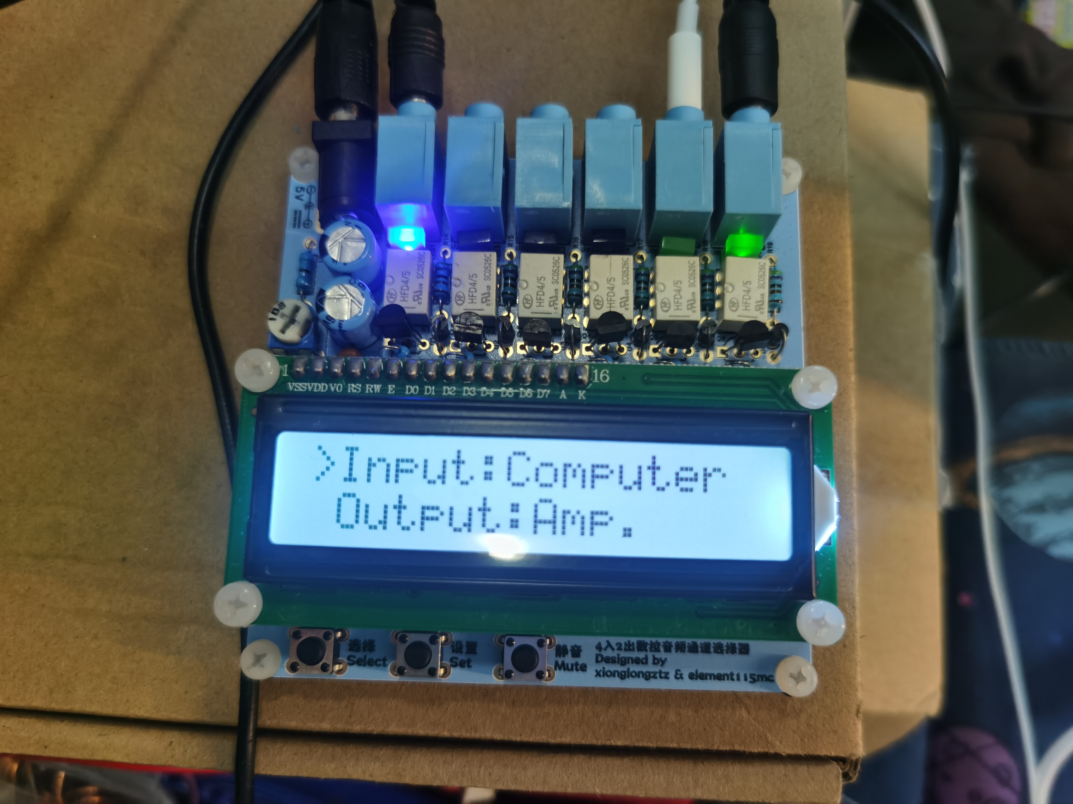
PCB front view,
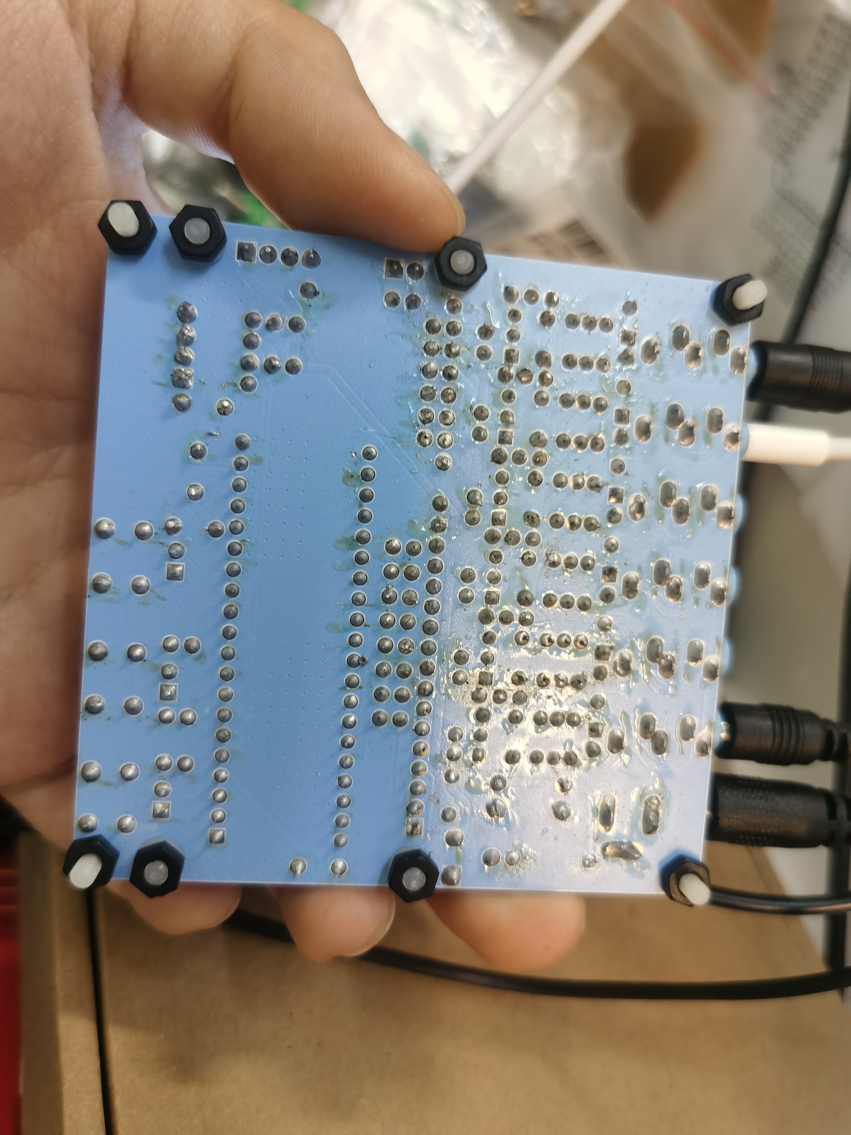
PCB back view , close-up of
buttons, indicator lights, LCD1602, programming
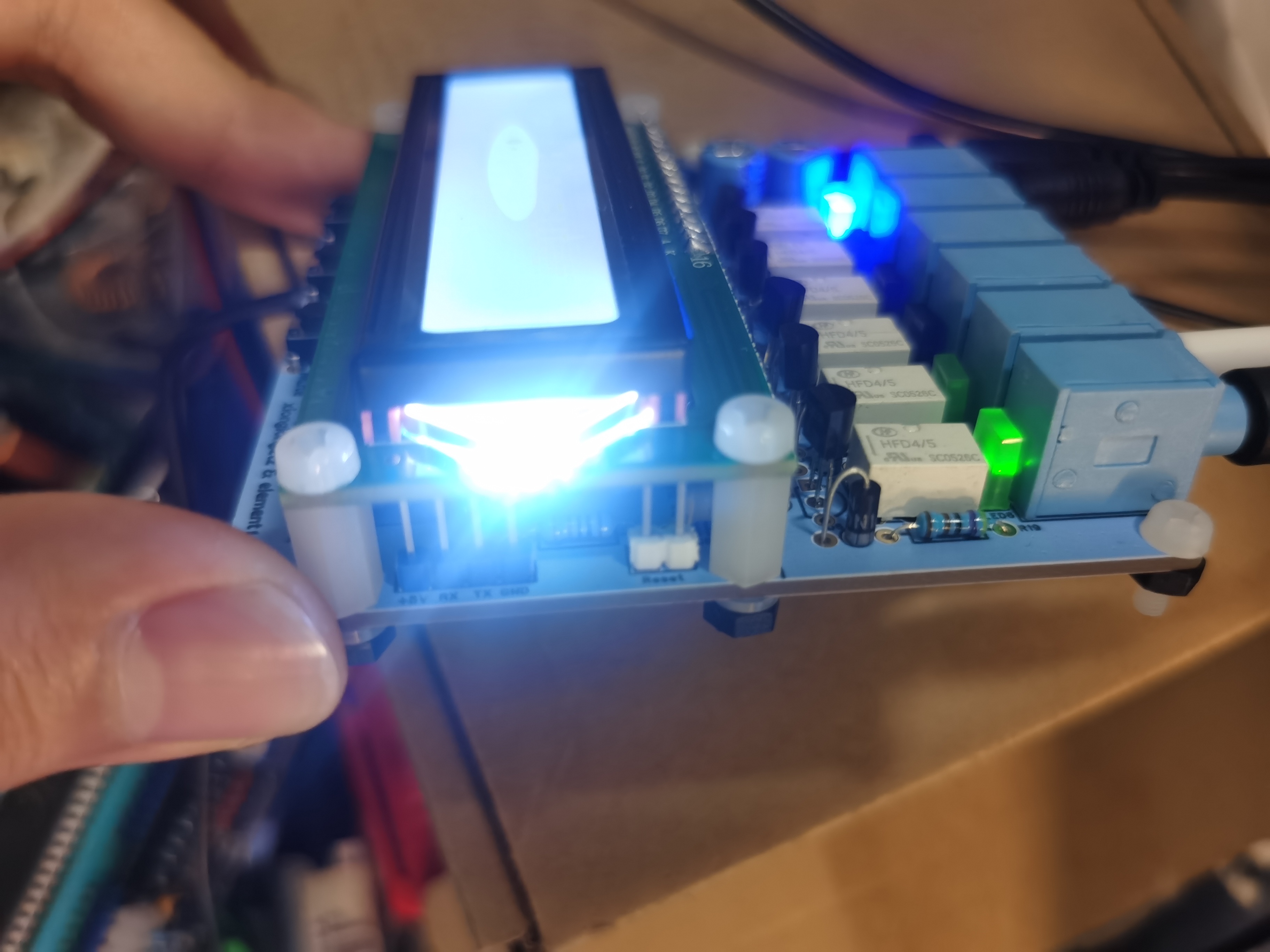
headers, reset headers
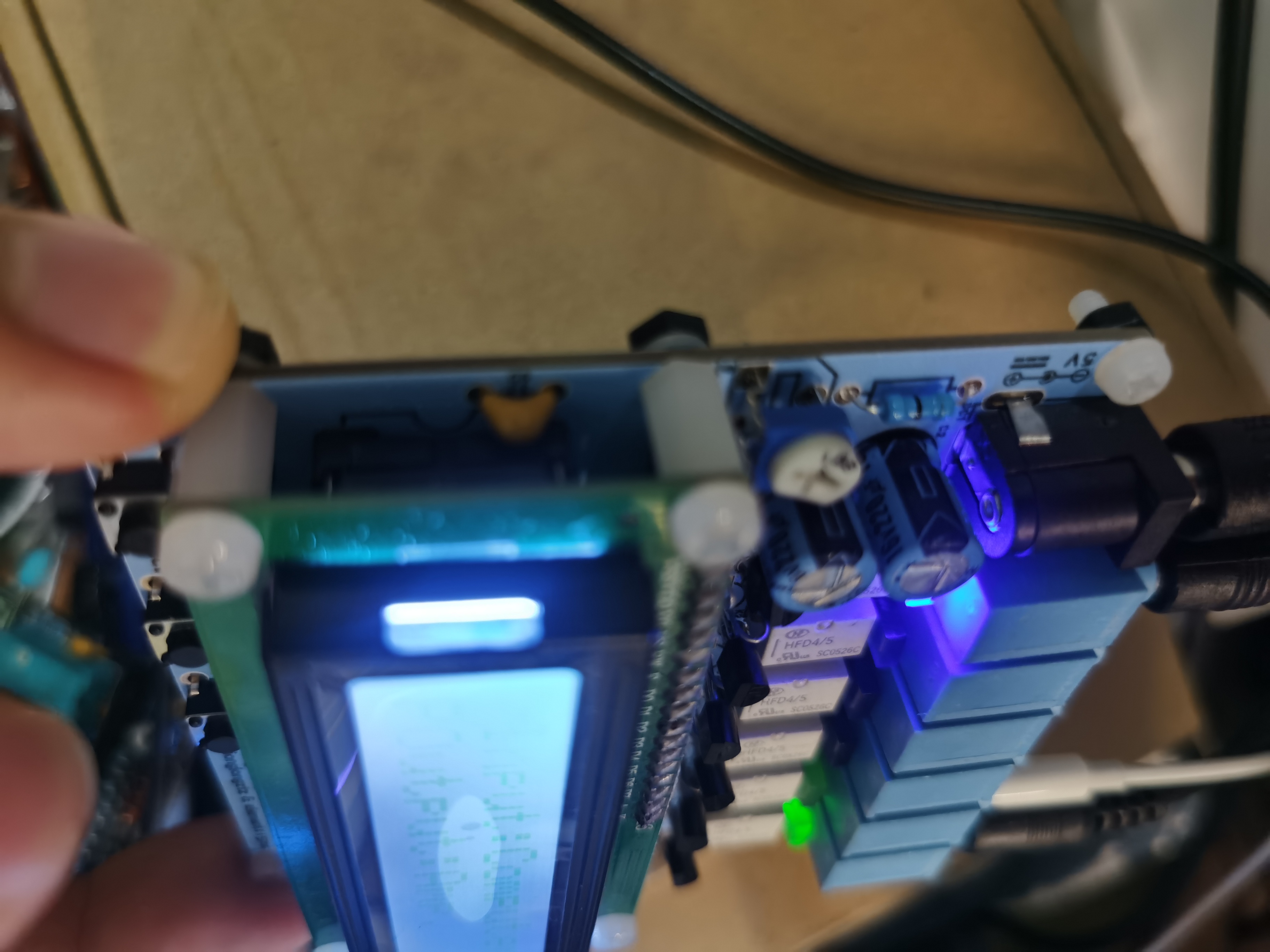
, power interface, electrolytic capacitors, contrast potentiometer close-up)
. Principle: The program controls the corresponding relays via a microcontroller, switching the corresponding audio connection mode to achieve audio channel switching. By reading and writing to the AT24C02 via soft I2C, a power-off data memory function is implemented (recording the user's selections at the time of the last power outage). The current channel is indicated by relay indicator lights, and the LCD1602 displays the information synchronously .
This circuit can be mounted on the casing of speakers or other equipment with screws, or it can be attached to a metal casing surface using internal magnets.
Parameters: Power supply voltage: 5V. No-load current: 0.04A, operating current: 0.13A.
Usage: The "Select" button switches the current selection (displayed as a ">" on the front of the LCD1602), the "Set" button switches the signal of the corresponding channel, and pressing the "Mute" button releases all relays; pressing it again cancels the mute mode.
4in2out.7z
PDF_4-input 2-output audio channel switcher.zip
Altium_4-input 2-output audio channel switcher.zip
PADS_4-input 2-output audio channel switcher.zip
BOM_4-input 2-output audio channel switcher.xlsx
93992
electronic


 京公网安备 11010802033920号

 PI3B16245A


