 schematic diagram, and design description .
  The lithium battery charging circuit uses a TP4056 lithium battery charging chip, with green and red LEDs to indicate whether it is fully charged.
 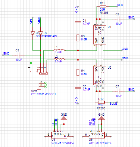 The design concept is based on the fact that only red and blue are used in the game, and these colors are mutually exclusive. Therefore, only two identical voltage regulator circuits are needed, with a switch selecting which regulator circuit to power to achieve color switching.
 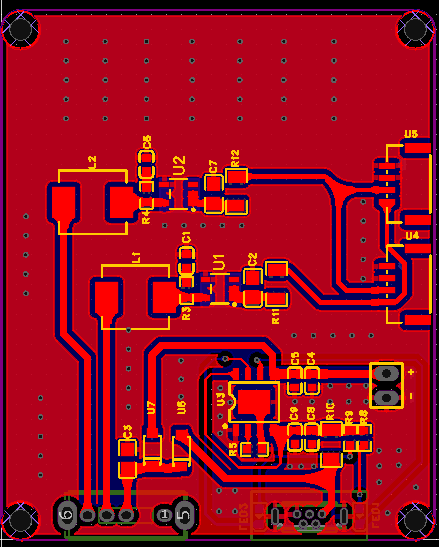 For PCB design, traces requiring current flow are recommended to have a width of 20mil or more. Special attention should be paid to R11 and R12, which are current-limiting resistors for the red and blue LEDs respectively. These need to carry current, so the packages should be changed to 1206. Most resistors will have sufficient power rating. LED brightness can be adjusted by resoldering resistors of different resistance values. In actual testing, using a 20R resistor for current limiting resulted in the LED strip's color difference closest to the official brightness.
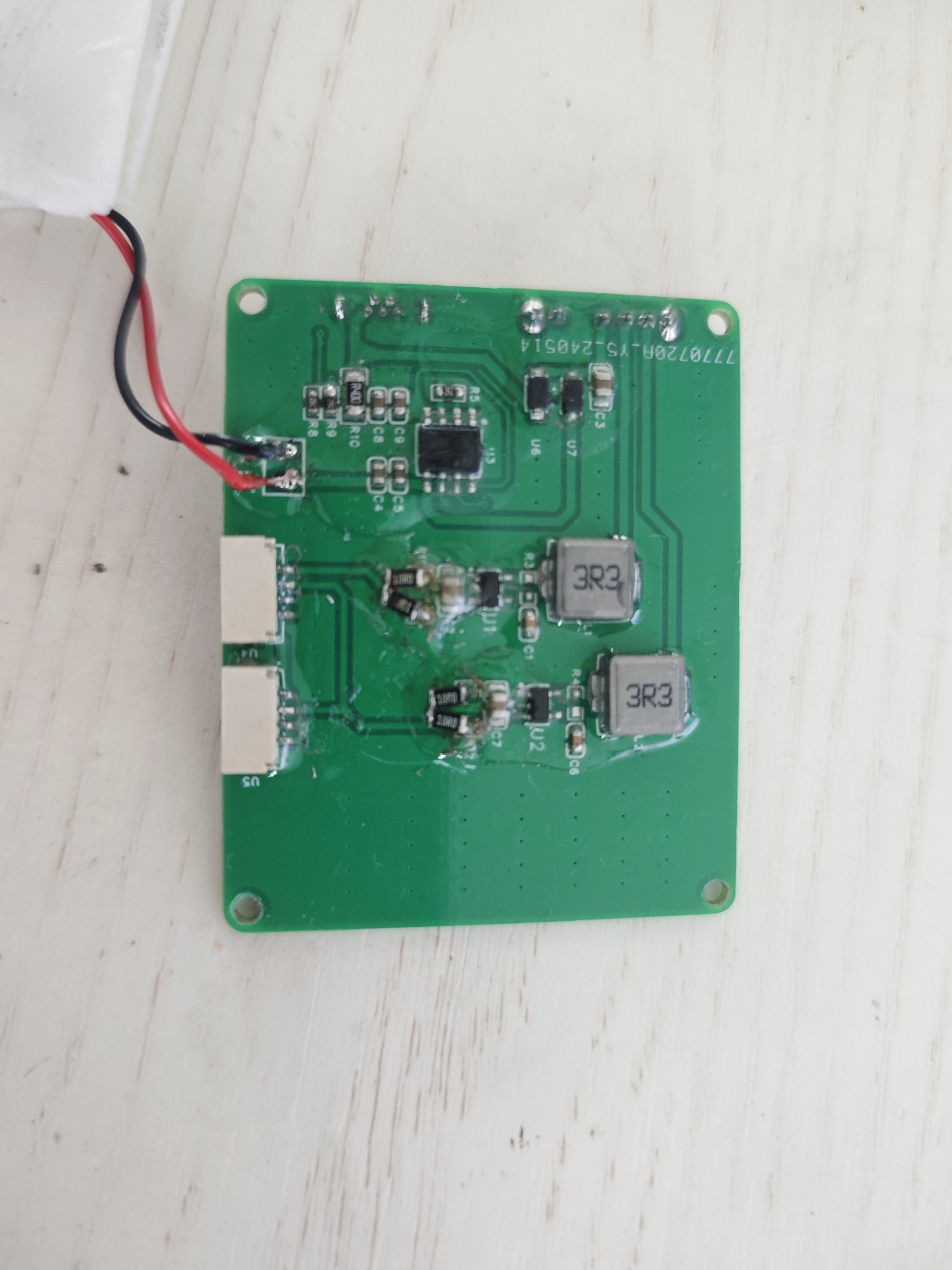 is relatively easy to solder. The smallest resistor and capacitor is only a 0603 package; simply solder them according to the schematic.
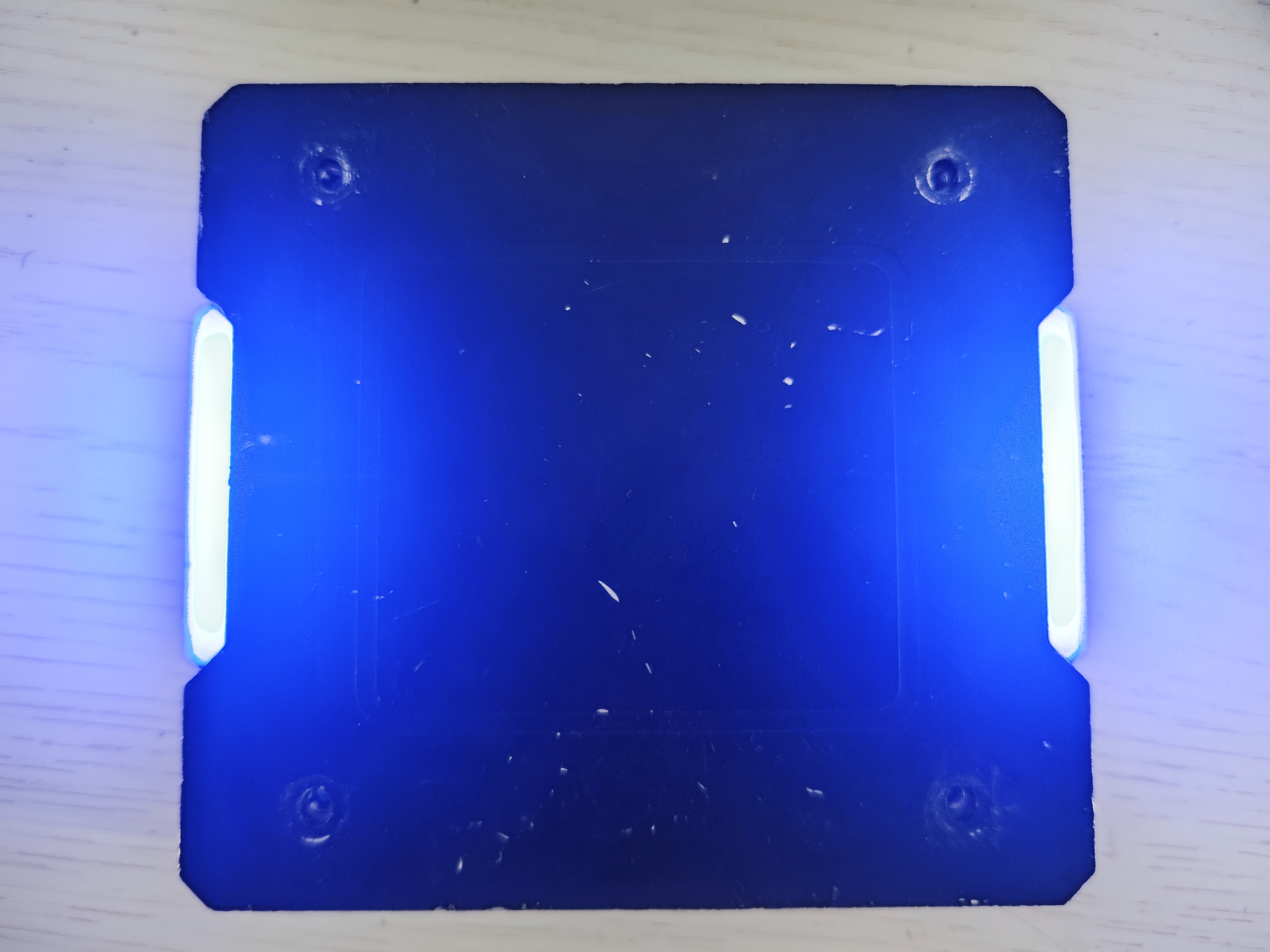
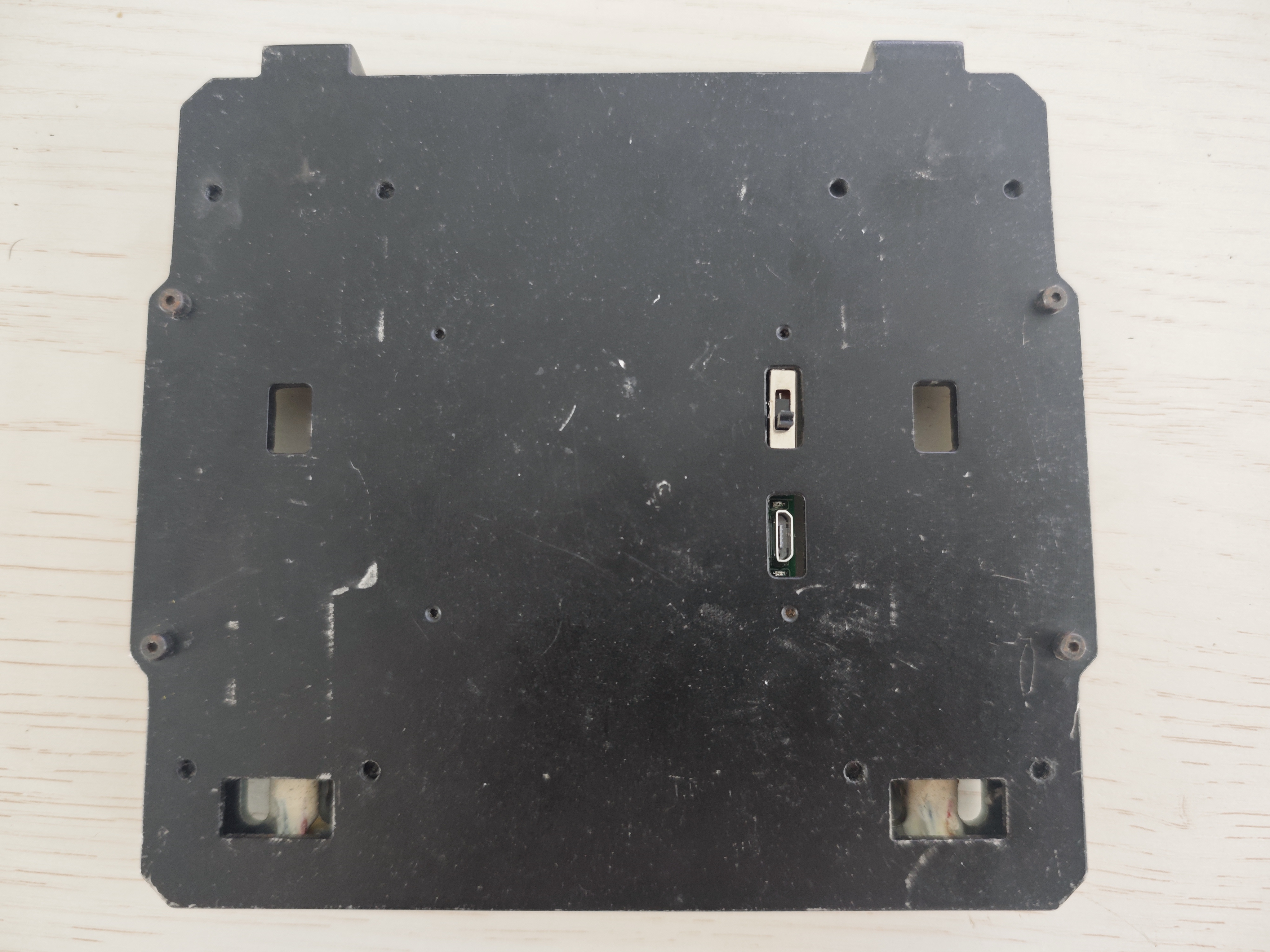 shows the same hole positions as the official original circuit board. In practice, installation simply involves removing the official PCB and replacing it with our custom-made one. Regarding wiring, just connect the two wires of the LED strip to the two GH1.25-4P connectors. Both connectors are identical, and all materials are sourced from the original mounting plate (except for the circuit board).
 :
: 
All reference designs on this site are sourced from major semiconductor manufacturers or collected online for learning and research. The copyright belongs to the semiconductor manufacturer or the original author. If you believe that the reference design of this site infringes upon your relevant rights and interests, please send us a rights notice. As a neutral platform service provider, we will take measures to delete the relevant content in accordance with relevant laws after receiving the relevant notice from the rights holder. Please send relevant notifications to email: bbs_service@eeworld.com.cn.
It is your responsibility to test the circuit yourself and determine its suitability for you. EEWorld will not be liable for direct, indirect, special, incidental, consequential or punitive damages arising from any cause or anything connected to any reference design used.
Supported by EEWorld Datasheet
EEWorld
subscription
account

EEWorld
service
account

Automotive
development
community

Robot
development
community

About Us Customer Service Contact Information Datasheet Sitemap LatestNews


Room 1530, 15th Floor, Building B,
No.18 Zhongguancun Street,
Haidian District,
Beijing, Postal Code: 100190
China
Telephone: 008610 8235 0740
 京公网安备 11010802033920号

 BR93A86RF-W


