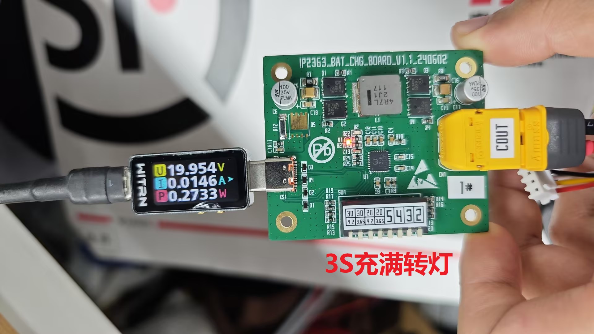
V1.2 Changes: Added a tactile switch. Clicking activates the output. It can output normally when connected to a low-current device (earphone, CC meter). Double-clicking turns off the output.
It has been verified as OK by flying wire. The new PCB board has not been tested.
1. The applicable IC models for this project are: IP2363-BZ and IP2363-Cout;
2. The solution is applicable to: power tools and battery pack charging. It can also temporarily charge mobile phones. It is not suitable for power banks. Remember not to use batteries without protection boards, as this may cause overcharging and over-discharging, which may be dangerous;
3. Currently, only one seller of the Cout version is available on Taobao. If you cannot find it, you can send me a private message. Please refer to the attached BOM for production;
4. Unresolved issues:
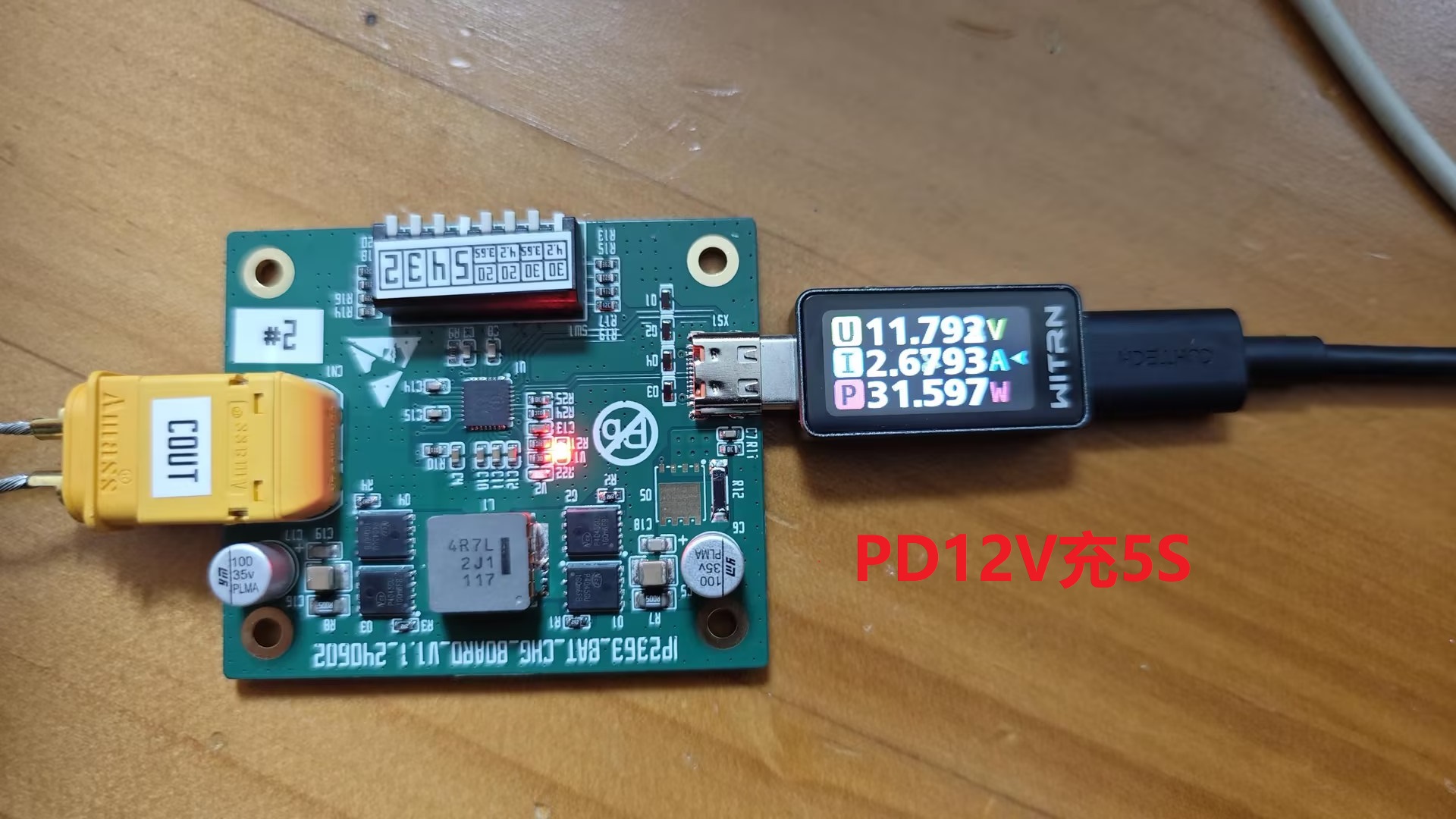
(1) The Cout version cannot be directly tricked into output. It may be necessary to consult the FAE of Ingenic Semiconductor for relevant strategies. No abnormalities have been found when connecting to a mobile phone for charging;
(2) Sometimes the light cannot turn on when fully charged. The solution is the same as above.
5. Please modify the resistance value of the sampling resistor with caution.
I. Design Points
1. MOSFET Selection:
Select according to priority ①-③: ① Ciss < 1000pF; ② Rds(ON) < 10mΩ; ③ Vdss ≥ 30V.
Explanation: Ciss will affect the switching speed of the MOSFET. It is recommended to select one with less than 1000pF. Secondly, consider the on-resistance. The drain-source voltage should be greater than 30V.
Generally, the four transistors are of the same model. If there is a specific application scenario or the cost is very sensitive, you can refer to the explanation provided in the article in "Hard Ten" for selection. It is roughly as follows:
(1) Low duty cycle design: In this case, the PD20V charging head is used to charge 2S and 3S batteries (IP2363 defaults to the highest voltage). The input voltage is high.
The high-side MOSFET is off most of the time. The DC loss is low and the AC loss is high. Select a MOSFET with low gate charge, even if Rds(on) is large. The low-side MOSFET is on most of the time. The AC loss is low and the DC loss is high. Select a MOSFET with low on-resistance, even if the gate charge is high.
(2) High Duty Cycle Design: In such cases, a PD20V charger is typically used to charge 4S or 5S batteries, or a PD12V charger is used to charge 3S batteries. The input voltage is close to the battery voltage.
The high-side MOSFET is on most of the time, resulting in higher DC losses and requiring low on-resistance. Depending on the input voltage, AC losses may not be as significant as with the low-side MOSFET, but they are still not as low, requiring low gate charge. A balance needs to be struck between low gate charge and low on-resistance. The low-side MOSFET has the shortest conduction time and lower AC losses, so the correct MOSFET can be selected based on price or size rather than on-resistance and gate charge.
It is recommended to use the same type of MOSFET for all four MOSFETs, which can save a lot of trouble.
Recommended MOSFET models:
① NCEP4045GU, Wuxi Xinjieneng;
② WSD4076DN56, Weishuo;
③ BSC059N04LS6, Infineon;
④ TMG60N04NF, Taimao; ⑤
CMSA012N06, Guangdong Field Effect Semiconductor;
⑥ SIR8360DP-T1-GE3, Vishay
; ⑦ NTTFS5C466NL-HXY, Huaxuanyang.
①-③ verified, ④-⑦ unverified, ⑦ model is a 3x3 package (if there is a need for further size reduction).
2. Inductor selection:
4.7uH, 8A (the smaller of temperature rise current and saturation current) or higher, DCR < 10mΩ;
3. MLCC Selection:
On the high-voltage path, X5R and X6R/S capacitors should be dated by ≤60%, i.e., withstand voltage ≥35V. X7R and X7S capacitors should be dated by ≤85% (ambient temperature <85℃), i.e., withstand voltage ≥25V.
4. Sampling Resistor:
Select one with 1% accuracy and low temperature drift. Modifying the sampling resistor value will affect the peak power and may burn out the circuit. Do not modify it unless you are certain.
5. Other
Indicator Lights: A dual-light design is recommended because the COUT version requires dual lights to indicate the status. It is best to reserve space in the circuit.
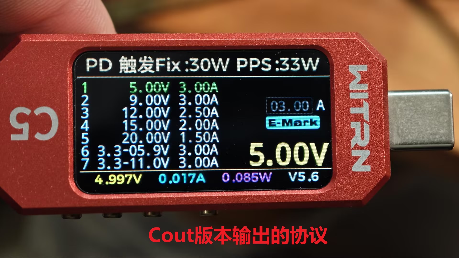
The input and output ranges of the COUT version are bound, meaning that if you set the maximum input to 20W, the output will also be 20W.
The NTC function does not have a reserved interface; it only has a 10K pull-down resistor, which can be brought out externally if needed.
II. Layout and routing
should refer to the requirements in the IP6557 manual attached. Additionally, the following requirements apply:
1. ICs and MOSFETs should have ventilation windows on the BOT side for heat dissipation. The IC hot air pads should have vias. 2. Trace traces
should be routed to both sides of the VBUS pads on the USB-C port.
3. The copper trace at the bottom of the shielded inductor can be retained, but the copper trace at the bottom of the unshielded inductor must be removed. Also, ensure that traces do not run under the inductor.
4. All AGND networks should be connected together for single-point grounding. It is recommended to use a 0R resistor, as this makes it easier to handle on the PCB.
5. Routing priority: USB-C port → sampling line → other lines.
III. Test Data
1. IP2363_Cout Output Efficiency: Efficiency at various current levels and under extreme current at 20V and 11V.
2. Charging Efficiency: Charging efficiency of 3S and 5S batteries at PD20V and PD12V.

3. Temperature Performance: Output and input at room temperature of 26℃ (corresponding to the table above).
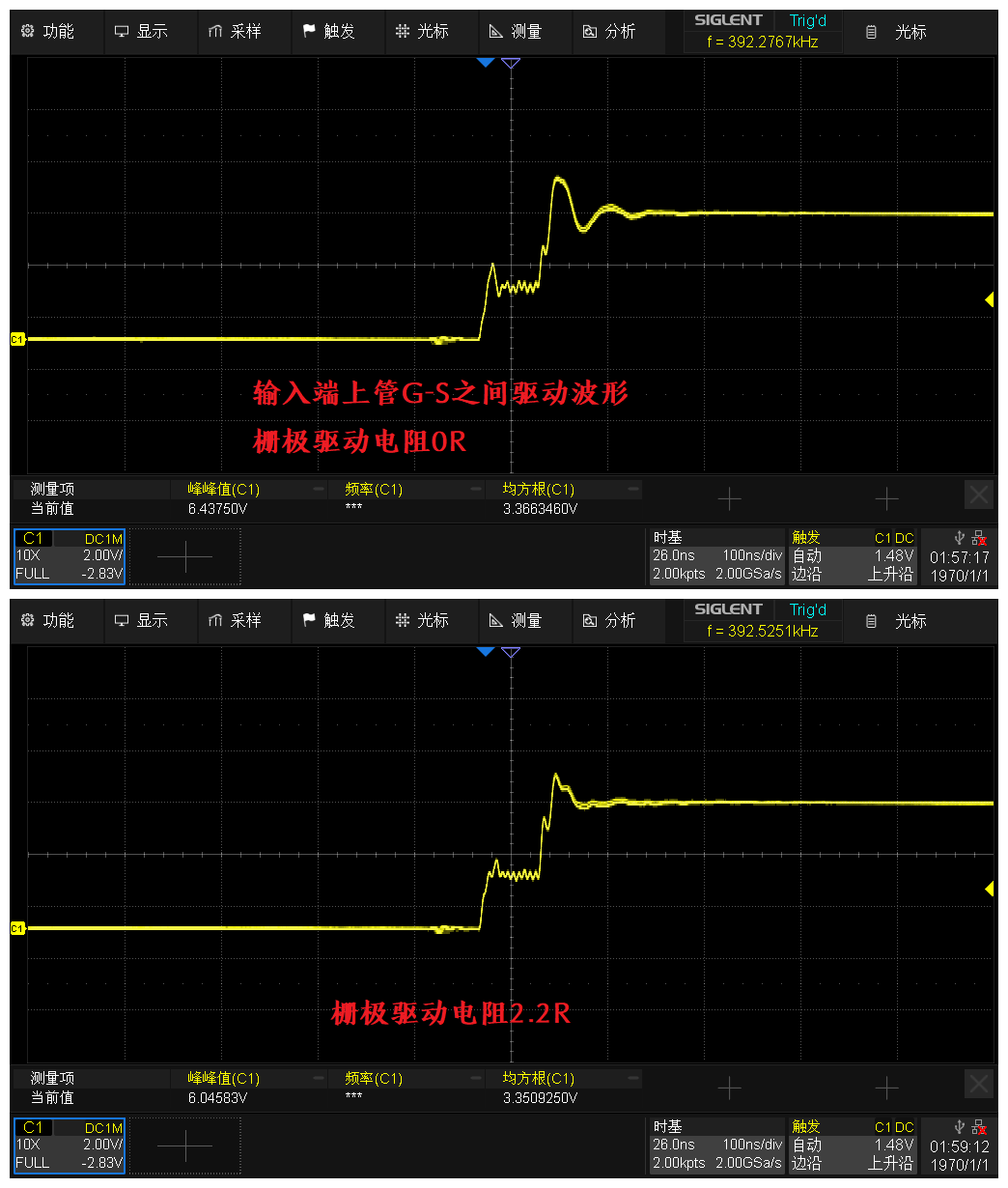
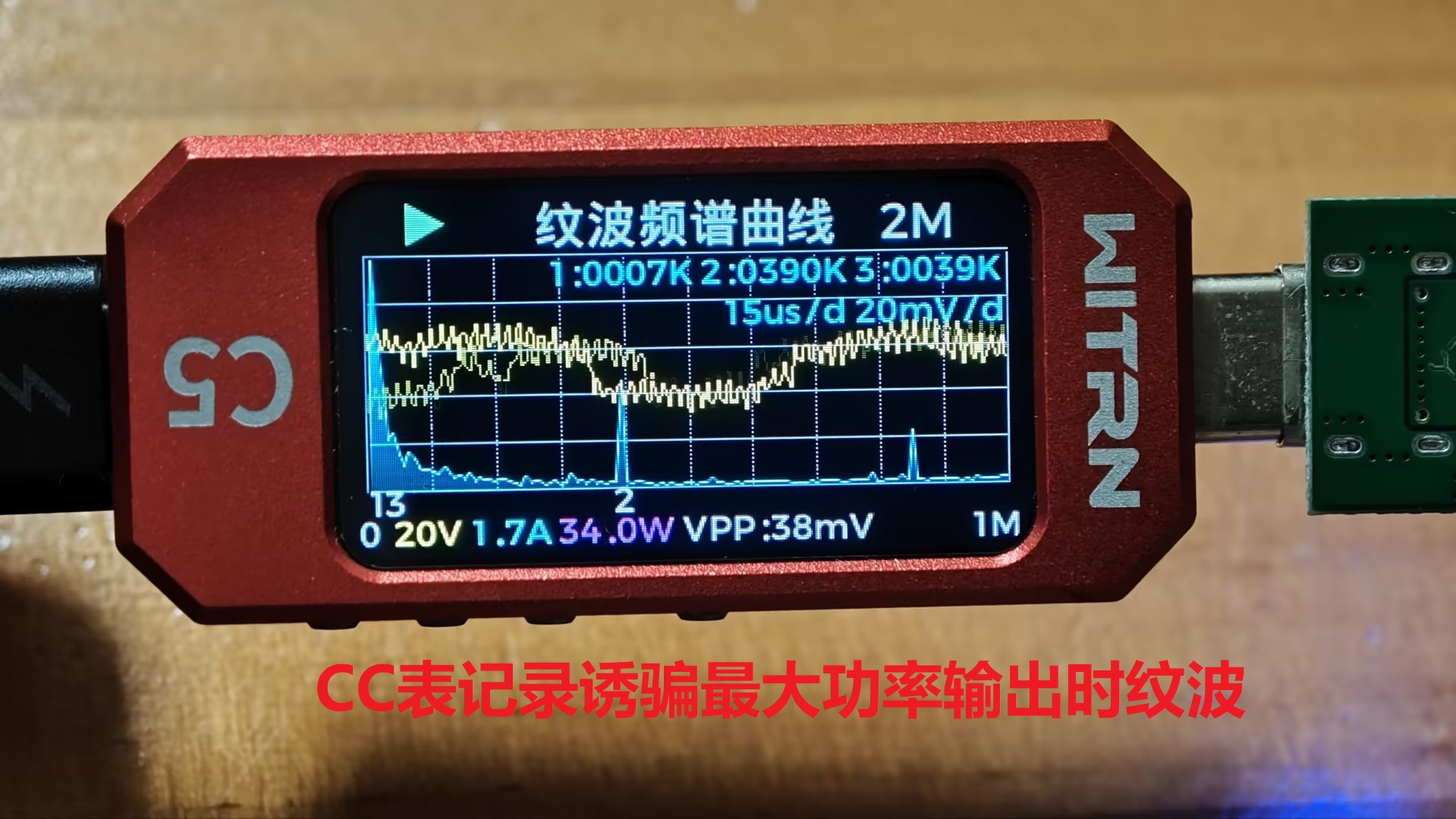
4. Ripple and Drive Waveform
IV. Summary + Others
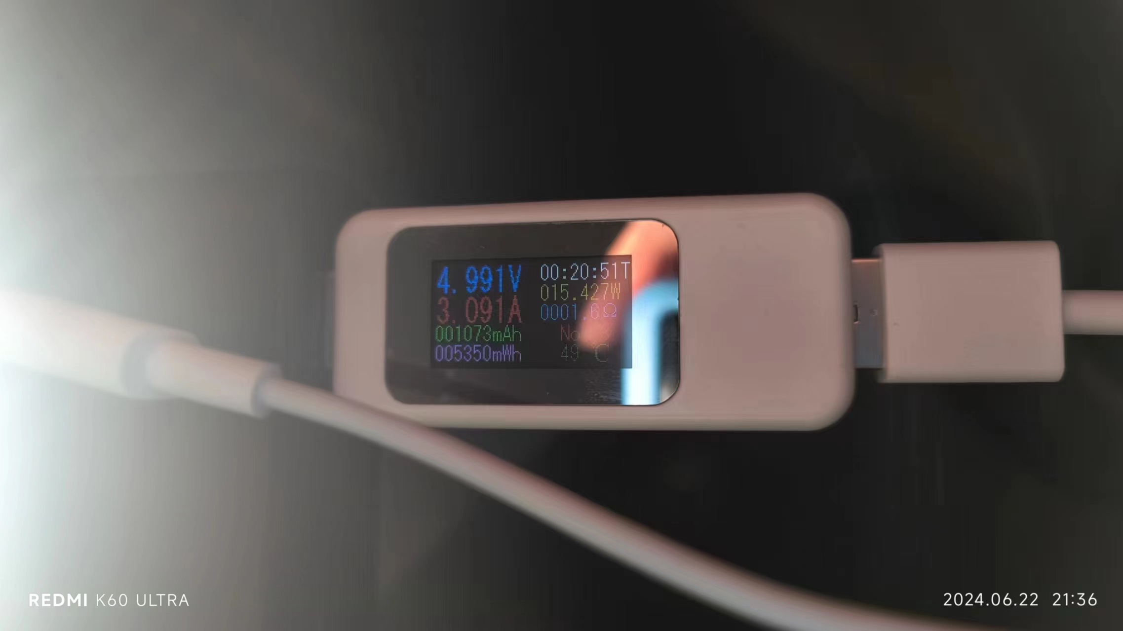
1. Output efficiency, averaging over 90%. It should be noted that when Cout has no output, the decoy device cannot induce a voltage. A voltage and current meter needs to be connected to a mobile phone to activate Cout's output before the protocol can be induced. This strategy is suspected to be related to the IC's firmware.
2. Charging efficiency is above 93% on average.
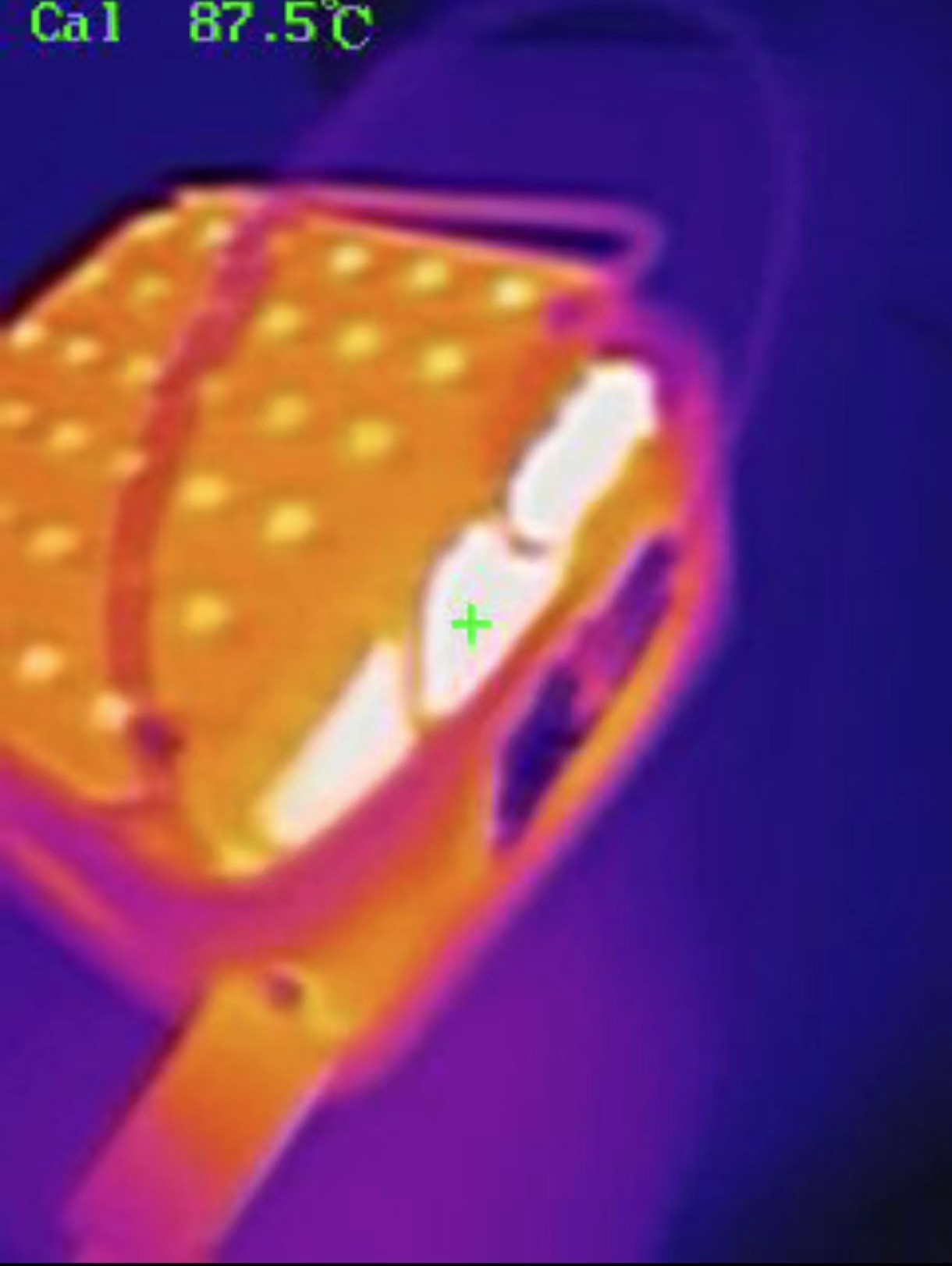
3. Temperature performance: without passive or active cooling, the highest temperature at the 35W output limit is 72℃, and the highest input temperature is 66.5℃.
It should be noted that the chip's internal digital and analog power supplies are converted from the input voltage. The larger the LDO voltage difference, the greater the IC heat generation.
The temperature graph shows that PD20V charging is hotter than PD12V charging. Cooling measures (active or passive) should be strengthened to ensure the IC and MOS operate at lower temperatures to improve stability.
4. Ripple is good. A clear Miller plateau is visible in the gate drive waveform, and ringing is very small at 0R. When using different MOS, the resistor in series with the gate drive needs to be adjusted according to the waveform. If possible, a fast recovery diode (e.g., 1N4148) can be connected in parallel across this resistor to accelerate the MOS turn-off time.
5. Since the external power supply pin of the IC is input from VIO, is it possible to pass through an LDO first and then enter VIO to share the power consumption of the IC? This idea has not been verified.
6. Occasionally, when fully charged, the light will not turn on. The phenomenon is that the light turns on and stays on for 2 seconds and then continues to flash. It can be distinguished by careful visual inspection. This may be related to the firmware. The recharging threshold may have been changed.
7. The NTC function has been verified.

BOM_IP2363 Verification Board.xlsx
Gerber_IP2363 verification board.zip
IP6557.pdf
IP2363.pdf
PDF_IP2363 Verification Board.zip
Altium_IP2363 verification board.zip
PADS_IP2363 verification board.zip
94103
Multi-type Motor Drive Algorithm Learning Board V1.0
A motor drive algorithm learning board designed to meet learning needs, supporting the learning and development of various motor drive algorithms. Code development is underway...
This is a motor drive algorithm learning board designed to meet learning needs. It supports open-loop DC brushed motors, closed-loop DC brushed motor speed (Hall encoder), open-loop DC brushless motors (back EMF, SVPWM), closed-loop DC brushless motor speed (Hall encoder), closed-loop DC brushless motor position (IIC magnetic encoder), open-loop stepper motors, and closed-loop stepper motors (IIC magnetic encoder). It features
12-24V voltage input, reverse polarity protection, an STM32G431C8T6 main controller, four reserved input capture interfaces (TIM3), and reserved communication interfaces: SPI and IIC.
5aad604aa95a970b1eddb456180ba5eb.mp4
484f594095da9f05e05a4aa670075065.mp4
1452f9453c8ac42e6dc1cedc1ed54f71.mp4
PDF_Multiple Types of Motor Drive Algorithm Learning Board V1.0.zip
Altium_Multi-type Motor Drive Algorithm Learning Board V1.0.zip
PADS_Multi-type Motor Drive Algorithm Learning Board V1.0.zip
BOM_Multi-type Motor Drive Algorithm Learning Board V1.0.xlsx
94106
Super Bright "Little Sun"
Ultra-bright full-spectrum lamp, 15W power
The
boards have been verified, but the casing hasn't been assembled yet. An update will be provided after assembly.
There are two boards: one is a plug-in 15W color temperature LED, and the other is a battery-powered LED with a fan function. The LED board can be magnetically attached to the fan, with a power limit of 5W
. Features of the plug-in 15W magnetic LED: Maximum power 15W, the cooling fan turns on automatically when the light is on, ultra-low standby power consumption .
1. Low-cost solution, simple peripherals, no programming required
. 2. Large component packages, easy to solder
. 3. The LED board uses an aluminum substrate, high heat dissipation efficiency, large copper area, and simple common ground driving method
. 4. The casing has magnetic/power supply functions, side-mounted and top-mounted, convenient for dormitory use.
5. Equipped with a cooling fan, no problem with long-term high-power lighting; test videos will follow
. 6. Low standby current, only 130ua/5v
. Features of the battery-powered fan LED:
1. Low-cost fan/power supply IC, using IP6351, only 0.76r, adjustable battery type voltage and charging current.
2. Uses touch buttons to control the fan switch, with 4 speed settings (5V, 7V, 9V) and 3 wind speeds. Also includes a 4-speed natural wind function.
3. Can be used with an external magnetic light, using the same light board as the plug-in model, with a housing and magnetic power supply magnet that can be attached to the front of the fan. The round power supply magnet supports 360° rotation.
4. Low standby current, only 130ua/5V.
II. Schematic diagram explanation:
Uses PT2023S8 touch dimming IC, low power consumption, standby current only 6ua
, multifunctional, simple peripheral circuit.

LED driver
uses LGS63042EP, input 3-60V, output 3-60V, very cost-effective, only 1.3r, still works normally at 87 degrees Celsius, wide operating temperature range -40℃ to... The 125℃

cooling fan circuit
is controlled by the touch-sensitive LO pin output.
III. Physical/Test Images
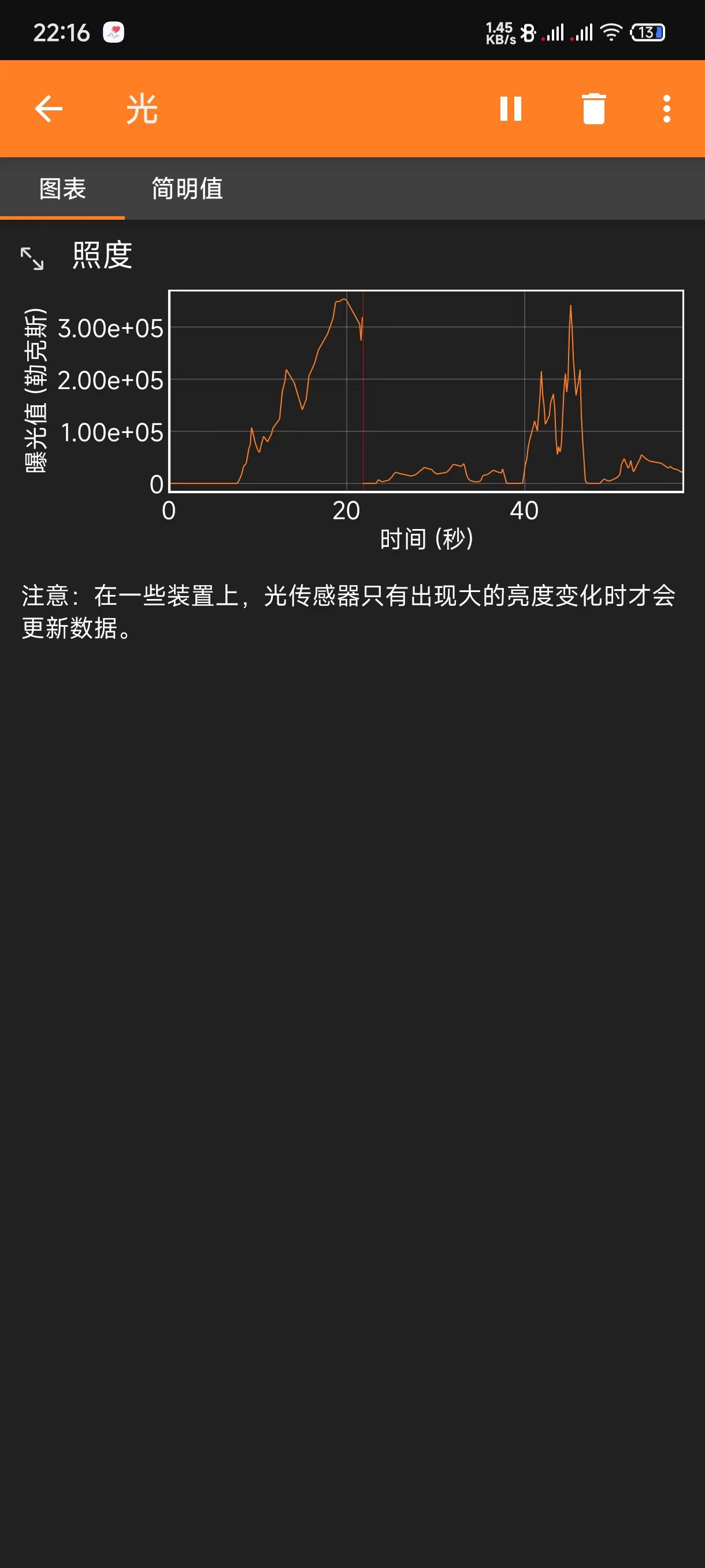
: Brightness photos taken using parameters set in professional mode on a mobile phone camera.
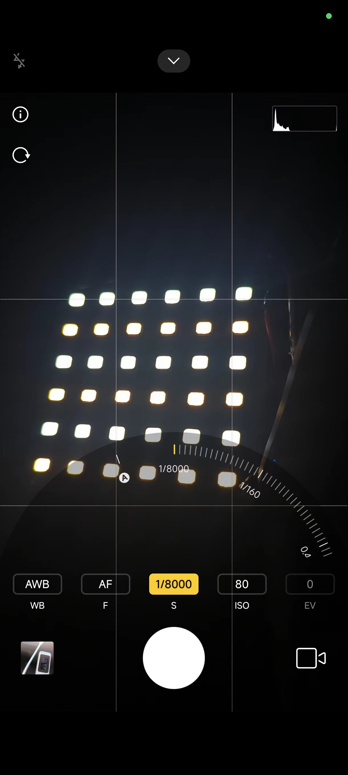
Running at full power for 20 minutes without abnormalities, consuming approximately 5.3Wh. It functions well as a plant light. It uses full-spectrum LEDs. With 8 hours of illumination per day, the monthly electricity cost is approximately 4 RMB. The lamp
board temperature is normal (20 minutes of operation, room temperature 29°C). The inductor temperature is the highest, but overall it functions normally.
The LEDs used are full-spectrum LEDs; violet light excites the phosphor to emit light. White light is used during operation to be invigorating, while warm light is used at night to induce drowsiness. Reference source: Zhihu. Brightness values measured by mobile phone software ( standby power consumption measured by a CC meter


near the LED with the front camera of the mobile phone).

PDF_Super Bright "Little Sun".zip
Altium_Super Bright "Little Sun".zip
PADS_Super Bright "Little Sun".zip
BOM_Super Bright "Little Sun".xlsx
94107
Dragon Slayer Saber Third Generation Reissue
This is a replica of the STC official development board, the third generation "Dragon Slayer," with optional chips: STC32G12K128-LQFP64 or STC8H8K64U-45MHz-LQFP64.
This project is a replica of the STC official Dragon Slayer 3rd Generation development board. The chip options are STC32G12K128-LQFP64 or STC8H8K64U-45MHz-LQFP64.
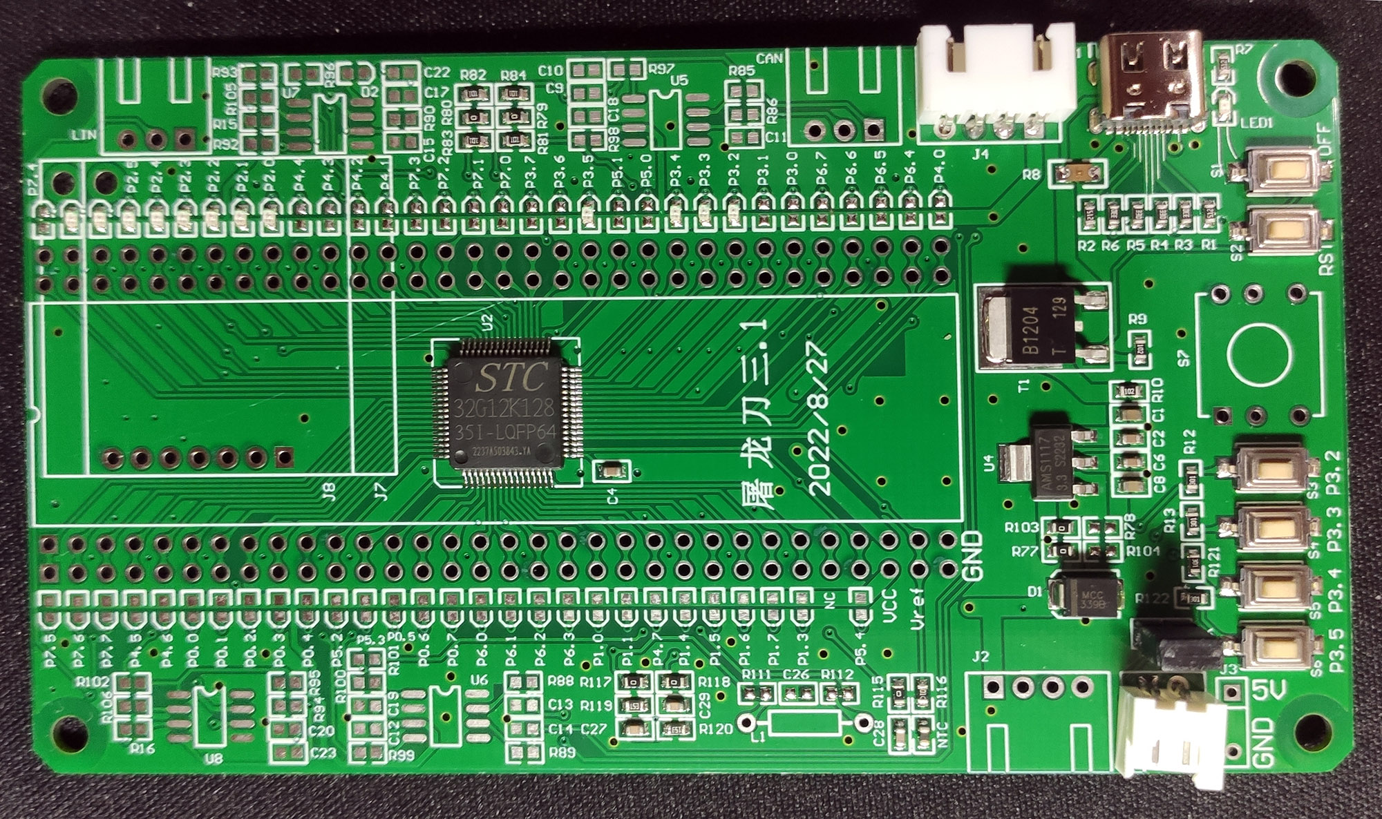
I. Images of the Dragon Slayer 3rd Generation board
; II. 3D demonstration of the development board;
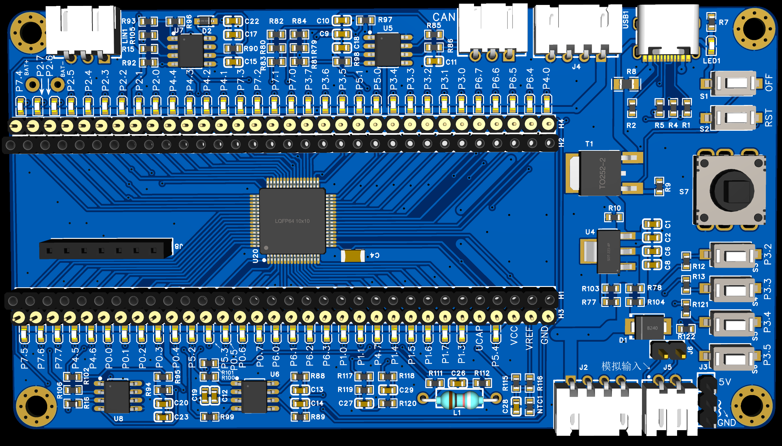
III. Onboard functions:
All chip pins are brought out (H3 and H4 are soldered to header pins).
The onboard LQFP64 chip is converted to DIP64 for outgoing pins (H1 and H2 are soldered to header pins).
All I/O ports have LED indicators (common anode, with current-limiting resistors).
When the LQFP64 chip is not soldered and H1 and H2 are soldered to header pins, a DIP64 interface can be used. The core board
has an anti-static USB Type-C interface that supports downloading and a download button (OFF and S3 buttons) that allows data cable unplugging.
It supports STC USB-Link1 (J4) and STC USB-Link1D (J2+J4). The emulation tool
chip can be selected as 5V or 3.3V, and a 3.3V emulation tool is also available onboard. LDO voltage regulator chip
with 5V power output; when using 3.3V, the 5V power
supply can be used simultaneously. Onboard reset button.
Onboard four programmable buttons (requires internal pull-up, low level when pressed).
Onboard one five-way multi-function switch (joystick - no linear function) (requires internal pull-up, low level when pressed).
Supports AC or DC signal input to the ADC via a 2.54mm pitch XH 2-pin interface (J5, short J6 to test DC, not shorted to test AC).
2.54mm pitch XH 3-pin external CAN bus interface .
2.54mm pitch XH 3-pin external LIN bus interface.
Onboard TJA1050 CAN bus chip (can test CAN transceiver function on the same board when both are soldered).
Onboard independent LIN bus chip supporting external power supply (can test LIN transceiver function simultaneously when both are soldered).
Onboard three PWM DAC conversion circuits, two with second-order RC filters and one with an LC filter. Onboard
circuit board for testing UART transceiver function.
Onboard 7-pin 2.54mm pitch SPI protocol display interface, also compatible with 4-pin... The I2C protocol display
board features an onboard 431 external voltage reference circuit
and an NTC temperature measurement circuit.
IV. The development board can be used for the following experiments:
Marquee experiment,
external interrupt INT0/INT1 experiment,
timer experiment,
serial port experiment ,
ADC experiment
, comparator experiment,
industrial CAN bus transceiver experiment,
automotive LIN protocol transceiver experiment,
PWM experiment,
and FreeRTOS for STC32G12K128 experiment
. V. Development board related materials:
STC32G12K128 datasheet
, STC8H8K64U datasheet,
Dragon Slayer official example code package
download, simulation user manual, Dragon Slayer - Burning - Uninterrupted Download - Simulation User Manual,
Dragon Slayer official schematic diagram.
PDF_Dragon Slayer Sword Third Generation Reissue.zip
Altium_Dragon Slayer Sword Third Generation Reissue.zip
PADS_Dragon Slayer Sword Third Generation Reissue.zip
BOM_Dragon Slayer Sword Third Generation Reissue.xlsx
94108
Dual-channel IP6505T buck charging circuit V2
Using the IP6505T, a step-down circuit with 12 to 24V input and dual 24W multi-protocol fast charging outputs.
I have quite a few 12- to 24V power supplies on hand, but lack charging adapters. Most of the 12V power supplies I have aren't very powerful, so I made this dual-channel 24W buck fast charger. However, some power supplies have higher wattage, so I added two sets of screw-type terminal blocks so multiple can be used in parallel. Of course, you have to be careful when using it; don't exceed the power supply's output; and consider the
current draw of the connecting wires to avoid excessive paralleling. The chip used is the simple IP6505T, and the circuit is based on similar products on open-source platforms and chip manuals. In actual production, to utilize available components and save costs, the surface-mount fuse on the schematic was replaced with a 0-ohm resistor soldered on. Actual use: I only have one device that supports fast charging, using Huawei's low-voltage, high-current protocol, and it works. Other protocols and quality were not tested due to equipment limitations.
Since the finished product will be lying around on the table, I made a casing for safety. The peripheral materials require 4 M3*8 screws, 2 M3 insulating washers with a thickness of 0.5mm, and 2 M3*10 straight copper pillars.

Step-down board .STL
.STL on step-down board
PDF_Dual-channel IP6505T buck charging circuit V2.zip
Altium Dual-Channel IP6505T Buck Charging Circuit V2.zip
PADS Dual-Channel IP6505T Buck Charging Circuit V2.zip
BOM_Dual-channel IP6505T buck charging circuit V2.xlsx
94109
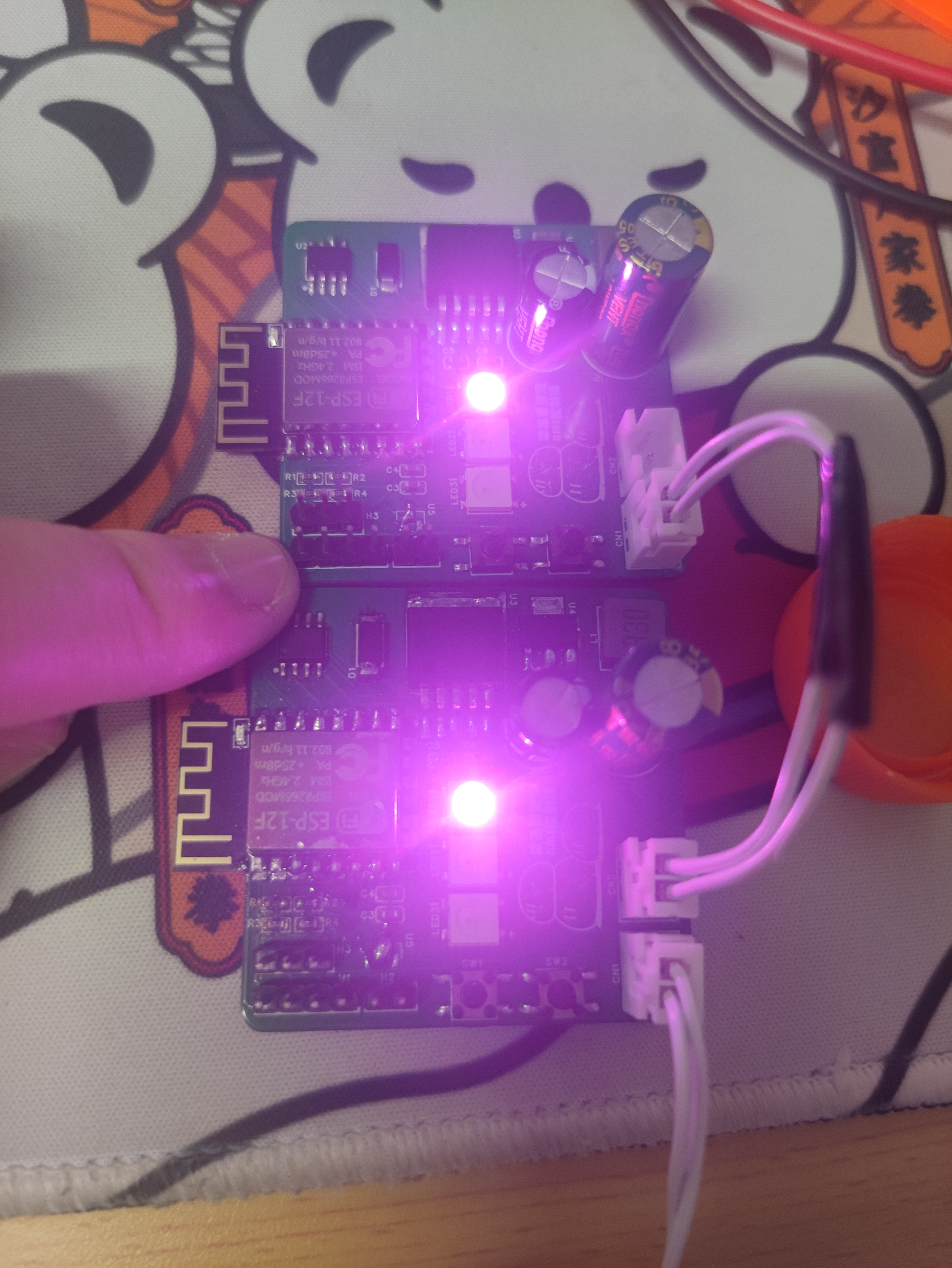
APAMS Control Panel
AP-AMS control board
An updated version is available. Please visit https://oshwhub.com/applenana/ap-ams-control-panel-30 to view
the integrated 5V/3.3V step-down motor control, enabling servo control, motor control, and LED control. Daisy-chain power supply is possible; please
pay attention to the encapsulation!
Quantity
Name
Corresponding Tag
Package
1
1
680uF
C1
CAP-TH_BD10.0-P5.00-D1.0-FD
2
1
220uF
C2
CAP-TH_BD8.0-P3.50-D0.6-FD
3
1
10uF
C3
C0603
4
4
100nF(0.1uF)
C4, C5, C6, C7
C0603
5
2
xh2.54 socket
CN1, CN2
CONN-TH_2P-P2.50_HX25003-2A
6
1
1N5824 SMD Schottky diode
D1
DO-214AC_L4.3-W2.7-LS5.2-RD
7
1
4pin header
H1
HDR-TH_4P-P2.54-VM
8
3
2pin
H2
HDR-TH_2P-P2.54-VM
9
1
3pin
H3
HDR-TH_3P-P2.54-VM-1
10
1
33uH
L1
IND-SMD_L7.1-W6.6_MJC-0603T
11
3
5050-WS2812B
LED1, LED2, LED3
LED-SMD_4P-L5.0-W5.0-BL_XL-5050RGBC 12
5
10K
R1
, R2, R3, R4, R6
R0603
13
1
300K
R5
R0603
14
2
4.5mm SMD Microswitches
SW1, SW2
SW-SMD_4P-L4.5-W4.5-P3.00-LS7.0
15
1
esp12f
U1
WIFIM-SMD_ESP-12F-ESP8266MOD
16
1
TC118S
U2
SOP-8_L4.9-W3.9-P1.27-LS6.0-BL
17
1
LM2596S-5.0
U3
TO-263-5_L10.2-W8.9-P1.70-BR
18
1
AMS1117-3.3
U4
SOT-223-3_L6.5-W3.4-P2.30-LS7.0-BR
PDF_APAMS Control Panel.zip
Altium_APAMS Control Board.zip
PADS_APAMS Control Board.zip
BOM_APAMS Control Board.xlsx
94110
Low-cost expansion based on HS8836A
This design is a simple expansion dock based on the HS8836A, using a one-to-four structure to add three external ports for the laptop.
The HS8836A is a high-speed USB 2.0 hub controller chip with an embedded RISC-like processor for operating internal control/status registers and responding to commands from the USB host. The HS8836A is designed to minimize external components and BOM costs, and its optimized pin layout supports single-sided and cross-line-free layouts, effectively reducing production costs.
This hub is fully compatible with the USB 2.0 standard and backward compatible with the USB 1.1 standard.
BOM_Extension Dock.csv
Dock.jpg
PDF_Low-Cost Extension Based on HS8836A.zip
Altium - Low-Cost Extension Based on HS8836A.zip
PADS_Low-Cost Extension Based on HS8836A.zip
BOM_Low-Cost Extension Based on HS8836A.xlsx
94111
5V/3A Type-C female to male adapter supports USB 2.0
5V/3A Type-C female to male jack, designed to provide compatibility support for low-power devices that omit CC Rp Rd resistors and do not support C2C data lines.
This 5V/3A Type-C female-to-male connector provides compatibility for low-power devices that omit the CC, Rp, and Rd resistors and do not support C2C data lines.
It also connects D+ and D- to support the USB 2.0 communication protocol, allowing some devices requiring communication to use it.
The principle is simple: adding Rp and Rd resistors replaces the low-power devices for communication with the other end.
The housing design and 3D printing files are attached. Note that a pause layer needs to be added when printing the housing for placement on the PCB.
USB Type-C 5V3A.f3d
USB Type-C 5V3A Body A.stl
USB Type-C 5V3A Body B.stl
PDF_5V-3A Type-C Female to Male USB 2.0 Support Package.zip
Altium_5V_3A Type-C Female to Male USB 2.0 Support Package.zip
PADS_5V_3A Type-C Female to Male USB 2.0 Support Package.zip
BOM_5V_3A Type-C Female to Male USB 2.0 Support.xlsx
94113
Adjustable power supply
It can operate continuously at high power for extended periods.
The FCP fast-charging buck module supports QC2.0 3.0.
It can operate continuously at high power for extended periods.
The FCP fast charging step-down module supports QC2.0 and 3.0,
and is compatible with Apple (no pop-up windows, faster than the original charger), Xiaomi, Samsung, Huawei, OPPO, VIVO, and 90% of mainstream tablets and mobile phones on the market.
The DC input interface is 5.5×2.5mm, and the output interface has a maximum voltage of 6-36V, with a single port power of 24W (output power depends on your power supply). Each port supports fast charging without current splitting or interference, and will not damage your phone or cause pop-up windows.
Only one idle 6-36V DC input port is required.
PDF_Adjustable Power.zip
Altium_AdjustablePower.zip
PADS_Adjustable Power.zip
BOM_Adjustable Power Supply.xlsx
94114
Simple radio
Do you remember those summer evenings when you sat in the yard listening to the radio with your grandparents and other relatives, enjoying the cool evening air? Do you remember the little loudspeaker programs that aired on those summer evenings?
Project Introduction:
This is a simple FM radio. In the summers of my childhood, I loved listening to the radio in my grandfather's room. Tick-tock, tick-tock, it's 8 PM Beijing time, China National Radio, Voice of China, and then tick-tock, kids, the little loudspeaker is broadcasting.
Many years have passed, and I can't remember which sister was the host, but I cherish the memory of my grandfather and my childhood. This summer-themed activity involves making a simple radio to reminisce about my childhood. I am also an amateur radio enthusiast. Amateur radio plays a vital role in countless disaster relief efforts, and this project also pays tribute to the intelligence workers who sacrificed their lives during wartime, and to the ever-burning radio waves.
This project includes an ESP32 version, with the open-source link at https://oshwhub.com/laobainb/jian-yi-shou-yin-ji-esp32-ban.
The radio chip chosen is the DRA5807m, a new generation microcontroller-based FM stereo tuner with minimal external components. It uses I²C for communication with the microcontroller
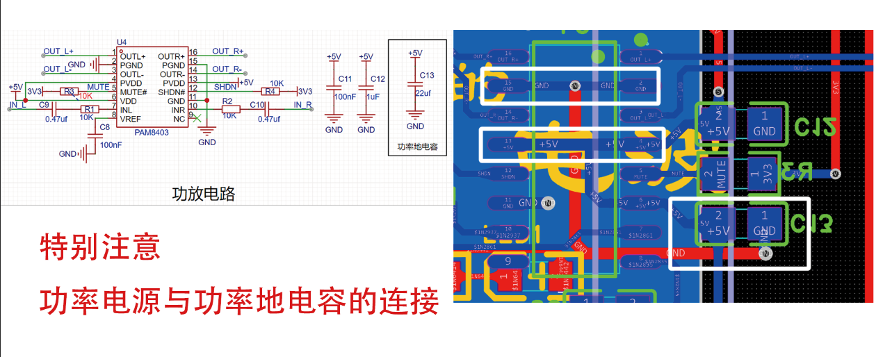
. The audio amplifier chosen is the PAM8403, a stereo power amplifier that provides Class AB power amplifier performance with Class D amplifier effects. This requires very few external components, saving PCB space and reducing design costs.
The power management uses the IP5306, a multi-functional power management SOC integrating a boost converter, lithium battery charging management, and battery level indicator. It also requires few external components, using only one inductor to achieve buck and boost functions. The synchronous boost system provides a maximum output current of 2.4A with a conversion efficiency of up to 92%. Under no-load conditions, it automatically enters sleep mode, with the quiescent current dropping to 100uA.
Cost Estimate (Ultimate Freebie):
JLCPCB's
electronic consumables
include main components such as battery management chips, audio power amplifier chips, and speakers, as well as peripheral components such as capacitors and resistors. The promotional coupon provided a perfect amount for the consumables, plus a free shipping coupon. Therefore, the consumables were free and shipping was included. The
3D shell
had multiple versions, so two sets were made. The promotional coupon made it free, plus a 5 yuan shipping fee. Alipay payment incurred a 0.02 yuan handling fee. The
panel
also had a promotional coupon, was free, and was ordered together with the consumables, so shipping was also free. Furthermore, the panel supplier, Mr. Huang, was extremely conscientious and responsible. Because the gap between the speaker grille on the first version of the panel was too small, it could cause it to melt during production. Engineer Huang kept checking and following up, which was very nice.

The PCB
was free, and the RDA580 (
which JLCPCB didn't have) was also included
with free shipping. Screws, nuts, and antennas were all purchased from Taobao. With various discounts, it was a great deal; I practically got a steal! Haha~~
The
basic principle of a radio is that the radio station modulates the audio signal → transmits it through the antenna → it propagates in space → it is received by the radio → it is demodulated and played through the speaker.
Modulation is
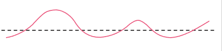
because the sound we usually hear is a low-frequency signal, but low-frequency signals have a very short propagation distance. If we want the signal to travel further, we need a higher signal, so we superimpose the sound signal (approximately several hundred Hz) onto a high-frequency signal (possibly several hundred MHz). Then, transmission occurs. Modulation methods include amplitude modulation (AM) and frequency
modulation
( FM).
FM
modulation has a constant amplitude, but the frequency changes with the low-frequency signal.
AM modulation has
a constant frequency, but the amplitude changes with the low-frequency signal.
A diagram illustrates
the sound signal
: high-frequency signal (equivalent to a carrier)

→ FM

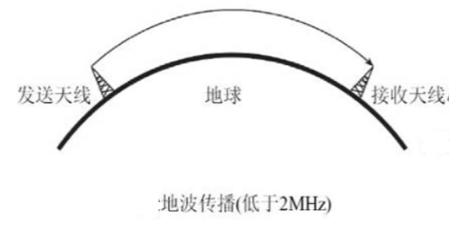
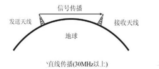
→ AM transmission. Propagation

methods include skywave (radio waves reflected by the ionosphere and returning to the ground), groundwave (radio waves propagating along the Earth's surface), and spacewave (radio waves propagating in a straight line from the transmitter to the receiver), etc. Demodulation hardware explanation : RDA5807M . The RDA5807M series is a new generation of single -chip microcontroller broadcast FM stereo tuners, featuring a fully integrated synthesizer, intermediate frequency selectivity, RDS/RBDS, and MPX decoders. The tuner uses CMOS technology, supports multiple interfaces, and requires minimal external components. All of these make it ideal for portable devices. The RDA5807M series has a powerful low-IF digital audio processor, which ensures optimal sound quality under various receiving conditions. The RDA5807M series supports a frequency range from 50MHz to 115MHz. Pins 1, 3, and 8 are GND (ground). Pin 7 is for power supply; according to the datasheet, the supply voltage is 2.7V~3.3V. Use a 47uF electrolytic capacitor and a 100nF surface-mount capacitor to filter out low-frequency and high-frequency noise from the power supply, respectively. Pin 6 connects to the crystal oscillator; according to the datasheet, select a 32.768kHz capacitor and include ground in the PCB design. Avoid copper pouring in prohibited areas, and ensure that power lines are not used on any layers in the crystal oscillator area. Pins 4 and 5 are the RDA5807M's I²C communication pins, connected to the core board. Consult the datasheet to check which I²C-supported I/O ports are available. When using I²C, you can choose between automatic I²C and hardware I²C. To facilitate later development, we selected pins (PA0, PA1) with I²C multiplexing function, thus providing hardware I²C support. If we used software I²C, it would simply be used as a copper-plated I/O port. Pins 9 and 10 are audio output interfaces, each connected to the PAM8403 power amplifier chip via a 100nF coupling capacitor. The PAM8403 is an excellent audio power amplifier integrated IC. It can provide 3W of power with an efficiency exceeding 85%, and also features system shutdown and mute control functions. Its special circuit architecture enhances noise immunity and reduces RF interference. According to the chip datasheet (see attachment), pin 6 is the power supply pin, using 5V; pin 11 is ground, using 100nF and 1uF capacitors to filter out high-frequency and low-frequency noise; pins 4 and 13 are power supply pins; and pins 2 and 15 are power ground pins. Considering the low power consumption, no isolation from the analog signal was implemented. However, to prevent ground shift, a 22uF capacitor was used. This capacitor should be placed as close as possible to the power supply and power ground. (If there is a ground shift in the circuit, the original 5V voltage may not be 5V anymore, but will become another voltage. This is because the 5V voltage is relative to the GND ground line (0V). If the ground shift causes the GND ground line to rise from 0V to 1V, then the previous 5V (5V-0V=5V) voltage becomes 4V (5V-1V=4V)).


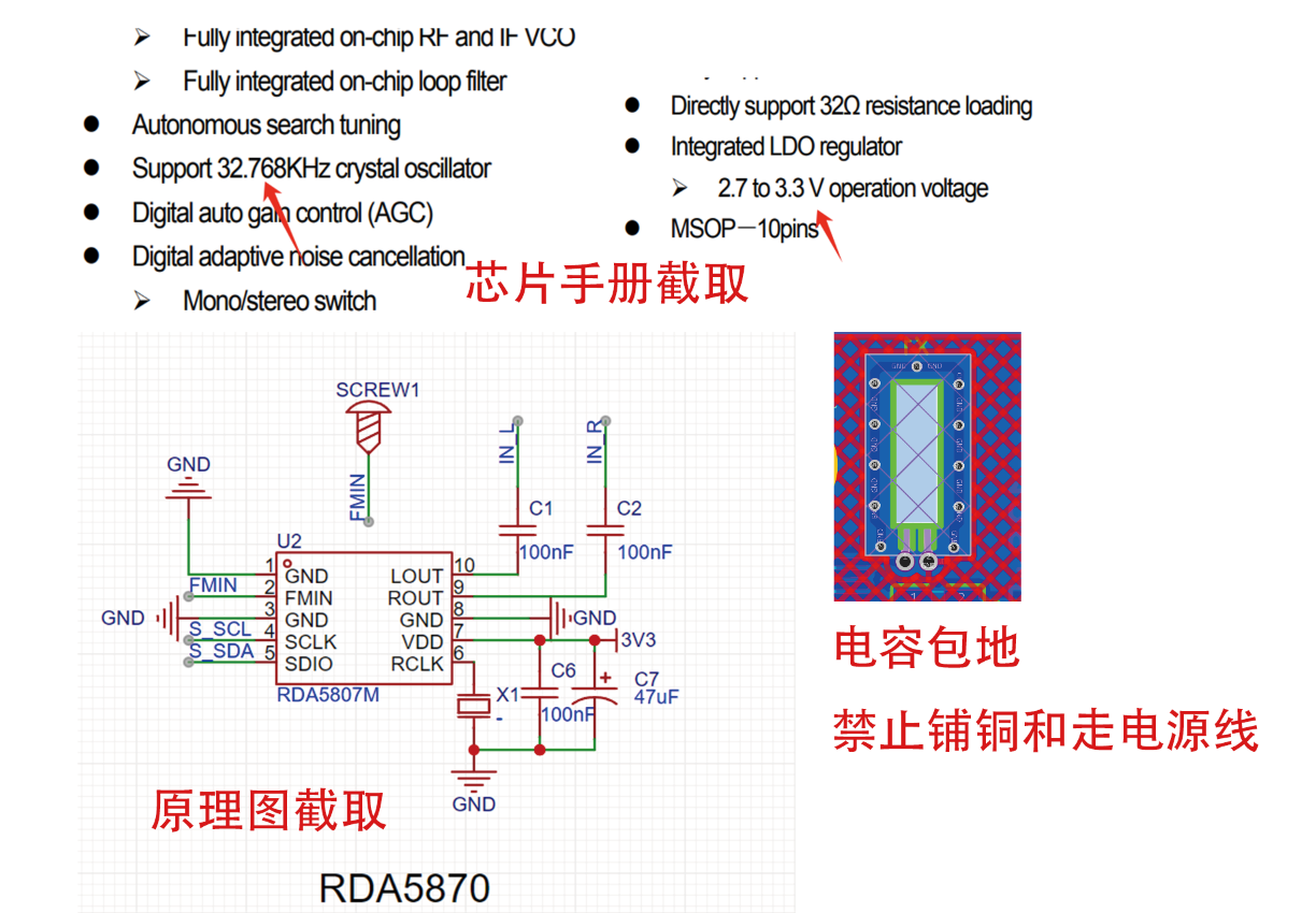
Pin 8 is the internal reference source, connected to GND via a 100nF bypass capacitor.
Pin 10 is the input for the left and right channels respectively, connected in series with a 10k~20k resistor and a 0.47uf capacitor according to the chip datasheet.
Pins 1, 3, 16, and 14 are the positive and negative terminals for the left and right channels respectively, directly connected to the speaker (speaker interface).
Pin 5 is the mute control input, active low, pulled high by a 10k pull-up resistor and connected to the microcontroller core board for later program control.
Pin 12 is the system shutdown control, active low, also pulled high by a 10k pull-up resistor and connected to the microcontroller core board for later program control.
Pin 9 is a no-go pin, left floating.
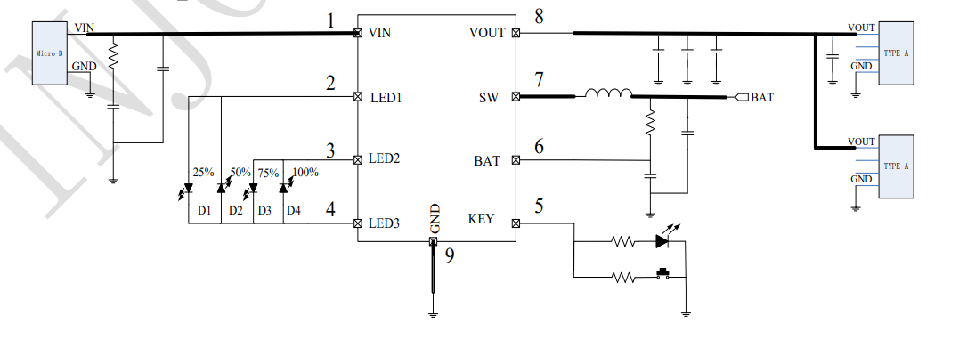
Battery management
uses IP5306 for charge/discharge management; the external circuit is simple and easy to control.
Pin 1 is the power input, connected to the Type-C input.
Pin 8 is the output, supplying power to the entire circuit
. Pins 2, 3, and 4 connect to the positive terminal of the battery. Pins 4 connect to the
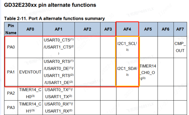
power indicator LED. The RDA5807 supports I²C communication, which can be achieved using both software and hardware I²C. For code simplicity (I'm too lazy to write complex code to handle timing signals, data signals, error detection, signal conflicts, etc.), and since this is a radio, we will use hardware I²C. Referring to the chip datasheet, we will use PA0 and PA1. Define variables and crystal oscillator #ifndef __RDA5807_H // Positive and negative feedback #define ACK 0 #define NACK 1 // Boolean variable #define TRUE 1 #define FALSE 0 // Read/write flag #define READ 1 #define WRITE 0 #define ADRW 0x20 // RDA5807P write register address #define ADRR 0x21 // RDA5807P read register address /* * This radio uses the RDA5807M module, which uses a 32.168KHz crystal oscillator. If using other crystal oscillators, use different macro definitions according to the frequency */ //#define _SHARE_CRYSTAL_24MHz_ // 24MHz crystal oscillator //#define _SHARE_CRYSTAL_12MHz_ // 12MHz crystal oscillator #define _SHARE_CRYSTAL_32KHz_ // 32KHz crystal oscillator //#define _FM_STEP_50K_ //50K steps. Then, configure the I²C. Different manufacturers have different configuration methods, but the process is the same: enable the clock, configure the pin multiplexing and function of SCL and SDA, configure the IC address, and enable the response. This project is applicable to GD32, CW32, and STM32. Different main controllers have different function libraries and initialization methods, but the way to manage RDA5807 is the same. Setting the frequency void RDA5807_SetFreq(short int curFreq) { unsigned short int curChan ; curChan = RDA5807_FreqToChan(curFreq); //SetNoMute RDA5807_REGW[0] |= 1 << 7; RDA5807_REGW[2] = curChan >> 2; RDA5807_REGW[3] = (((curChan & 0x0003) << 6) | 0x10) | (RDA5807_REGW[3] & 0x0f); OperationRDAFM_2w(WRITE, &(RDA5807_REGW[0]), 4); delay_ms(50); } Read frequency unsigned short int RDA5807_RegToInt(void) { unsigned char RDA5807_REGR[10] = {0x0}; unsigned short int temp; OperationRDAFM_2w(READ, (unsigned char *)&RDA5807_REGR[0], 10); temp = RDA5807_REGR[0]; temp = ((temp << 8) | RDA5807_REGR[1]); temp = (temp & 0x03FF) * 10 + 8700; return temp; } Set mute void RDA5807_SetMute(int mute) { if(mute == TRUE){ RDA5807_REGW[0] &= ~(1<<6);//Enable bit 14 of register 02H to be 0, enable mute } else{ RDA5807_REGW[0] |= 1<<6; }
OperationRDAFM_2w(WRITE, &(RDA5807_REGW[0]), 2);
delay_ms(50); //Deadly 50 ms
}
In conclusion
, I want to say to everyone that it's over. I don't know what to say, but the sense of ritual in summarizing is still necessary. Let's pay tribute again to the never-ending radio waves. This is BG5AWB
WeChat_20240618002149.mp4
WeChat_20240618002141.mp4
PDF_Simple Radio.zip
Altium_Simple Radio.zip
PADS_Simple Radio.zip
BOM_Simple Radio.xlsx
94115
electronic


 京公网安备 11010802033920号

 MDF76KBW-30S-1H


