I. Introduction to
the 2023 National Electronic Design Contest, Problem J: [Automatic Circuit Fault Detection System]
This work entered the national finals, but was stopped at the second level due to a program bug
. This bug has now been fixed.
This work uses common components and fulfills all the requirements of the problem. Power supply only requires a Type-C USB connection, making it low-cost to manufacture and suitable for replication and reproduction.
II. Problem Requirements
Basic Requirements:
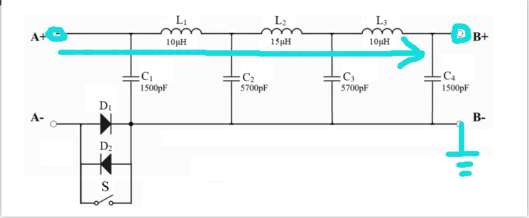
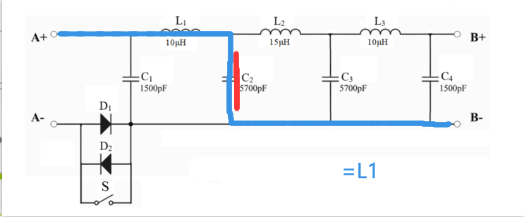
In Figure 1, switch S is closed. Only one inductor or capacitor is faulty in the circuit network.
After pressing the start button, the system automatically detects and displays the faulty component number and fault type (open circuit or short circuit).
Advanced Section:
Switch S is open.
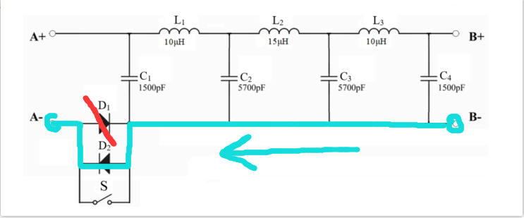
One diode in the circuit network has an open circuit fault. Simultaneously, one inductor or capacitor is faulty. After pressing the start button, the system automatically detects and displays the faulty component number and fault type.
The circuit network may be fault-free, or only one inductor or capacitor is faulty, or one diode has an open circuit fault while another inductor or capacitor is faulty.
After pressing the start button, the system automatically detects and displays the system status (whether there is a fault), and the faulty component number and fault type when a fault is present.
Other.
III. Design Summary:
The overall structure is simple, using common components, and fulfilling the requirements of the problem at low cost.
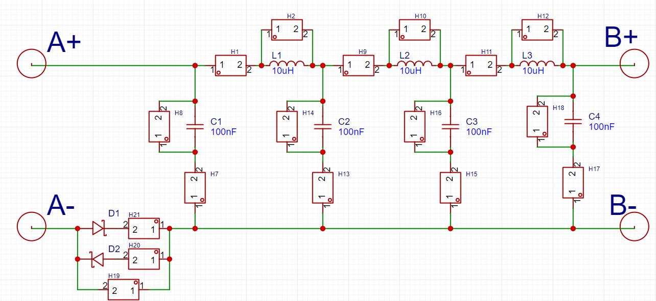
This system uses the STM32F103 as the control core of the entire design. The entire system consists of the main control chip system circuit, signal buffer circuit, ADC sampling circuit, relay control multiplexing circuit, capacitance measurement circuit, resistance measurement circuit, keypad circuit, and display circuit.
Two measurement methods are combined in the design. The first is the resonance method, where a 720kHz square wave signal is generated by the microcontroller's timer and sent to the circuit under test. ADC sampling is performed at the output, i.e., the digital value of the output voltage of the sampling circuit. Repeated testing is conducted to establish a sample model, which is then compared and judged in actual testing.
The second is the measurement method, which substitutes the corresponding circuit under test into the capacitance and inductance measurement circuits to compare the values of some fault points, judging and displaying the fault location and type of the circuit under test.
Combining these two detection methods, the fault location and type of the circuit under test are accurately determined and displayed. After multiple debugging sessions, the expected functions of the measurement system are achieved.
It is recommended to use surface-mount capacitors (accuracy: ±10%) and I-type inductors (accuracy: ±10%) connected in series and parallel to meet the requirements of the problem.
Since there are inherent errors in the manufacturing of capacitors and inductors, the frequency of the injected square wave signal needs to be adjusted according to your own board, approximately 600kHz~900kHz. The output signal will differ at different frequencies. Multiple frequencies can be used for multiple measurements to increase accuracy.
The measurement of capacitors and inductors does not require deducing the exact value; only the approximate values under various conditions need to be compared to infer the fault location and type.
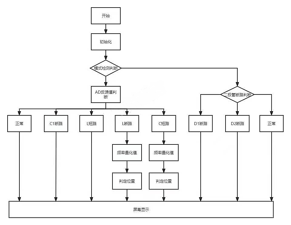
Fourth, the measurement flowchart:

First, inject a 720kHz square wave through A+, output through B+, ground through B-, buffer the signal, and then sample it with the ADC. By comparing the peak-to-peak values of the signal, a short circuit in the inductor and an open circuit in the capacitor can be determined.
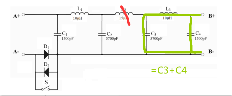
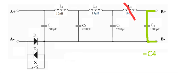
If the ADC feedback is 4096, it indicates no signal at the B+ terminal, and the capacitance measurement stage begins: turn off signal generation, measure the total capacitance from B+ to B-, and deduce the location of the open circuit in the inductor.

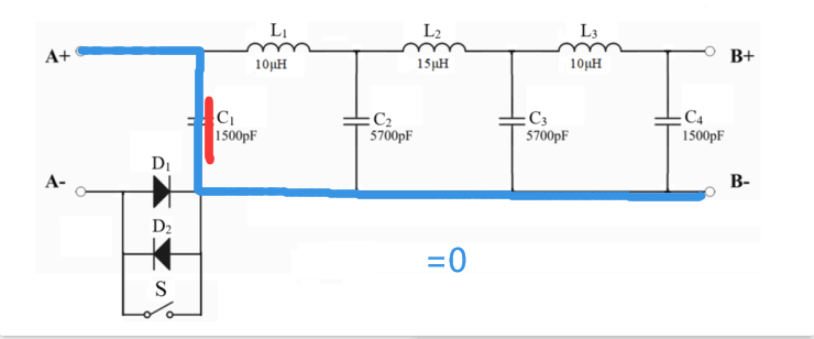
If the ADC feedback is 0, it indicates that B+ is grounded, and the inductance measurement stage begins: Signal generation is turned off, A+ is connected to 3.3V, and B- is connected to the inductance measurement circuit. By comparing the inductance values, the location of the capacitor open circuit can be deduced.


For diode testing: Signal generation is turned off, A- is pulled high, and the B- level is measured to infer whether D1 is faulty; then B- is pulled high again, and the A- level is measured to infer whether D2 is faulty.

Fifth, Problem Analysis:
The problem is an automatic fault detection system for equivalent network circuits of signal transmission lines, which must be related to signals. According to the equivalent model, it is highly likely related to parameters such as impedance.
By observing the circuit diagram, multiple measurements of different parameters can be used to infer the fault location and type.
Another method is to measure the voltage difference and current phase, which should be feasible, but I have not verified it.
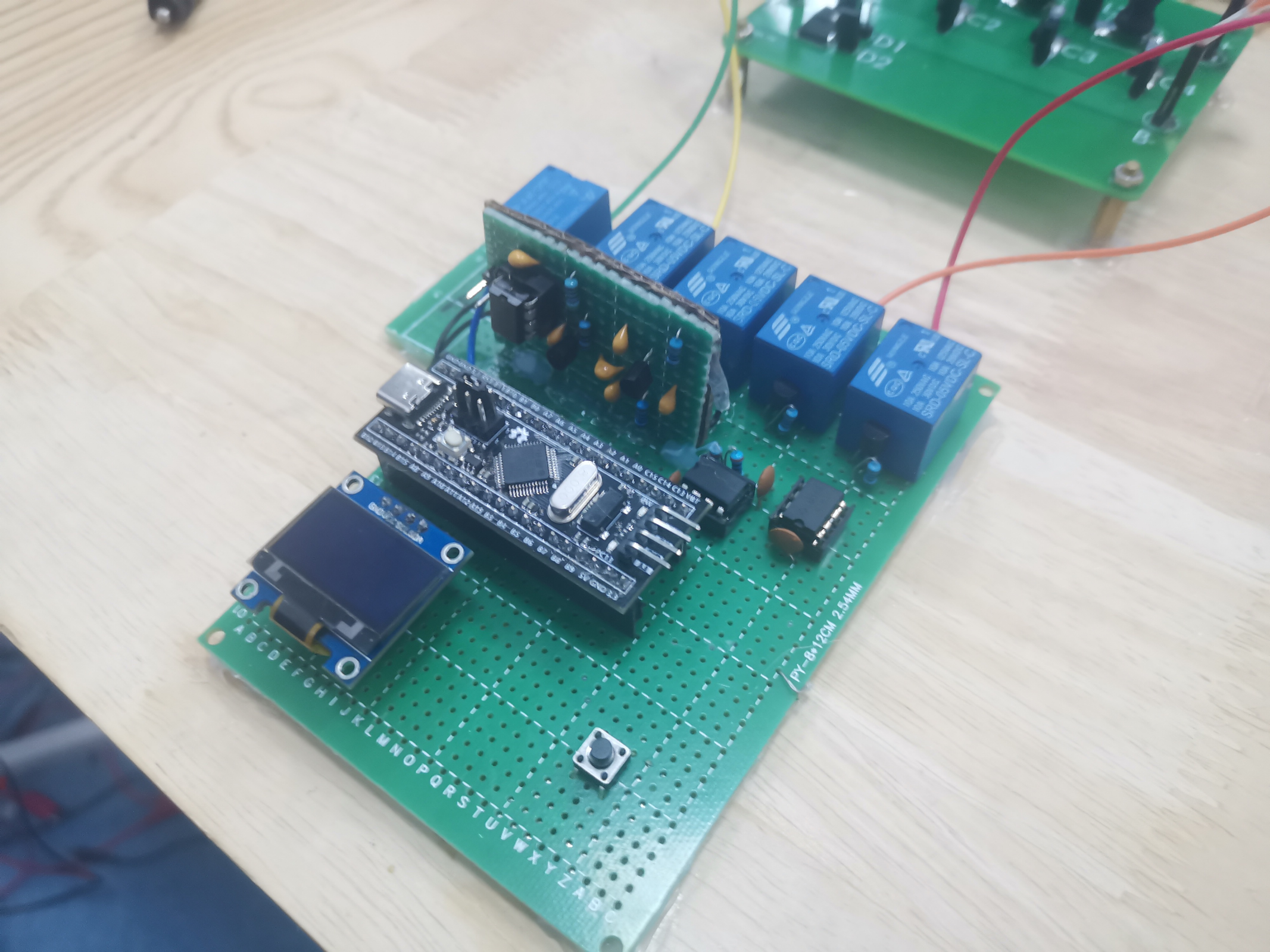
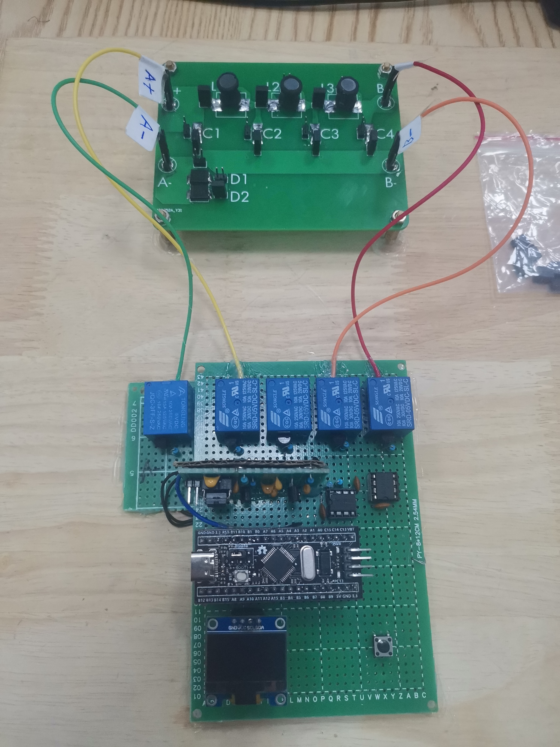
Sixth, Hardware Circuit Composition

: The measurement system mainly consists of a microcontroller minimum system, a multiplexing circuit, a capacitance measurement circuit, and a capacitance measurement circuit.
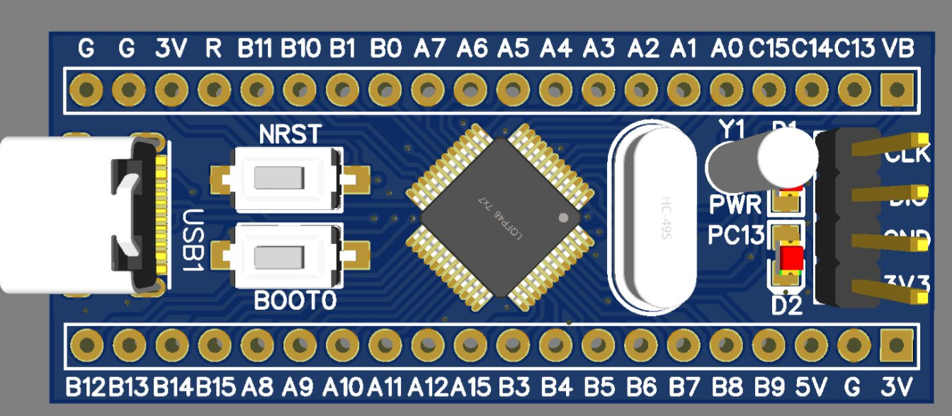
The microcontroller minimum system is a BluePill board
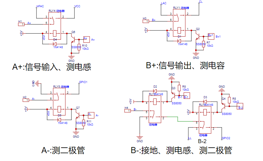
that uses relays to implement multiplexing
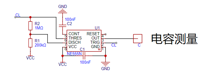
and a multivibrator NE555. The frequency of the output square wave is used to infer the capacitance of the line.
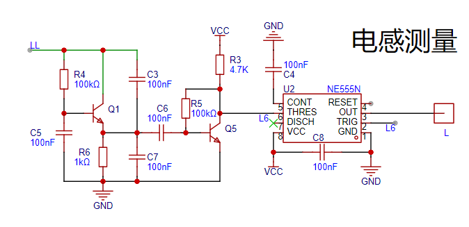
Using a three-point resonant circuit, the NE555 is used as a Schmitt trigger, and the output frequency is used to inversely determine the inductor value.
Seven, Program Flowchart; Eight
, Physical Demonstration

; Nine, Attachments
: Attachment 1: Program Source Code (Keil with STM32CubeMX); Attachment 2: Demo Video.


 京公网安备 11010802033920号

 MJN1C
MJN1C


