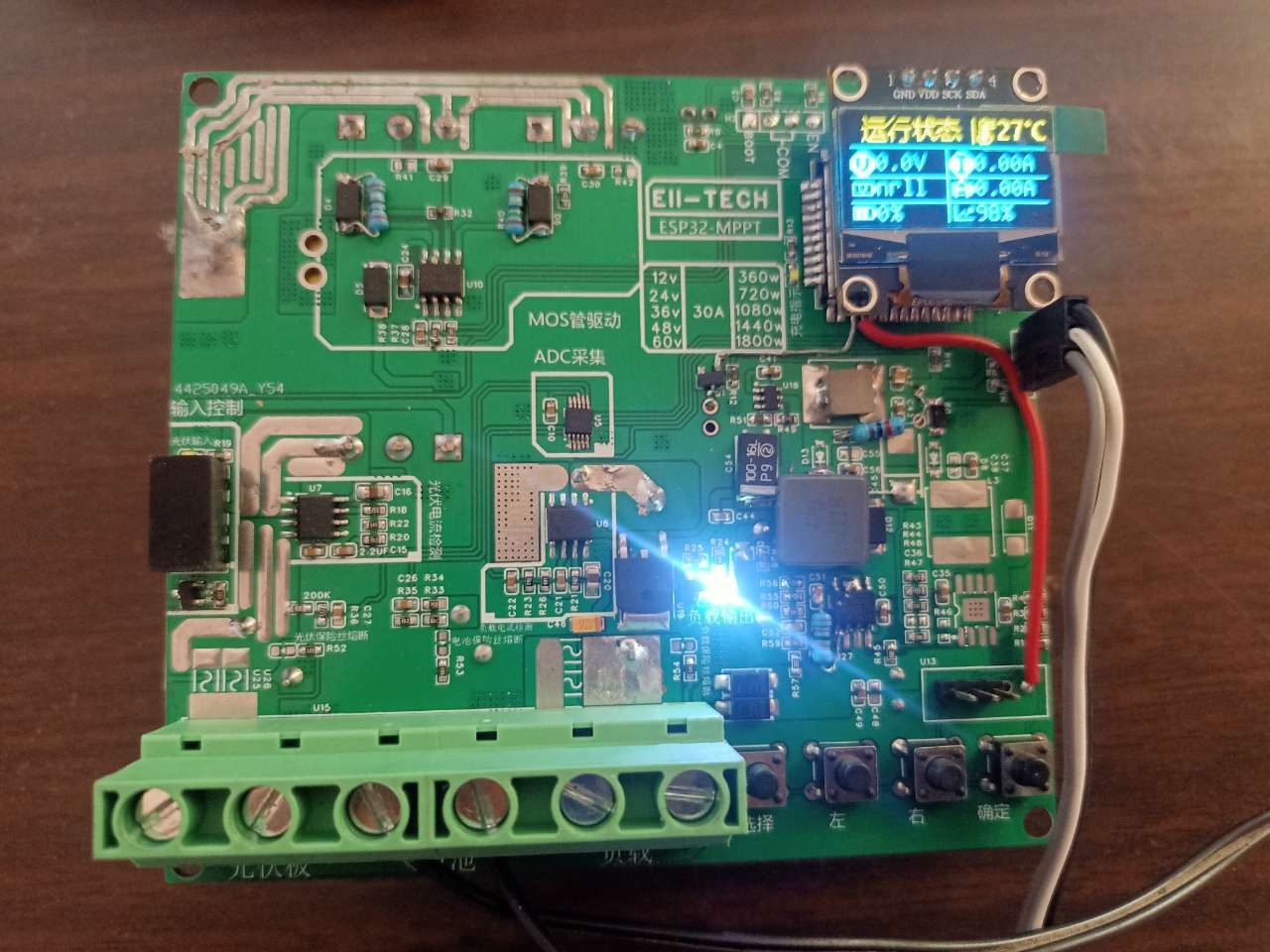
EII-TECH ESP32 MPPT-CONTROLLER
========================================================
Using ESP32-S General Purpose Wi-Fi MCU The module
has a 7-80V input voltage range
, a 30A charging current (adjustable),
and a maximum controllable load current of 30A.
It can be managed via a web page
and remotely viewed through Blinker. The controller can be mapped to the public network for management.
Important Note:
There is a problem with the optocoupler in this project; it is recommended to short it first.
I am currently a high school student, so project updates and responses may not be timely. Please understand
. Note:
This project is for DIY and learning purposes only.
This project is modified from https://oshwhub.com/lhg888888/ce-shi-tai-yang-neng-kong-zhi-qi-v1-3.
This project is under GPL 3.0 (free to use, copy, modify, and distribute protected programs, but the source code must be provided when distributing).
Performance Parameters:
MOSFET version,
Relay version
, Input Voltage:
7-80V,
Operating Current:
30A,
Load Control Current:
15A
/30A
, Topology:
Synchronous Buck, BUCK
PWM, Frequency:
39.0625kHz
. Web Management:

Blinker, Standby Power Consumption (Relay Action).

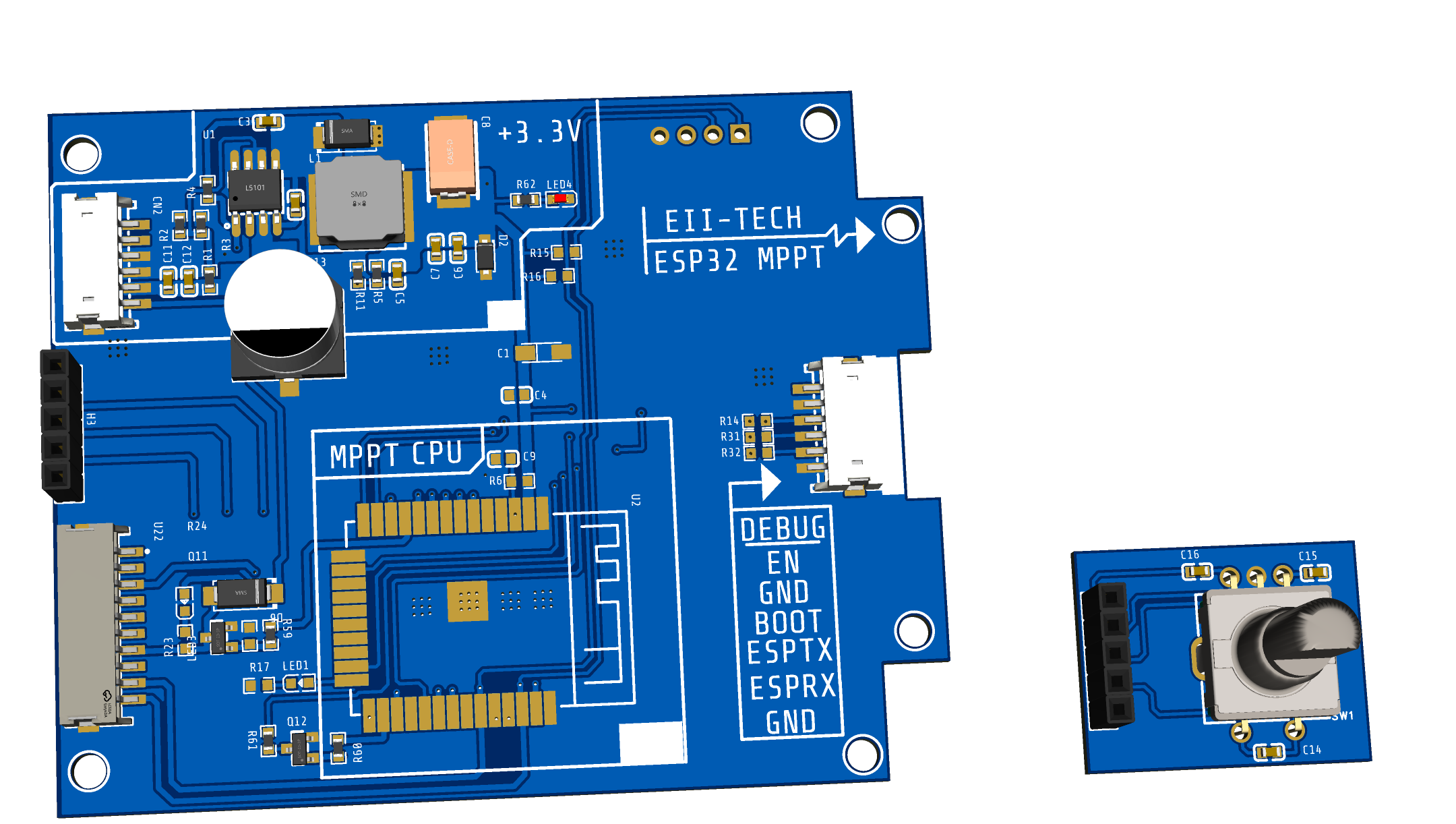
I. Expansion panel
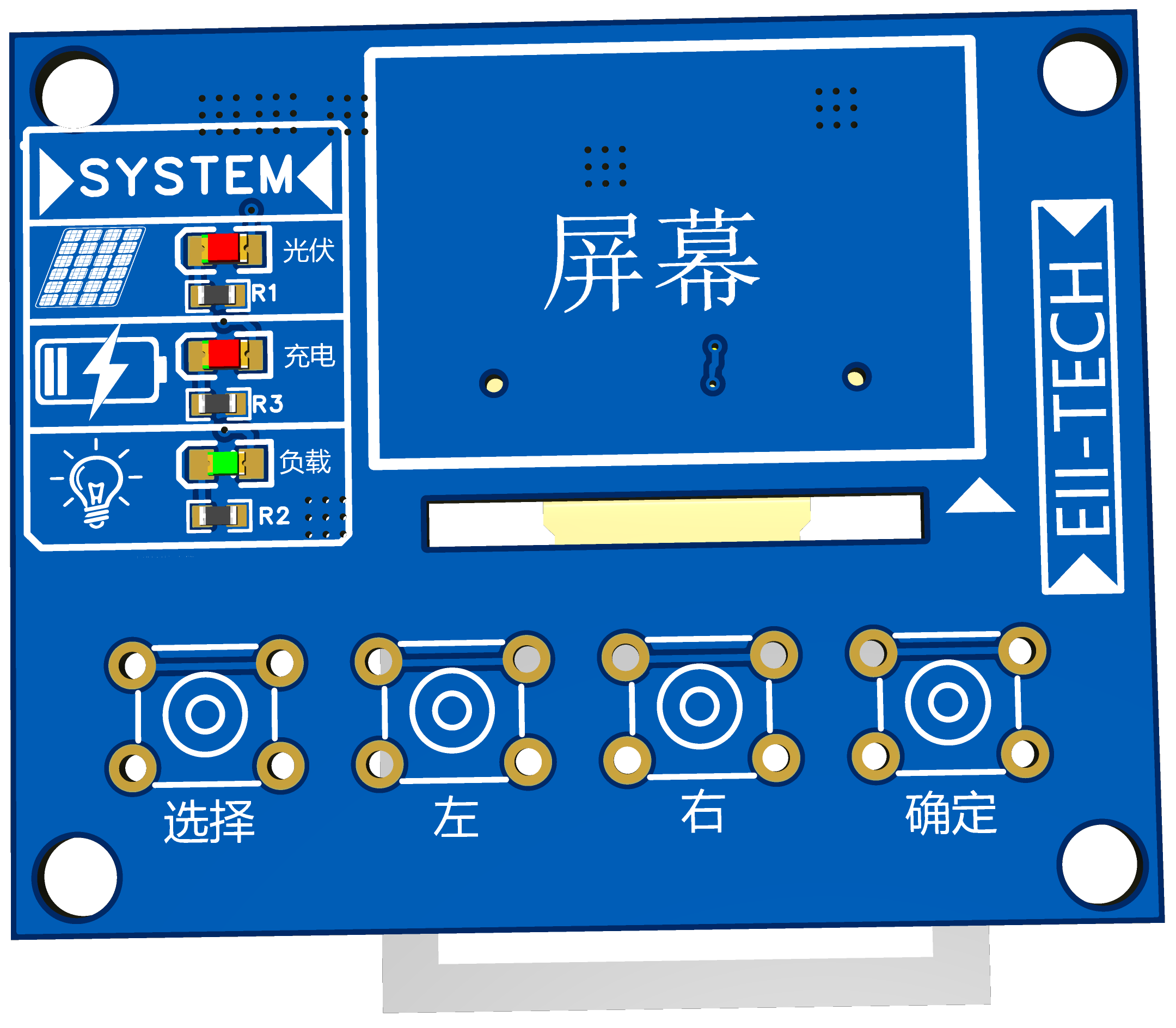
for easy installation. The casing uses an 11-pin flexible flat cable for connection.
I. Update Log:
Relay version removed one 12V power supply;
systems below 14V cannot start. Modified the 12V power chip voltage divider to solve the problem.
Used PC817 optocoupler isolation. IR2104 and ESP32 to avoid burning out ESP32.
Replaced the MOS controlling the relay with an NPN transistor.
Completed expansion panel
update and optimization. Power board and control board (untested, do not use yet!!!).
I. Construction Notes:
I. Component Purchase:
ACS712, IR2104, IRFP4568PBF, and power chip must be genuine.
Counterfeit ACS712 may explode if the current exceeds 10A.
Counterfeit IR2104 will break down under high photovoltaic voltage. (There are many counterfeit IR2104s; if you cannot guarantee genuine products, you can use EG2104S.) D8 replaced with FR107)
Fake IRFP4568PBF high power is prone to explosion (if IRFP4568PBF is too expensive and photovoltaic voltage is not high, HY4008w can be used instead).
Fake ADS1015 will cause self-test failure and the system will not start.
The requirements for the resistor and capacitor section are not high, accuracy ±5% (u18 C33 C25 C10 C11 C12 withstand voltage must reach 120V).
IPCB soldering:
The component density of this PCB is not high, so it can be soldered with a soldering iron or solder paste. However, pay attention to the amount of solder paste on the ESP32 pad. Otherwise, too much solder ball will not flow into the pad and will remain at the bottom of the ESP32, causing a short circuit. It is very troublesome to resolder the ESP32. The pins of ADS1015 are dense and bridging is possible. When soldering, you can add more flux. Drag the solder
and mark the flying wire. The pad must be connected, otherwise the board will be easily burned.
After soldering, you can use a mobile phone camera to check the ESP32. Is the ADS1015 bridging or cold solder
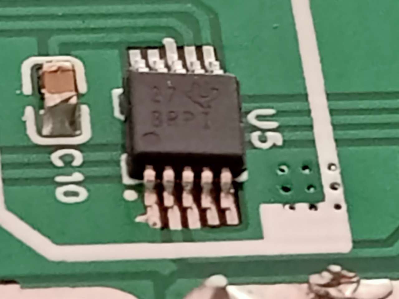
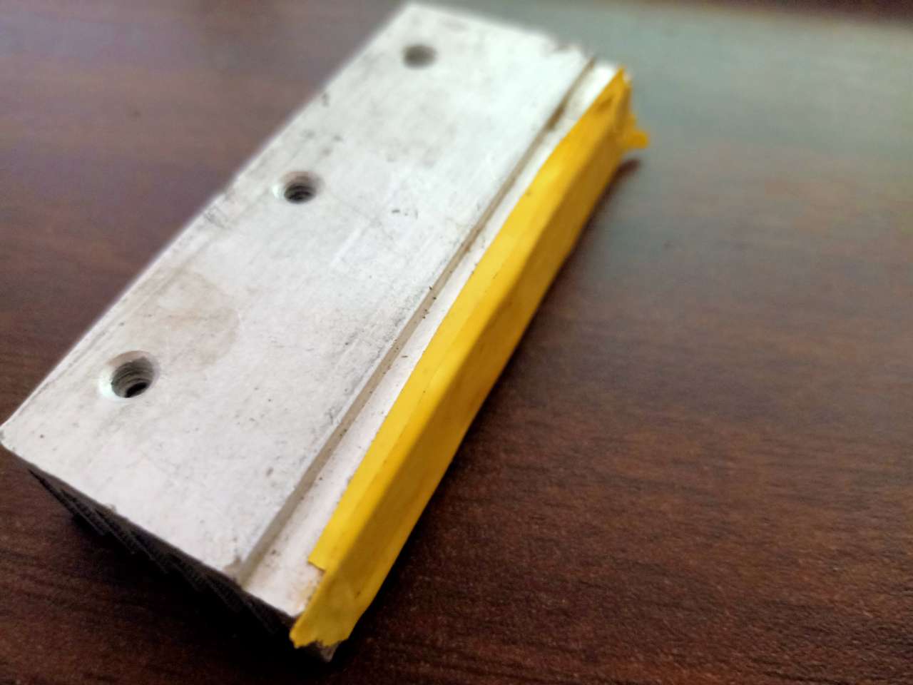
joint? The heatsink
must be insulated. Insulating tape must be applied to the bottom of the heatsink. Insulating pads are needed for the power transistors.
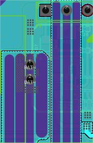
After installation, measure as shown in the diagram below. Pour copper (do not short-circuit) and fix the temperature sensor.
The fan uses a 3cm 12V fan with a current not exceeding 0.4A
. The program download,
flashing, and calibration tutorial is not yet finished; it will be added later.

The first flashing requires restoring the default factory settings. Default WiFi password: 123456. Web management address: espmppt.com
. Common problems and solutions (continuously updated, additions welcome). Possible causes
and solutions: System repeatedly restarts; ADC cold solder joint or bridging; bought a fake ADC ; SCL/SDA short circuit to ground; 3.3V insufficient power supply ; resolder the ADC ; replace with a genuine product ; troubleshoot short circuit faults (focus on checking the bottom layer of ESP32; the probability of a short circuit is extremely small. If removing ESP32 and ADC still results in a short circuit, the board must be moved). Check the power supply; 3.3V; DCDC burnt out low-end MOS; 1. Set the charging voltage to be less than the battery voltage; 2. MOS quality issues : 1. Set the correct charging voltage; 2. Replace with a genuine product. Our discussion group: 771475026. Special thanks to Lan Hong and many netizens for providing modification suggestions and optimizing the version.


 京公网安备 11010802033920号

 240-0322-9PCC6J7-18S1


