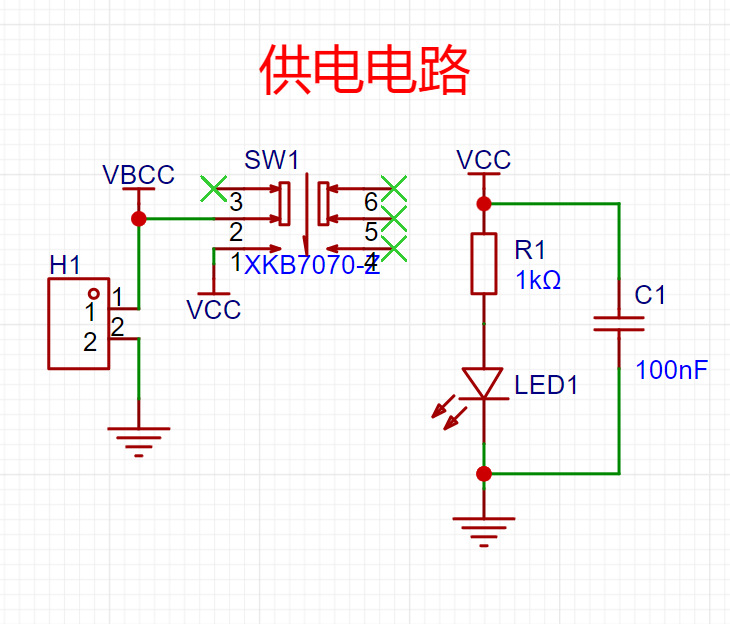
 A self-locking switch is used: when the switch is pressed, pins 1 and 2 are activated, the LED lights up, and the circuit begins to work.
  L1 and L2 are coils drawn on the PCB, and the three transistors correspond to three functions: an oscillation circuit (9018), a detection circuit (9015), and an alarm circuit (9012).
 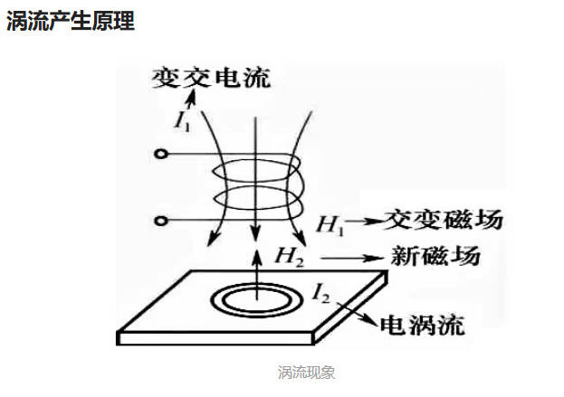 When no metal is near, there is an LC oscillation (9018). When a metal object is near, eddy currents are generated inside the metal, causing the LC oscillator to lose its oscillation signal, thus determining the presence of metal. The detection circuit composed of 9015 captures this signal. When metal approaches, the base of 9012 goes low, the transistor conducts, and the buzzer sounds.
 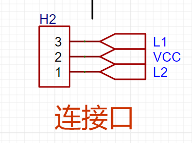 the PCB using pin headers
 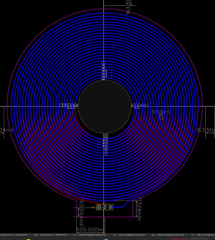 , use tools and lines to make it look better; this may strain your eyes (it's recommended to drink some water to relax).
All reference designs on this site are sourced from major semiconductor manufacturers or collected online for learning and research. The copyright belongs to the semiconductor manufacturer or the original author. If you believe that the reference design of this site infringes upon your relevant rights and interests, please send us a rights notice. As a neutral platform service provider, we will take measures to delete the relevant content in accordance with relevant laws after receiving the relevant notice from the rights holder. Please send relevant notifications to email: bbs_service@eeworld.com.cn.
It is your responsibility to test the circuit yourself and determine its suitability for you. EEWorld will not be liable for direct, indirect, special, incidental, consequential or punitive damages arising from any cause or anything connected to any reference design used.
Supported by EEWorld Datasheet
EEWorld
subscription
account

EEWorld
service
account

Automotive
development
community

Robot
development
community

About Us Customer Service Contact Information Datasheet Sitemap LatestNews


Room 1530, 15th Floor, Building B,
No.18 Zhongguancun Street,
Haidian District,
Beijing, Postal Code: 100190
China
Telephone: 008610 8235 0740
 京公网安备 11010802033920号

 1M1616-010-3811-010.0-33-CD-01-0


