Introduce simple engineering projects from JLCPCB EDA to freshmen with no prior experience.
No soldering required, lowest cost, showcasing the campus scenery.
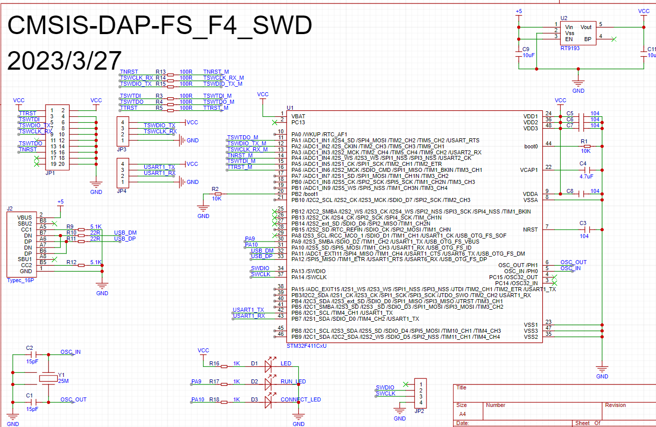
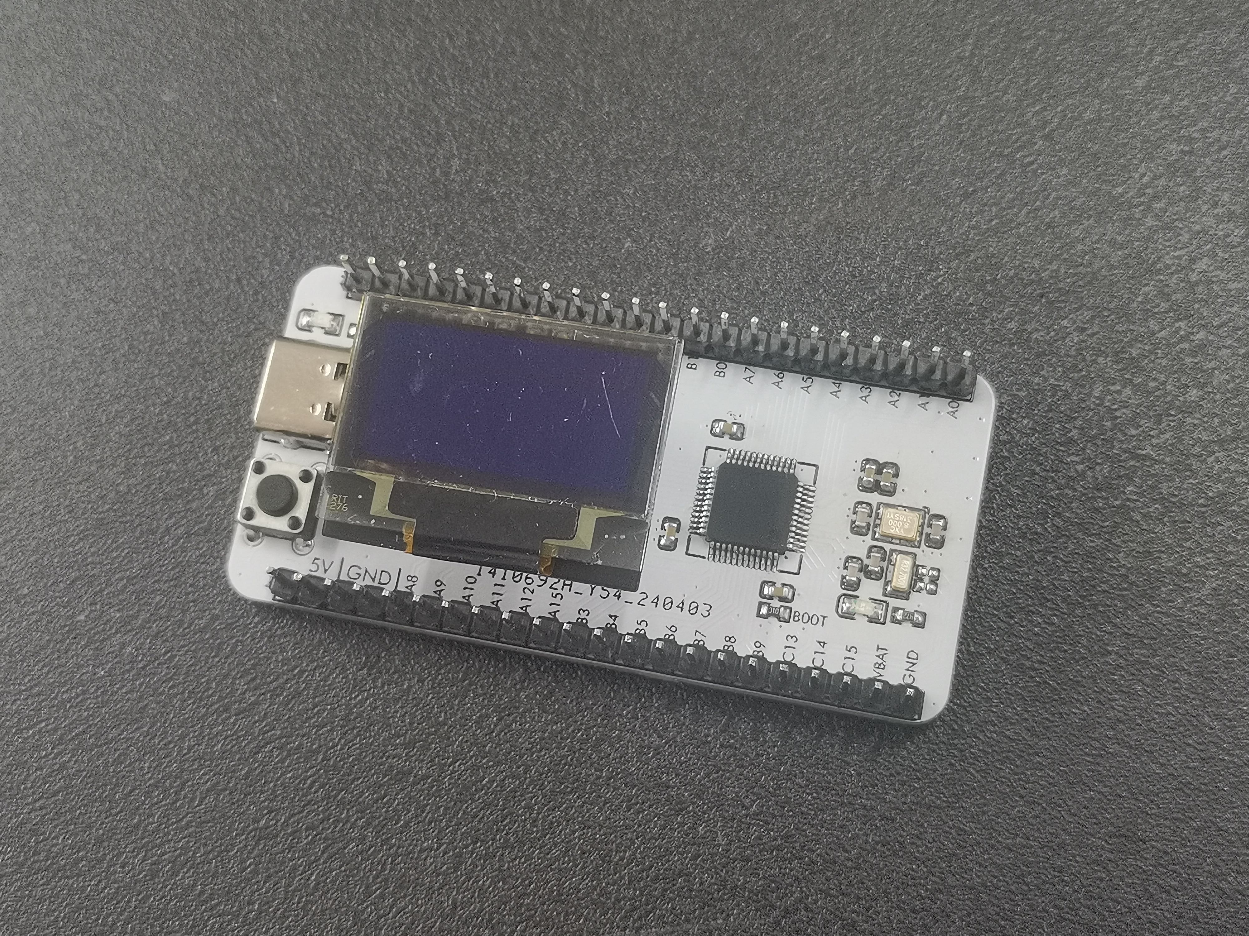
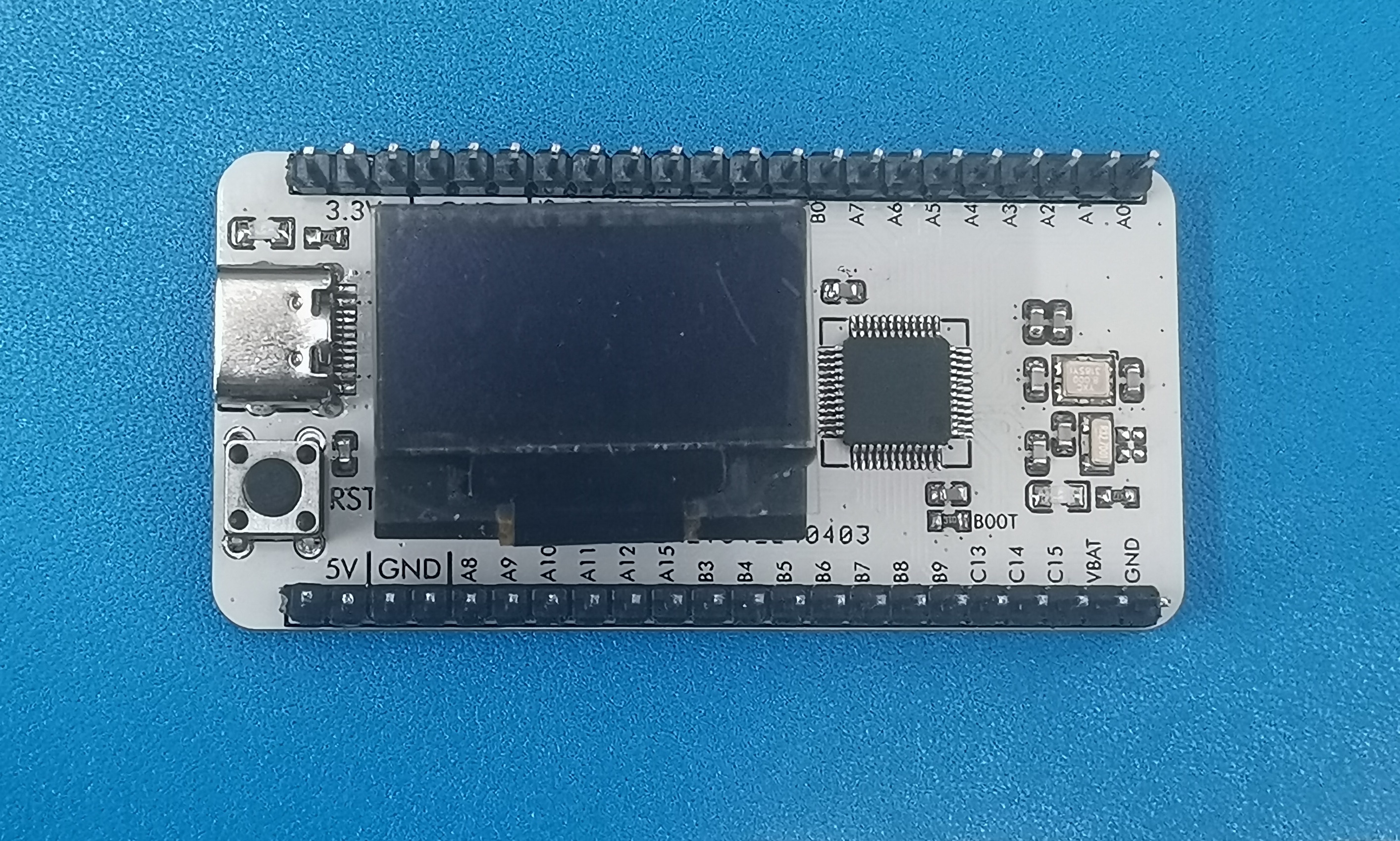
Based on STM32F411, the high-speed DAP-LINK has a download speed similar to, but slightly faster than, that of Zhengdian Atom's high-speed DAP-LINK.
This module uses the STM32F411 as the main control chip, employs the open-source DAP protocol, and utilizes high-speed USB for high-speed downloading. It follows the layout of Zhengdian Atomic's high-speed DAP-LINK and currently only supports SWD functionality, with a virtual USB serial port.
This project includes a casing and has been 3D prototyped for verification.
Schematic diagram .
DAP_LINK_V1.0.hex
PDF_DAP_LINK_V1.0.1.zip
Altium_DAP_LINK_V1.0.1.zip
PADS_DAP_LINK_V1.0.1.zip
BOM_DAP_LINK_V1.0.1.xlsx
95315
[Microcontroller] Simple Oscilloscope Project Based on GD32 Microcontroller
Oscilloscope
Project Description:
This project is a simple digital oscilloscope based on the GD32F103C8T6 microcontroller, designed to measure and display waveform signals. An external signal input is used to feed the waveform signal into the microcontroller for sampling and processing, and the waveform is displayed in real-time on an LCD screen.
Main Functions: 1. Waveform Signal Acquisition: The waveform signal is input to the analog input pin of the microcontroller via an external circuit, and sampled using the microcontroller's analog-to-digital converter (ADC). 2. Waveform Processing: The acquired analog waveform signal is digitized, including data processing and filtering. 3. Waveform Display: The acquired waveform is displayed in real-time on the LCD screen for user observation and analysis.
Hardware Components: 1. GD32F103C8T6 Microcontroller: As the core control unit of the project, responsible for acquiring, processing, and displaying waveform signals. 2. LCD Screen: Used to display waveform images and provide a user interface. 3. External Signal Source: Provides the waveform signal to be measured; this can be any circuit or device that generates waveform signals.
Software Design: 1. Waveform Signal Acquisition and Processing Program: Utilizes the microcontroller's ADC module for digital sampling and processing of analog signals, achieving waveform data acquisition and processing. 2. Waveform Display Program: Through an LCD driver, displays the processed waveform data on the LCD screen, forming a waveform image. 3. User Interface Program: Designs a simple and intuitive user interface, including waveform display, trigger settings, and measurement parameter display functions, providing a user-friendly operating experience.
Project Features: 1. Ease of Use: Employs a simple hardware and software design, making the oscilloscope easy to operate and learn, suitable for beginners and enthusiasts. 2. Openness: The project has a certain degree of scalability and customizability; users can expand and optimize functions according to their needs. 3. Educational Value: As a simplified implementation of a digital oscilloscope, it can serve as a teaching experimental platform, helping students understand the working principle of oscilloscopes and the basic methods of digital signal processing.
Through the above design, a simple digital oscilloscope based on the GD32F103C8T6 can be implemented for measuring and displaying waveform signals, possessing certain practical and educational value.
VID_20240408_164118.mp4
PDF_【Microcontroller】A Simple Oscilloscope Project Based on the GD32 Microcontroller.zip
Altium_【Microcontroller】Simple Oscilloscope Project Based on GD32 Microcontroller.zip
PADS_【Microcontroller】A Simple Oscilloscope Project Based on GD32 Microcontroller.zip
95318
Screen Adapter Board - Compatible with Taishanpai
The project includes several screen adapter boards that are compatible with the Taishanpai Rk3566 development board.
This project introduces
a collection of screen adapter boards compatible with the Taishanpai Rk3566 development board, and will be updated periodically. When using them, pay attention to the maximum backlight current and interface orientation!
Open source documentation: Currently, the documentation for each screen is attached to the project file; it will be compiled and uploaded to Gitee later.
The H0400S001
is a 4-inch, 400x960 resolution rectangular screen using a MIPI interface.
PCB Project Name: H0400S001
Documentation Folder Name: H0400S001
Features:
Content
Parameters
Dimensions :
4-inch
module Dimensions:
42.9(H) × 102.08(V) × 1.58(T) mm
Interface:
MIPI or RGB + 3 SPI
Maximum Backlight Current:
20 mA
Attachment Files Description

H0400S001.zip
PDF_Screen Adapter Board - Compatible with Taishanpai.zip
Altium Screen Adapter Board - Compatible with Taishanpai (zip file)
PADS Screen Adapter Board - Compatible with Taishanpai.zip
BOM_Screen Adapter Board-Compatible with Taishanpai.xlsx
95319
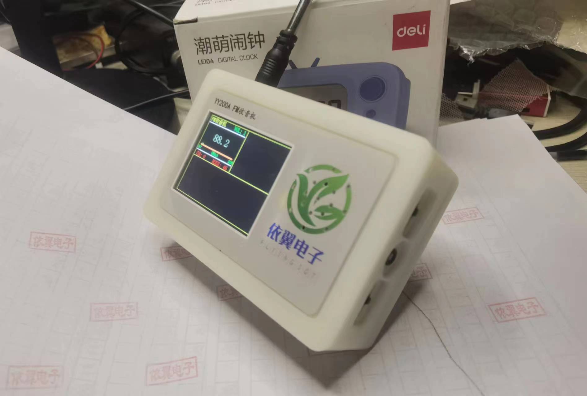
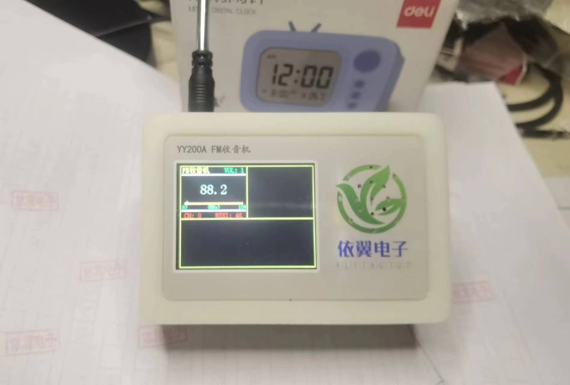
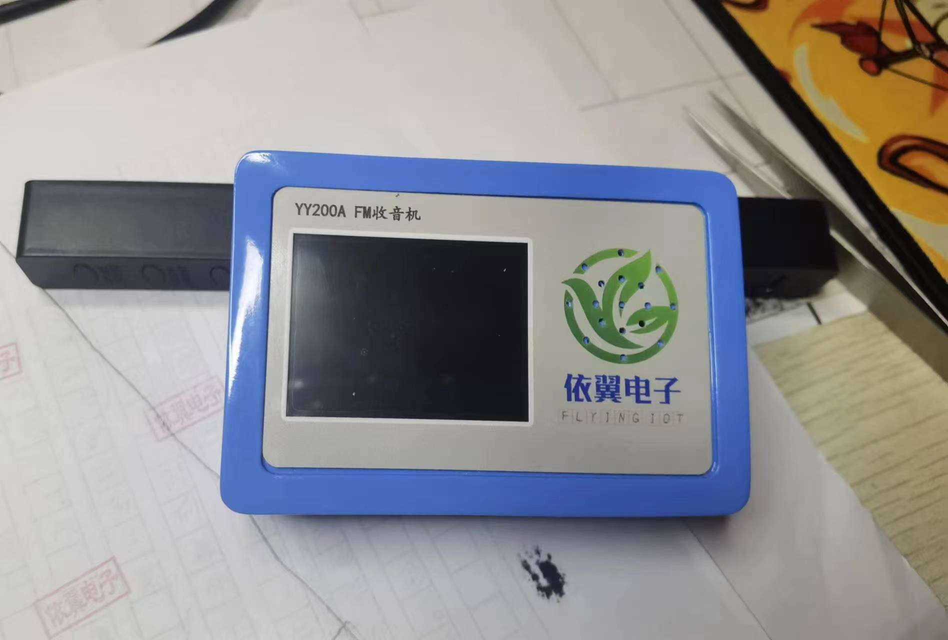
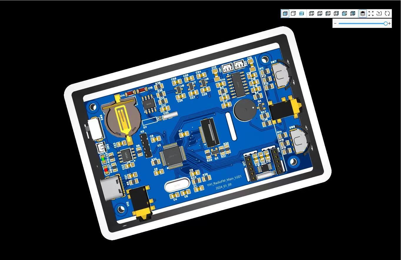
FM radio based on STM32F103 driving RDA5807
STM32F103C8T6 microcontroller, FM chip, RDA5807M
Update Log
2024.02.23
First time organizing and open-sourcing this project.
Hardware version V201,
Software version V2.0.0.20231225_Beta.
Microcontroller: STM32F103C8T6. FM chip: RDA5807M.
Product demonstration video:
Bilibili demonstration video (click to watch).
FM radio based on STM32F103C8T8, with volume adjustment, frequency switching, station switching, etc.
The circuit board has a reserved interface for a real-time clock, which will be updated later.
STM32 Radio V2 (V2.0.0.20231225_Beta).zip
PDF_FM Radio Based on STM32F103 Driving RDA5807.zip
Altium_FM Radio Based on STM32F103 and Driving RDA5807.zip
PADS_FM Radio Based on STM32F103 and RDA5807.zip
BOM_FM Radio Based on STM32F103 Driving RDA5807.xlsx
95320
electronic


 京公网安备 11010802033920号

 M5-192/192-10YI


