First of all, thank you to LCSC for hosting this summer fun event (I can get free coupons again, haha!).
In the wave of modern outdoor adventure, an advanced smart outdoor compass is undoubtedly an indispensable assistant for explorers. This smart compass combines cutting-edge technology with user-friendly design, providing explorers with accurate and convenient directional guidance, making every outdoor trip safer and more efficient.
This smart outdoor compass uses a high-precision gyroscope and magnetic sensor, which can sense changes in the Earth's magnetic field in real time, providing accurate directional indications even in complex geographical environments. It helps explorers quickly plan routes and avoid getting lost.
The smart compass has a simple and elegant design, made of lightweight materials, making it easy to carry and easily attached to a backpack or belt. Its display uses high-definition touch technology, which is clearly visible even in strong light. The interface layout is intuitive and user-friendly, allowing explorers to easily operate various functions.
In addition to basic directional guidance, this smart compass also has a variety of practical features.
In terms of battery life, this smart outdoor compass performs excellently. It uses a high-capacity lithium battery, supporting long standby and continuous use.
1. Hardware Design
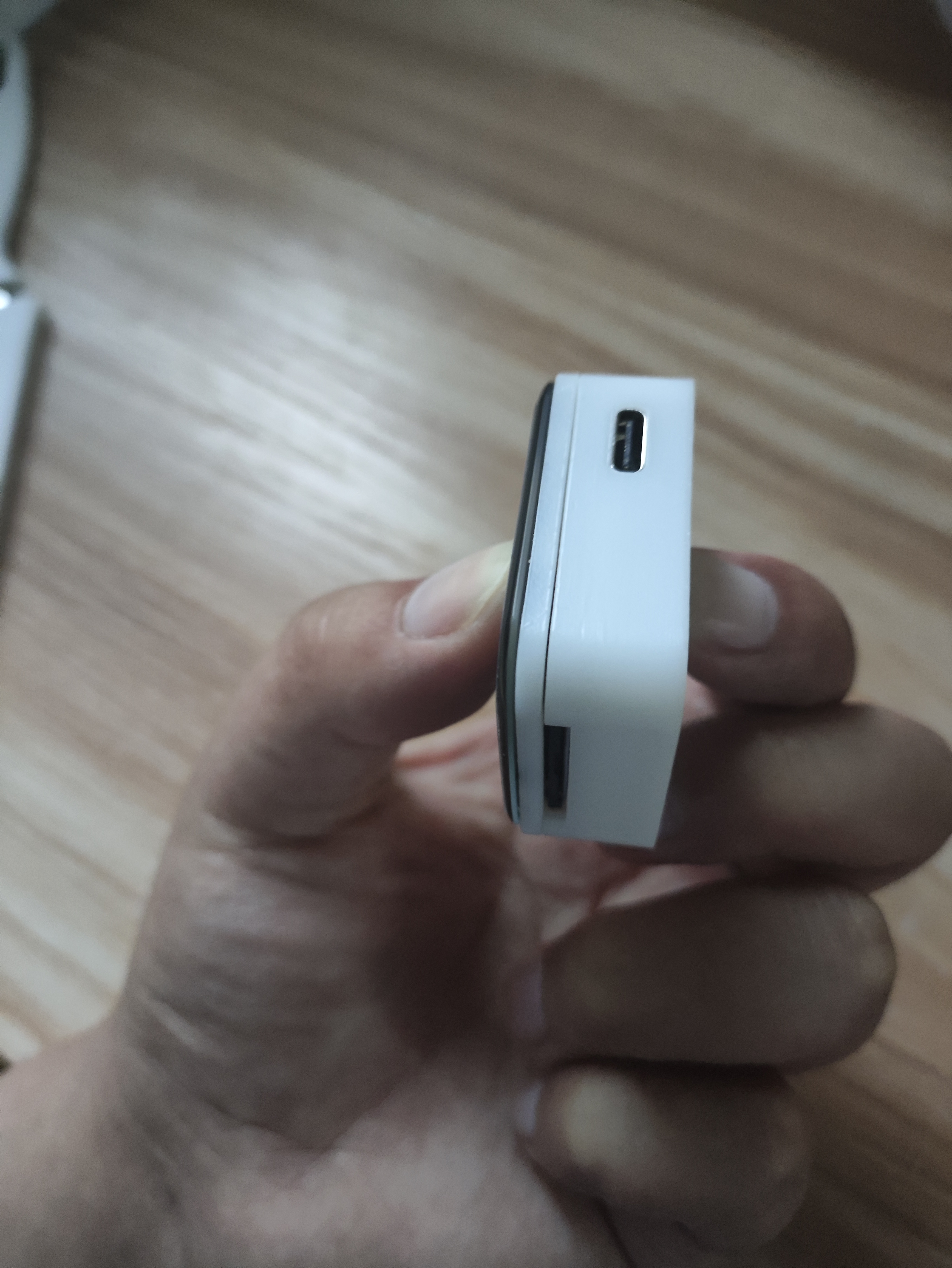
: The main controller uses an ESP32S3R8, the sensor is a QMC5883L, and the screen is a 1.69-inch touchscreen from Puyang. A TP4056 is used to charge the lithium battery; since the battery has its own protection board, no additional protection circuitry is used.
It supports automatic power supply and USB switching, and uses an LDO to 3.3V converter. Currently, the LDO is getting quite hot; I'll try replacing it with a dedicated power management chip when I have time. A 0.5mm 30-pin connector is used to bring out the GPIO for easy expansion of future functions.
The programming process uses the ESP32S3's USB port without additional soldered headers, limiting the layout. The board is relatively simple, the design is so-so, but it works, haha.
2. Soldering:
The most difficult part of the soldering process is the ESP32S3; everything else is fine. I used a hot air gun. You can preheat the board first, then apply solder paste (a little extra is fine), then blow the solder out; it will come out on its own. Finally, apply some flux and use a soldering iron to smooth it out.
Just be careful about the temperature of that screen holder, otherwise it will easily melt.

3.
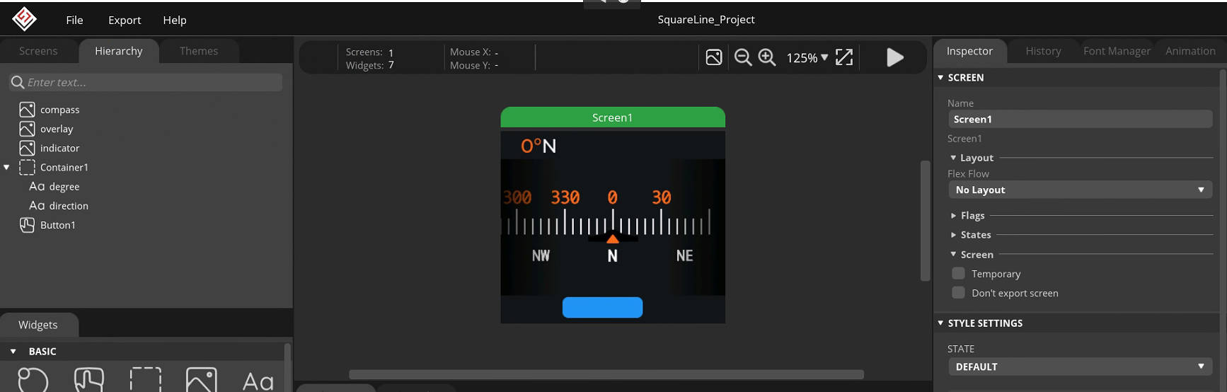
All the software development code is on GitHub. It is developed using IDF. The screen driver is ST7789V+CST816S, which is very common. The page is LVGL. The UI is based on a YouTuber's work (I have no aesthetic sense, haha).
wx-dev/esp32s3-idf-watch (github.com)
The geomagnetic sensor uses QMC5883L
to read the sensor
void qmc5883l_read_xyz(t_sQMC5883L *p) { uint8_t status, data_ready = 0; int16_t mag_reg[3];
qmc5883L_register_read(QMC5883L_STATUS, &status, 1); // Read the status register
if (status & 0x01) { data_ready = 1; } if (data_ready == 1) { data_ready = 0; qmc5883L_register_read(QMC5883L_XOUT_L, (uint8_t *) mag_reg, 6);
p->mag_x = mag_reg[0]; p->mag_y = mag_reg[1]; p->mag_z = mag_reg[2]; }}
calibrate geomagnetic sensor
void calibrateMag(){ int x,y,z; // triaxial data int xMax, xMin, yMax, yMin, zMax, zMin; // initialization t_sQMC5883L p; qmc5883l_read_xyz(&p); xMax=xMin=x=p.mag_x; yMax=yMin=y=p.mag_y; zMax=zMin=z=p.mag_z; offsetX = offsetY = offsetZ = 0; for(int i=0;i { qmc5883l_read_xyz(&p); x=p.mag_x; y=p.mag_y; z=p.mag_z; // Calculate maximum and minimum values // Calculate the maximum and minimum magnetic field strength of the sensor when it rotates around the X, Y, and Z axes if (x > xMax) xMax = x; if (x xMin = x; if(y > yMax ) yMax = y; if(y yMin = y; if(z > zMax ) zMax = z; if(z zMin = z; vTaskDelay(100 / portTICK_PERIOD_MS); } // Calculate correction amount if (abs(xMax - xMin) > CalThreshold) offsetX = (xMax + xMin) / 2; if (abs(yMax - yMin) > CalThreshold) offsetY = (yMax + yMin) / 2; if (abs(zMax - zMin) > CalThreshold) offsetZ = (zMax + zMin) / 2; ESP_LOGI(TAG, "offsetX = %d offsetY = %d offsetZ = %d ", offsetX, offsetY, offsetZ); vTaskDelay(5000 / portTICK_PERIOD_MS);}
Calculate the angle value.
void qmc5883l_fetch_azimuth(t_sQMC5883L *p) { qmc5883l_read_xyz(p); float headingRadians = atan2((double)((p->mag_y)-offsetY),(double)((p->mag_x)-offsetX)); // Ensure data is between 0 and 2 * PI if (headingRadians headingRadians += 2 * M_PI; } int headingDegrees = headingRadians * 180 / M_PI; headingDegrees += -5; // Magnetic declination // Ensure data is between 0 and 360 if (headingDegrees > 360) { headingDegrees -= 360; } p->azimuth = (float) Currently, calibration has been added ,
but the accuracy still seems unsatisfactory, especially after switching from the xY axis to the xZ axis. I'm unsure if this is a sensor or code issue.
Page Design
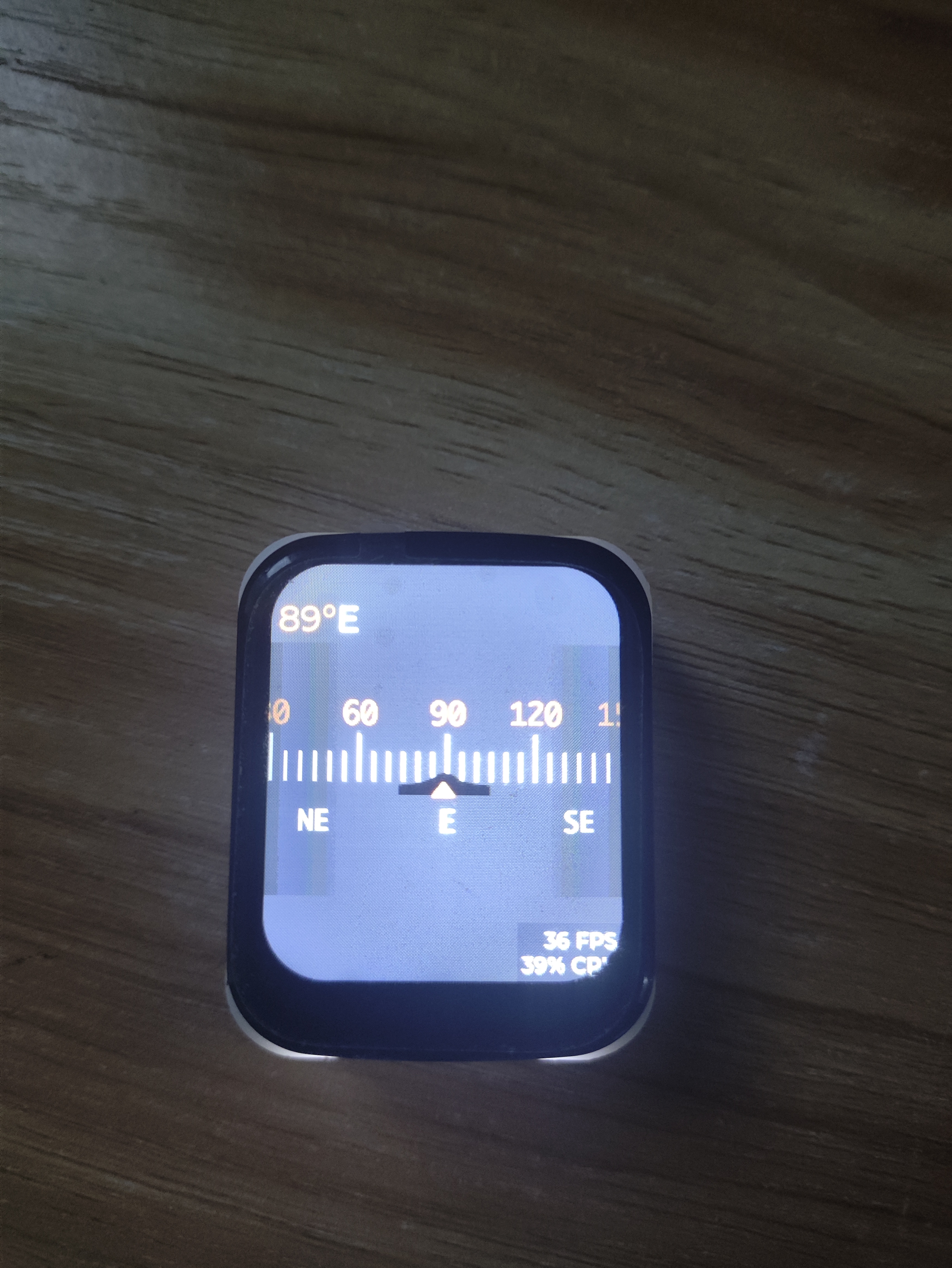
4. Testing:
Currently, the geomagnetic data is being read normally without major problems; the only issue is the slightly poor accuracy. Further optimization is needed. Regarding hardware, the lack of a dedicated power management chip causes the board to get a bit hot.
Later, with the addition of an attitude sensor and temperature/humidity sensor, it will become a more advanced device and can even be used as a development board! Haha.
5. Finished Product Showcase


 京公网安备 11010802033920号

 SMS1546-001


