Based on the "Bootdrive" program (Baldwisdom/BootDrive at master · osbock/Baldwisdom · GitHub), this program is read from the chip and burned onto another Arduino UNO development board via serial port using the stk500 protocol.
Pins used:
Pins 0 and 1 (serial port),
Pin 4 (output reset signal)
, Pin 7 (connected to a switch to determine if the program copying mode has been entered).
Reset pin
usage:
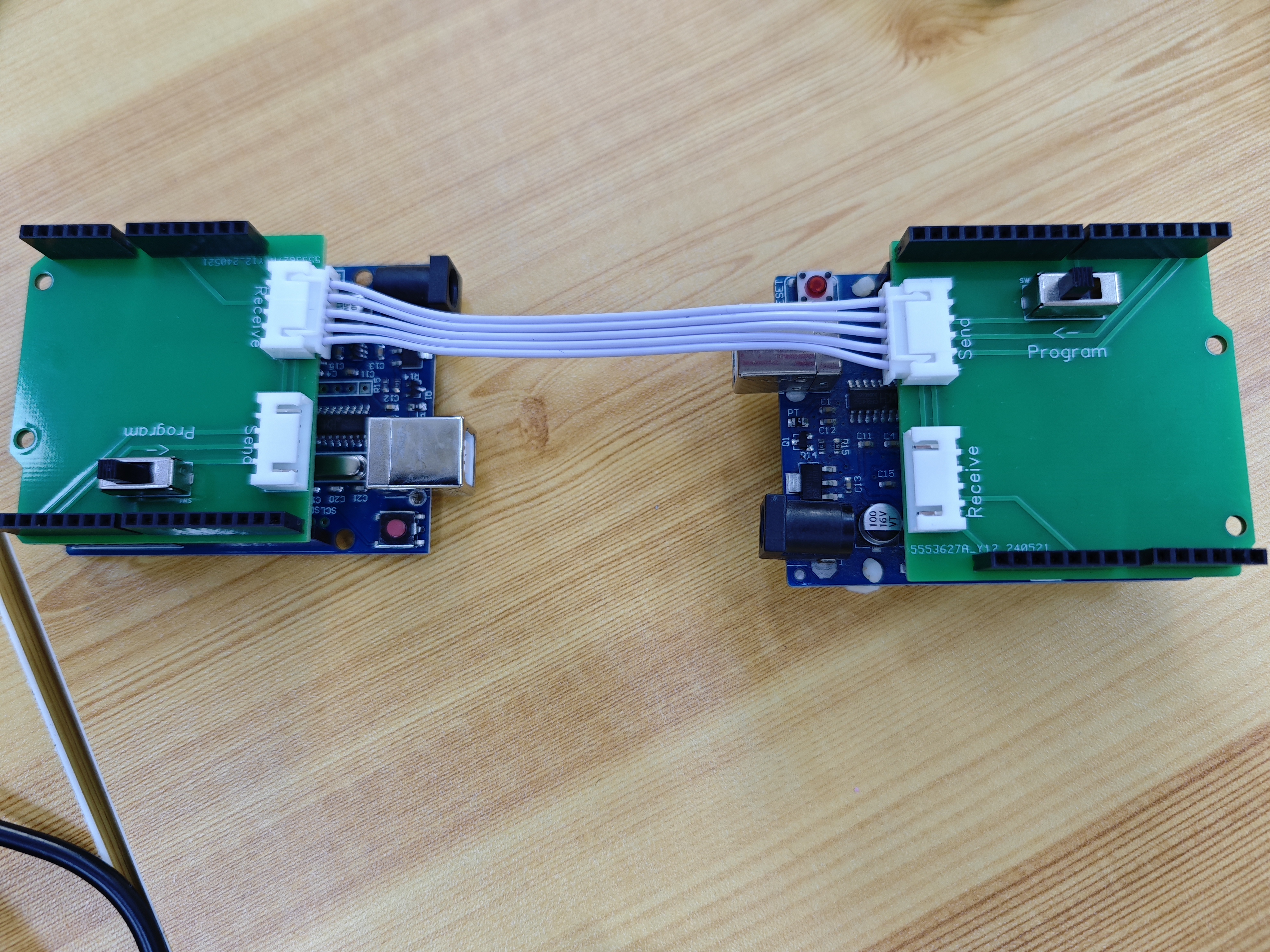
Connect the expansion boards to both Arduino UNO boards, then download the program copying signal to one of them (using it as a programmer). Connect the two boards with an XH2.54 5P cable with the same interface direction (connecting the programmer's send interface to the target board's receive interface). Turn on the programming switch on the programmer board as indicated by the arrow, and turn off the switch on the target board. Upon power-up, the program can be copied to the target board. The development board on the right in the diagram is used as the programmer, and the target board is on the left.
Arduino_copier.zip
PDF_Arduino UNO Program Copy Expansion Board.zip
Altium_Arduino UNO Program Copy Expansion Board.zip
PADS_Arduino UNO Program Copy Expansion Board.zip
BOM_Arduino UNO Program Copy Expansion Board.xlsx
94546
Cat Electric Mosquito Repellent Heater
The electric mosquito repellent liquid is heated by RTP resistance heating, and the outer shell is designed as a cat box, displaying the cat's expression and heating status on a 2.0-inch LCD screen.
Summer brings a multitude of mosquitoes, making electric mosquito repellents indispensable. This design uses RTP resistors to heat the liquid mosquito repellent, and the casing is shaped like a cat's box. A 2.0-inch LCD screen displays the cat's expression and heating status.
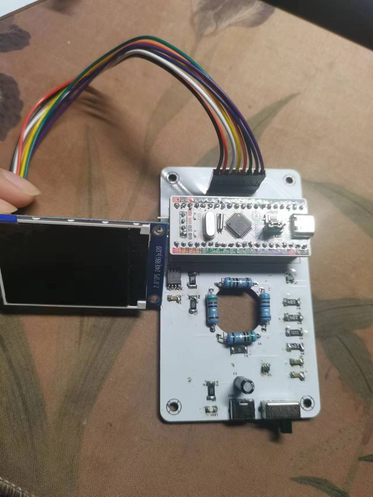
The heating circuit references an open-source electric mosquito repellent project, using an LM321 to control the heating and stopping of four 5.1R 2W metal film resistors. The display uses a GDE230C8T6 minimum system board and a 2.0-inch color LCD screen.
PCB soldering:
Larger component packages were chosen for ease of soldering, making it easier for beginners.
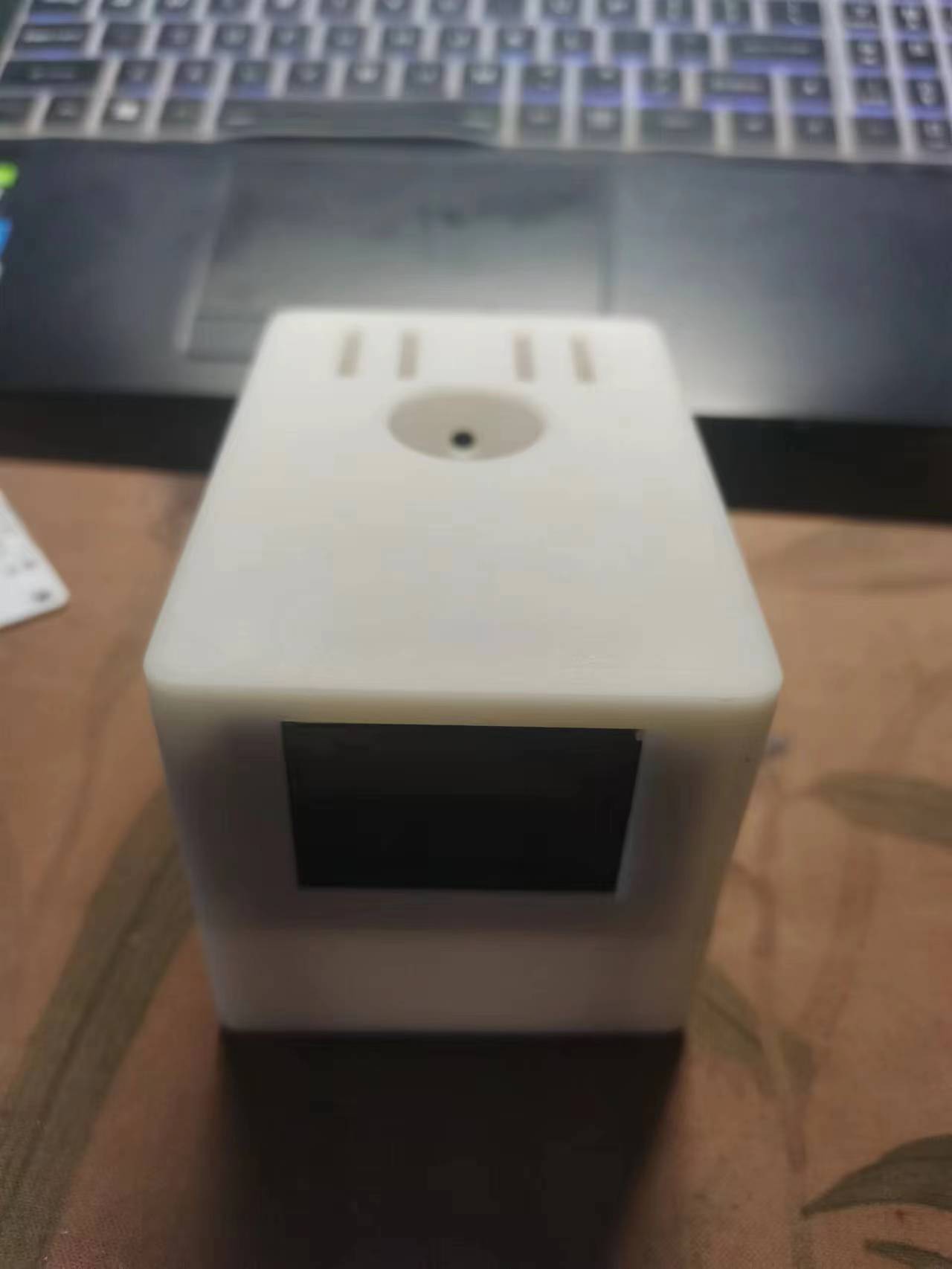
3D casing:
Care must be taken to consider the screen size and the placement of the mosquito repellent liquid.
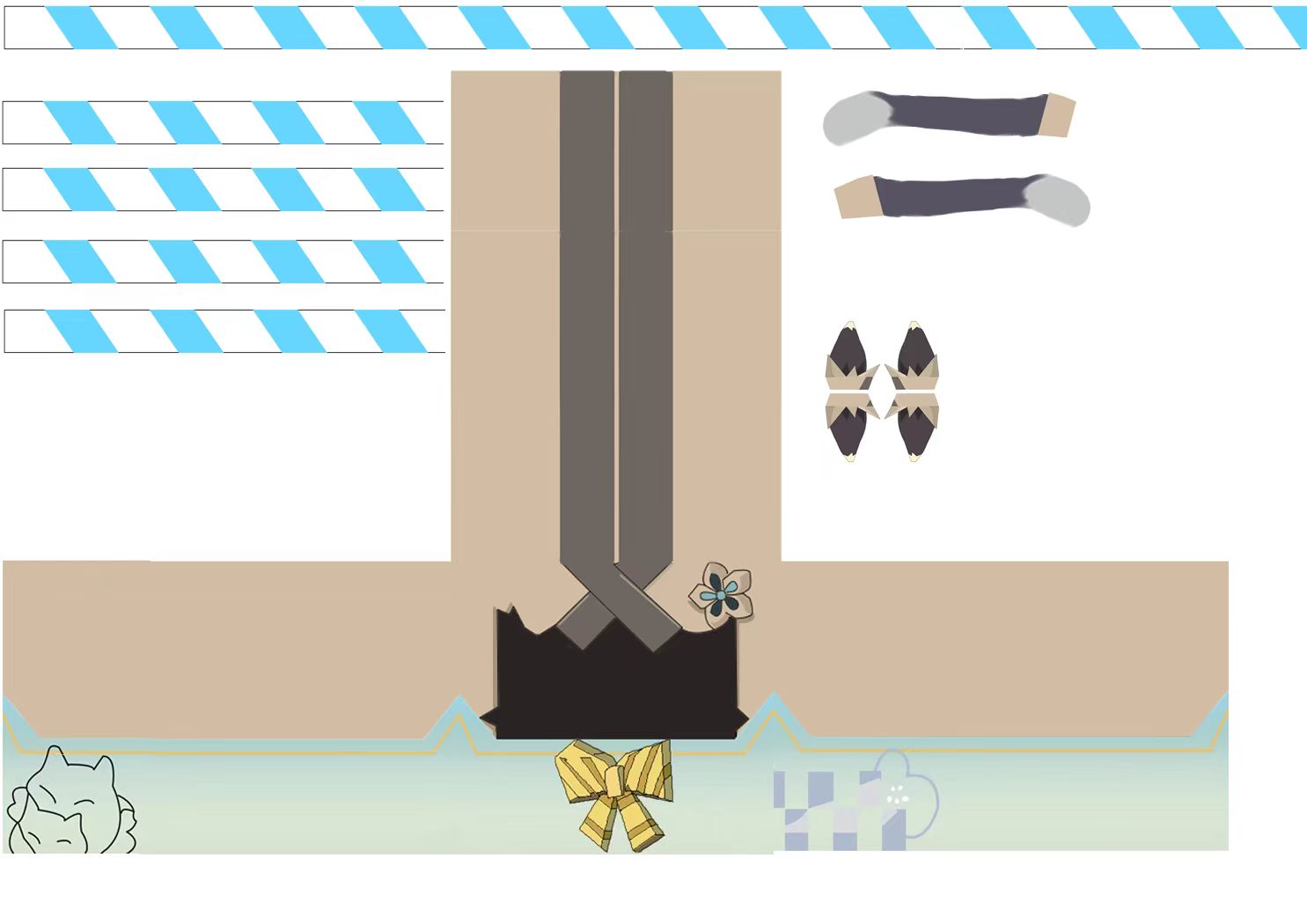
Decoration:
To enhance the heater's appearance, some decorations were added, inspired by Kira's cat box from Genshin Impact.
Code:
The heating status and screen display require programming; refer to the module porting manual for the GD32E230C8T6 development board. The connection is as follows: https://lceda001.feishu.cn/wiki/JFDCw6gYHiycvakpHj5cSSy0nj9
. Power-on verification is required.


PDF_Cat Electric Mosquito Repellent Heater.zip
Altium_Cat Electric Mosquito Repellent Heater.zip
PADS_Cat Electric Mosquito Repellent Heater.zip
BOM_Cat Electric Mosquito Repellent Heater.xlsx
94548
8-segment LED port test indicator light sequential light
An 8-segment LED test indicator light
with a common cathode or common anode configuration, using 8 pins to control the lighting status of 8 LEDs.
Project Background:
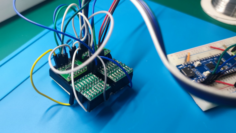
I was just starting out learning PCB design with JLCPCB, and I often tested my ideas on breadboards.
When testing a 74HC595D series circuit, I wanted to use 3 GPIOs to control the lighting status of 16 LEDs
. For this, I specifically soldered some small boards to the breadboard for testing
and improvement.
First, I bought some surface mount to through-hole (SMT) boards online

and soldered resistors and LEDs onto them, like this.

Next, I connected the resistors and LEDs, using jumper caps.
To achieve common cathode or common anode, I needed a wire to connect a whole row of pins.
I used a header pin, soldered all the pins, and led out a wire.
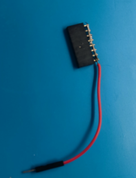
The finished product was
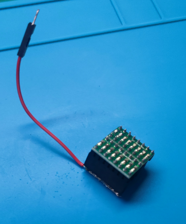
an 8-LED common anode LED sequential light.
Project Testing Real-World
Improvement:
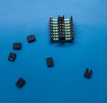
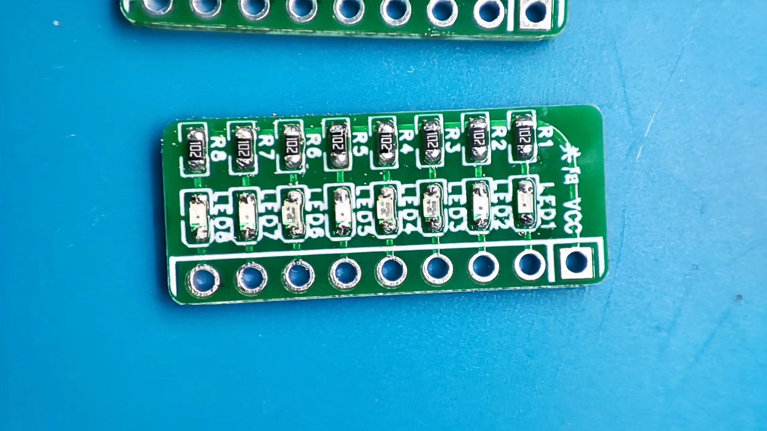
To change this ugly interface, save space, and make it cleaner, I decided to design a small board to change the situation.
I wanted this small board to be able to be directly plugged into the breadboard, so I used a 1x9P board. The pin headers (2.54mm pitch)
may require either common cathode or common anode configurations in actual testing. Additionally, because small breadboards have limited holes, I wanted to be able to fit two such small boards
so the power supply could be connected externally via wires. The eight LEDs would be directly plugged into the breadboard.
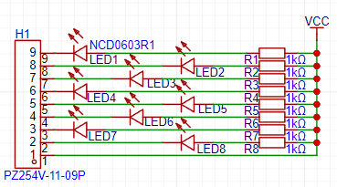
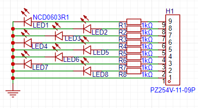
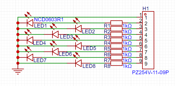
Therefore, I decided to use four different designs: common cathode, common anode, common terminal at the top, and common terminal at the bottom.
Common anode LEDs light up at low levels, and common cathode LEDs light up at high levels.
They look like this: [Image of common anode_top common terminal], [Image of
common anode_bottom common terminal], [Image of common cathode_bottom common

terminal], [Image of common cathode_top common terminal] . The soldering test board arrived. I prepared the components and started soldering. All the boards are now ready. Here's a comparison photo with the previous ones. Other notes: Board soldering is relatively simple. You can get it for free from JLCPCB. The LED color and resistance can be changed to your liking or what's suitable. For those who don't want to do it themselves, you can search for "8-segment LED port test light" on Taobao. Finally, I wish everyone a smooth board-making process.


972e8749bc6aee15f58be43b88e06fd6.mp4
PDF_8-segment LED port test light indicator light sequential light.zip
Altium_8-segment LED port test light indicator light sequential light.zip
PADS_8-segment LED port test light indicator light sequential light.zip
BOM_8-segment LED port test light indicator light sequential light.xlsx
94549
GD32E230 Minimum System (LCSC Team)
The GD32F230 minimum system verification is genuine. The original version, produced by the LCSC team, is a color version. Due to my limited capabilities, the verification version is in monochrome. The verification result is shown in the image—perfect!
This verification version replaced the 16-pin Type-C port with a micro connector based on the difficulty of soldering, changed the reset button from a two-pin to a four-pin one, and repositioned several other ribbon cables. Everything else follows the original routing from the LCSC team. Through several verifications of open-source files from teams and individuals, we found that the team's approach is generally more classic, and with minor adjustments, it can maintain board accuracy and has a higher fault tolerance. Some individual designs (including my previous ones, which are currently being checked and re-released one by one) have particularly poor logic, especially in terms of routing.
PDF_GD32E230 Minimal System (LCSC Team).zip
Altium_GD32E230 Minimal System (LCSC Team).zip
PADS_GD32E230 Minimal System (LCSC Team).zip
BOM_GD32E230 Minimum System (LCSC Team).xlsx
94552
The 51 Minimum System with School Emblem
A minimal 51 system with a school emblem has been added, along with some commonly used functions.
A CH340C microcontroller was used to implement a USB-to-serial converter, eliminating the need for an external programmer and facilitating program debugging.
The 3V output used an XC6206P332MR linear regulator in a compact SOT-23 package.
The LED module used a 0805 package with a 1K current-limiting resistor.
The motor driver used an L9110S, which is inexpensive and has a large current drive capability, handling 800mA of continuous current per channel and up to 5A of peak current.
The buzzer driver used an S8050NPN transistor. Since the buzzer is an inductive component, the current cannot suddenly drop to zero when it stops working, so a 1N5819WS Zener diode was connected in parallel as a release path. An
89C52 microcontroller was used as the main controller, employing a 12MHz crystal oscillator. Without a crystal oscillator, there is no timing cycle, and without a timing cycle, the code cannot be executed; therefore, the crystal oscillator is crucial for the microcontroller. A high-level signal to the RST pin of the microcontroller will automatically reset the system. The P0 port does not have a built-in pull-up resistor; an external pull-up resistor is required.
PDF_51 Minimal System with School Badge.zip
Altium_51 Minimal System with School Badge.zip
PADS_51 Minimal System with School Emblem.zip
BOM_51 Minimal System with School Emblem.xlsx
94554
Lattice-LCMXO2-256HC-FPGA Core Board
Lattice-LCMXO2-256HC-FPGA Core Board
Lattice's FPGA chip LCMXO2-256HC-4SG32C is
used to create a small core board that employs an active crystal oscillator, specifically a 22.579MHz crystal oscillator commonly used in audio circuits, which can be used in conjunction with an ADC/DAC.
![1111.png]

Test code lcomxo2.zip
20240527-123231.mp4
PDF_Lattice-LCMXO2-256HC-FPGA core board.zip
Altium_Lattice-LCMXO2-256HC-FPGA core board.zip
PADS_Lattice-LCMXO2-256HC-FPGA core board.zip
BOM_Lattice-LCMXO2-256HC-FPGA Core Board.xlsx
94555
electronic


 京公网安备 11010802033920号

 17225C


