Title: Following Mr. Wu's live-streamed board design for a small mobile phone based on the LCSC Taishanpai
board, I learned some high-speed signal design tips, which were quite useful.
Regarding software, the only Linux board I've worked with before was the I.MX6U, which was only good enough to turn on an LED. I tried using an old 6ULL virtual machine to install the Taishanpai compilation environment, but after several days of struggling to compile, I finally reinstalled it (I wish I hadn't been so lazy). By diligently following the videos and documentation, both Linux and Android compiled successfully. For
, since the 3.1-inch screen recommended by Mr. Wu hadn't arrived yet, I only soldered the board. In summary, don't use too much solder on the solder joints; just drag the soldering iron through once, but add plenty of flux!!! Before
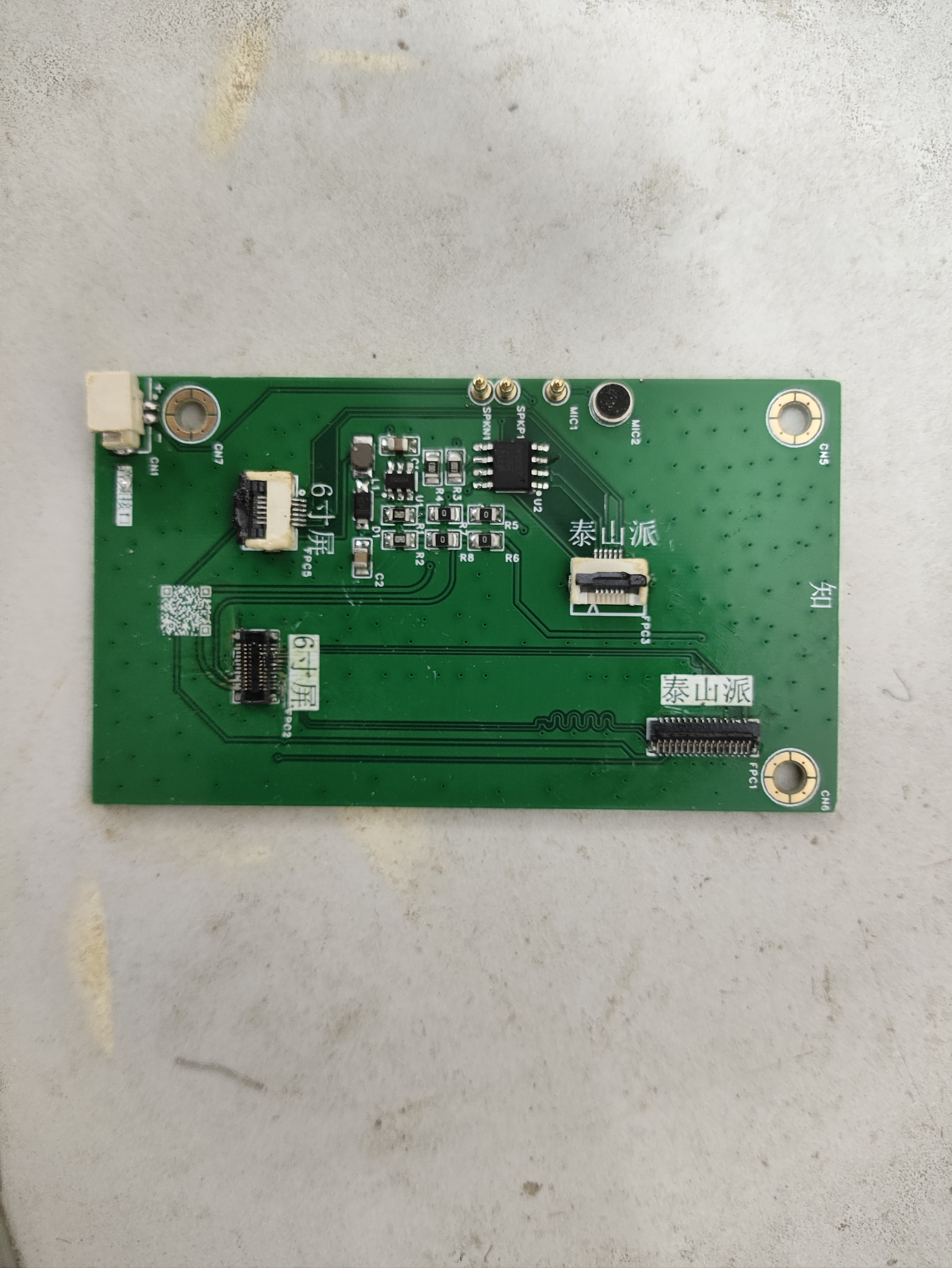
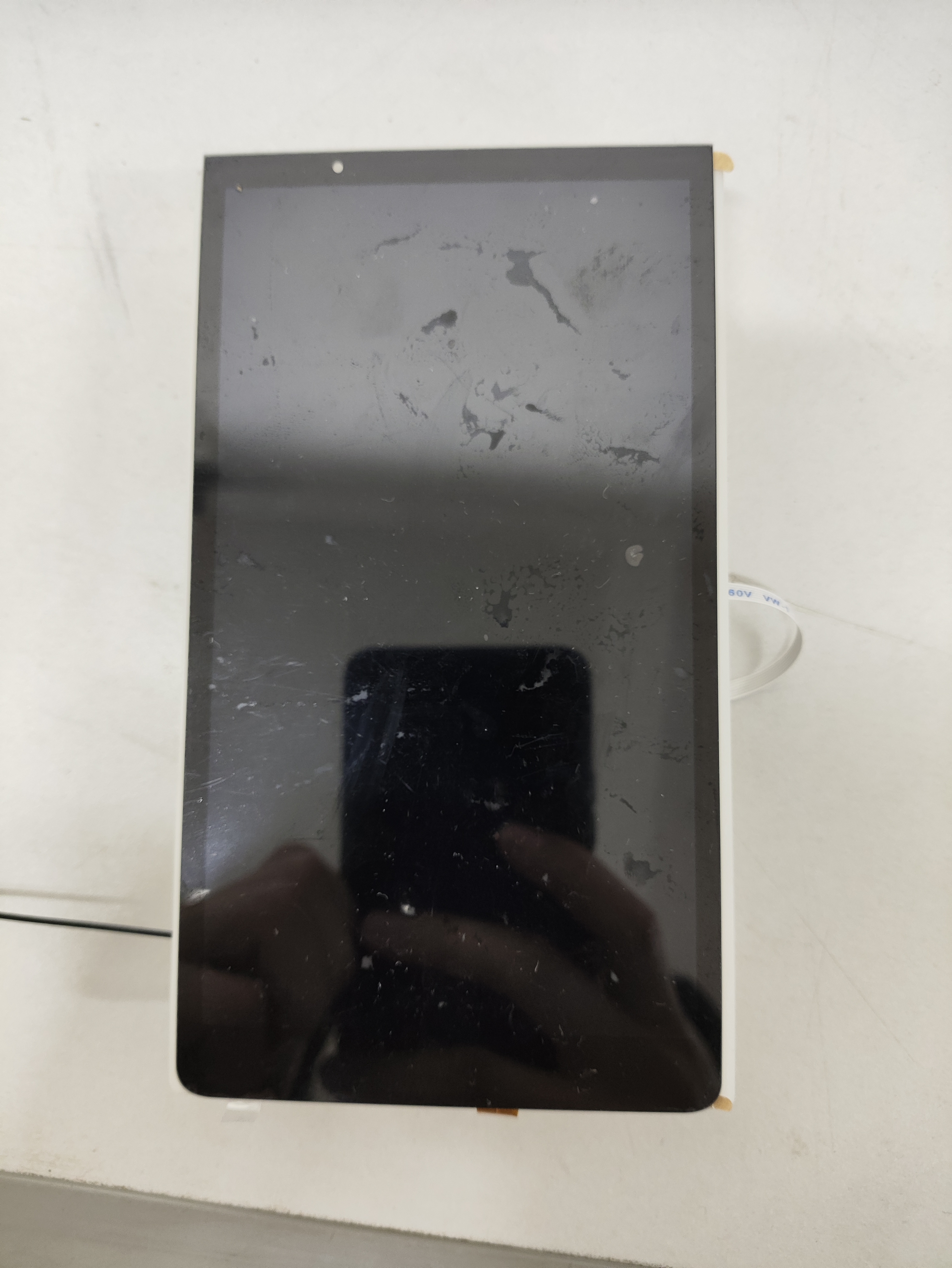
turning on the screen , I bought a 6-inch screen and adapter board for 39.9 yuan from a promotion on Maomao Screen
. I played around with it and roughly sketched the back of the 6-inch screen, measuring the holes for the touch and display cables with calipers. It's barely usable; it's attached.
This design cleverly combines high-performance hardware components with efficient software algorithms, aiming to provide enthusiasts and the education market with an economical yet fully functional self-balancing scooter solution. The entire project cost is kept below 300 RMB, achieving a perfect balance between cost-effectiveness and playability. The design uses the ESP32-WROOM as the main controller, integrating an MPU6050 gyroscope for attitude control, and is equipped with an OLED display for real-time status information, as well as four motor encoder interfaces to ensure precise motion control. For a detailed design reference, please refer to the reference project: https://oshwhub.com/yuyxz/coaxial-wheat-wheel-balance-car
I. Project Background and Objectives With the advancement of technology and the rise of DIY culture, personal mobile devices such as self-balancing scooters are becoming increasingly popular. However, most self-balancing scooters on the market are expensive and lack transparency, making it inconvenient for enthusiasts to learn and customize. This project aims to break this limitation by providing a low-cost, highly customizable self-balancing scooter solution through open-source design, encouraging technological exploration and innovative practices.
II. Hardware Selection and Design ### Main Controller: ESP32-WROOM The ESP32-WROOM is an ideal choice for this design due to its integrated WiFi and Bluetooth functions, powerful processing capabilities (dual-core 32-bit processor), and abundant GPIO resources. It efficiently processes sensor data, motor control, and wireless communication tasks, providing a robust control core for the self-balancing scooter.
### Sensors: MPU6050 Gyroscope The MPU6050 is a high-performance 6-axis motion processor that integrates a three-axis gyroscope and a three-axis accelerometer, a key component for achieving balance control. Connected to the ESP32 via an I2C interface, the MPU6050 accurately measures the vehicle's attitude changes, providing real-time data for the balance algorithm.
### Display: OLED Display To enhance user experience and facilitate debugging, an OLED display is incorporated into the design. Its compact size and lightweight design clearly display battery level, operating mode, speed, and other information, providing users with a clear overview of the vehicle's status.
### Motors and Encoders The self-balancing scooter uses a four-motor drive system, with each motor equipped with an encoder. Precise measurement of wheel speed enables precise dynamic control of the vehicle. The motor encoder interface is directly connected to the GPIO of the ESP32, and the motor output is adjusted through a precise PID algorithm to ensure balance, stability, and flexible motion control. Using a second-hand Nidec motor greatly reduces the cost of the motor. Note: When purchasing wheels (I used 6mm couplings, 80mm diameter Mecanum wheels), you need to ask the seller if the motor shaft can be installed.

III. Software Design and Implementation The software part mainly includes sensor data processing, motor control algorithm, user interface development, and wireless communication functions.
1. **Attitude Control Algorithm**: Based on the data from the MPU6050, an extended Kalman filter (EKF) is used to fuse accelerometer and gyroscope data to achieve accurate attitude estimation. On this basis, a PID control algorithm is applied to adjust the motor output according to the deviation to maintain vehicle balance.
2. **OLED Display Interface**: Using a UTFT library or a similar graphics library, a simple and intuitive user interface is designed. The displayed content includes, but is not limited to, vehicle status, mode switching options, and fault prompts, enhancing the user experience.
3. **Wireless Communication:** Utilizing the Wi-Fi functionality of the ESP32, a mobile app or web interface can be developed to enable remote monitoring, parameter adjustment, and firmware upgrades, providing users with greater customization options.
IV. Cost Control and Optimization: Through careful material selection and design optimization, the overall cost was strictly controlled to within 300 RMB. Key factors included: - Selecting cost-effective components, such as the multi-functional ESP32-WROOM, reducing the need for additional modules. - Utilizing open-source hardware and software resources to reduce R&D costs. - Streamlining the design, eliminating unnecessary functions, and maintaining a simple and efficient system.
V. Conclusion: This design successfully creates a low-cost, fully functional coaxial balance scooter by integrating the powerful performance of the ESP32, the precise sensing of the MPU6050, the intuitive display of the OLED, and the high-efficiency motor encoder system. This open-source design not only provides enthusiasts with a practical platform for learning electronics, control theory, and programming, but also provides educational institutions with a high-quality teaching tool, promoting the popularization and innovation of technical knowledge. In the future, we look forward to the community further improving and innovating based on this design, jointly promoting the development of personal mobile device technology.

code(1).zip
Bluetooth remote control app (based on appinventor).zip
Materials List.docx
Protective frame 1.STL
Installation Instructions.docx
Protective frame 2.STL
Body connecting bracket modified .STL
Body connecting frame link.STL
Body connecting frame link 2.STL
Print instructions.txt
Motor bracket modified .STL
PDF_A design based on a coaxial wheel self-balancing scooter.zip
Altium - A coaxial wheel-based self-balancing scooter. (zip file)
BOM_A coaxial wheel self-balancing scooter based on design.xlsx
94603
Smartphone Project Based on the Taishan School
A smart phone made with a 6-inch cat screen and Taishan style.
This document outlines
my participation in the LCSC Taishan Training Camp project. Based on the project's learning content, I transformed a development board into a small smartphone. Considering I had already purchased a 6-inch screen, I modified the schematic and 3D printed model of the original 3.1-inch screen to meet the requirements.
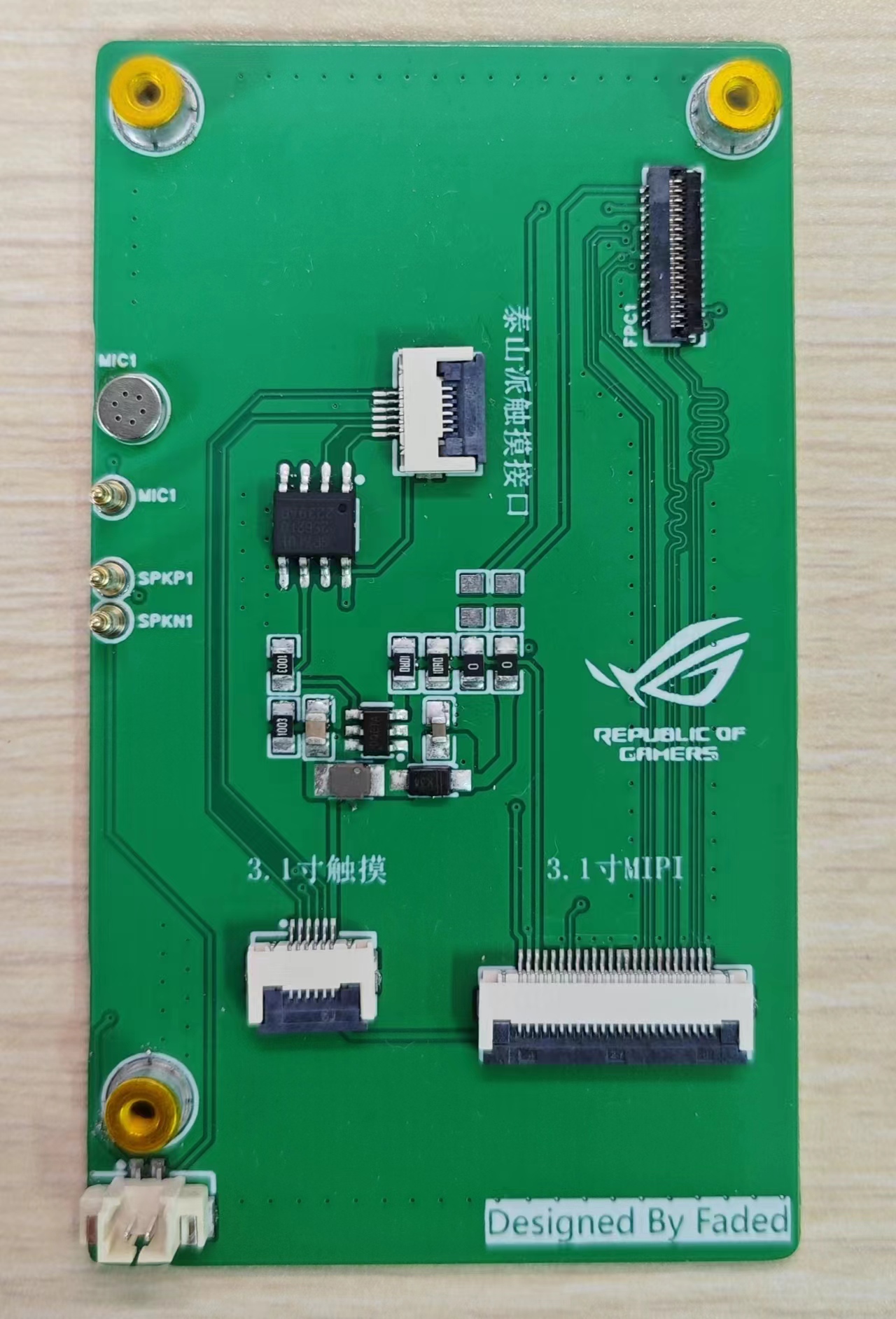
I. Schematic :
The connection relationship between the 6-inch and 3.1-inch screens is basically similar; only a few additional interfaces need to be added to accommodate the 6-inch screen. The schematic was modified to accommodate the screen's display. After modification, soldering was performed, as shown in the figure.
After soldering, the screen was connected to the development board.
II. Program:
Screen Display: Based on the learned content, the program needed to be rewritten according to the screen parameters. Download the attached file tspi-rk3566-dsi-v10.dtsi and manually replace the file kernel/arch/arm64/boot/dts/rockchip/tspi-rk3566-dsi-v10.dtsi to make the screen display correspond to the 6-inch screen.
For touchscreen, download and extract the gt9xx.zip attachment, manually replace the contents of the kernel/drivers/input/touchscreen/gt9xx folder, and
after completing the above steps, recompile the kernel and flash boot.img separately.
IMG_20240518_190007.jpg
IMG_20240518_190021.jpg
text.mp4
test.stl
Top Shell.STL
tspi-rk3566-dsi-v10.dtsi
gt9xx.zip
PDF_Smartphone Project Based on the Taishan School.zip
Altium_Smartphone Project Based on Taishanpai.zip
PADS_Smartphone Project Based on Taishan School.zip
BOM_Based on the Taishan School Smart Phone Project.xlsx
94604
electronic
 turning on the screen , I bought a 6-inch screen and adapter board for 39.9 yuan from a promotion on Maomao Screen
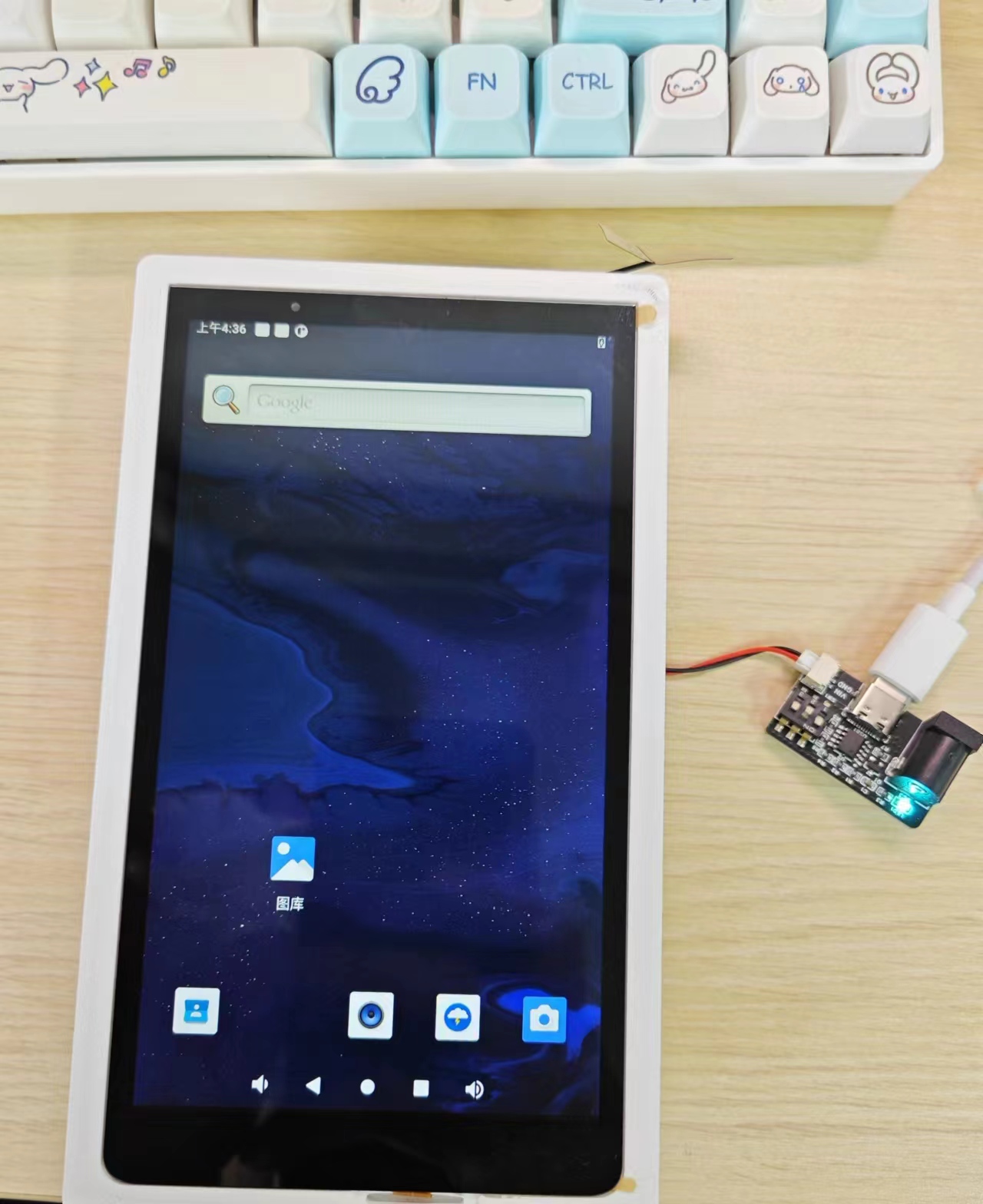


 京公网安备 11010802033920号

 M55342K04B154DRT1V


