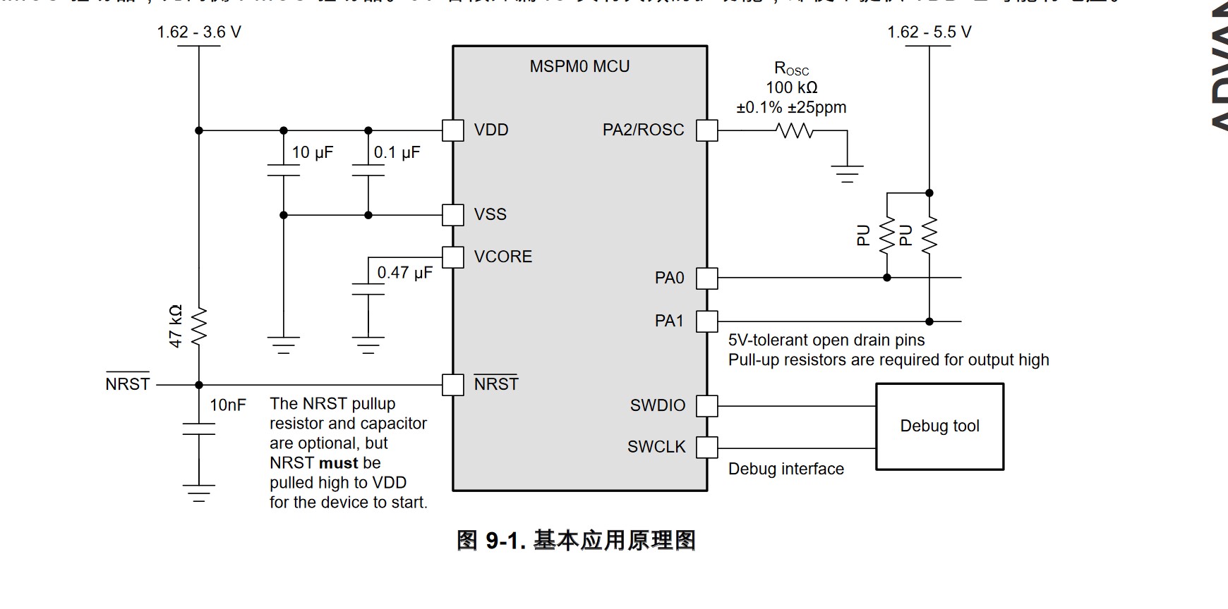
Working principle,
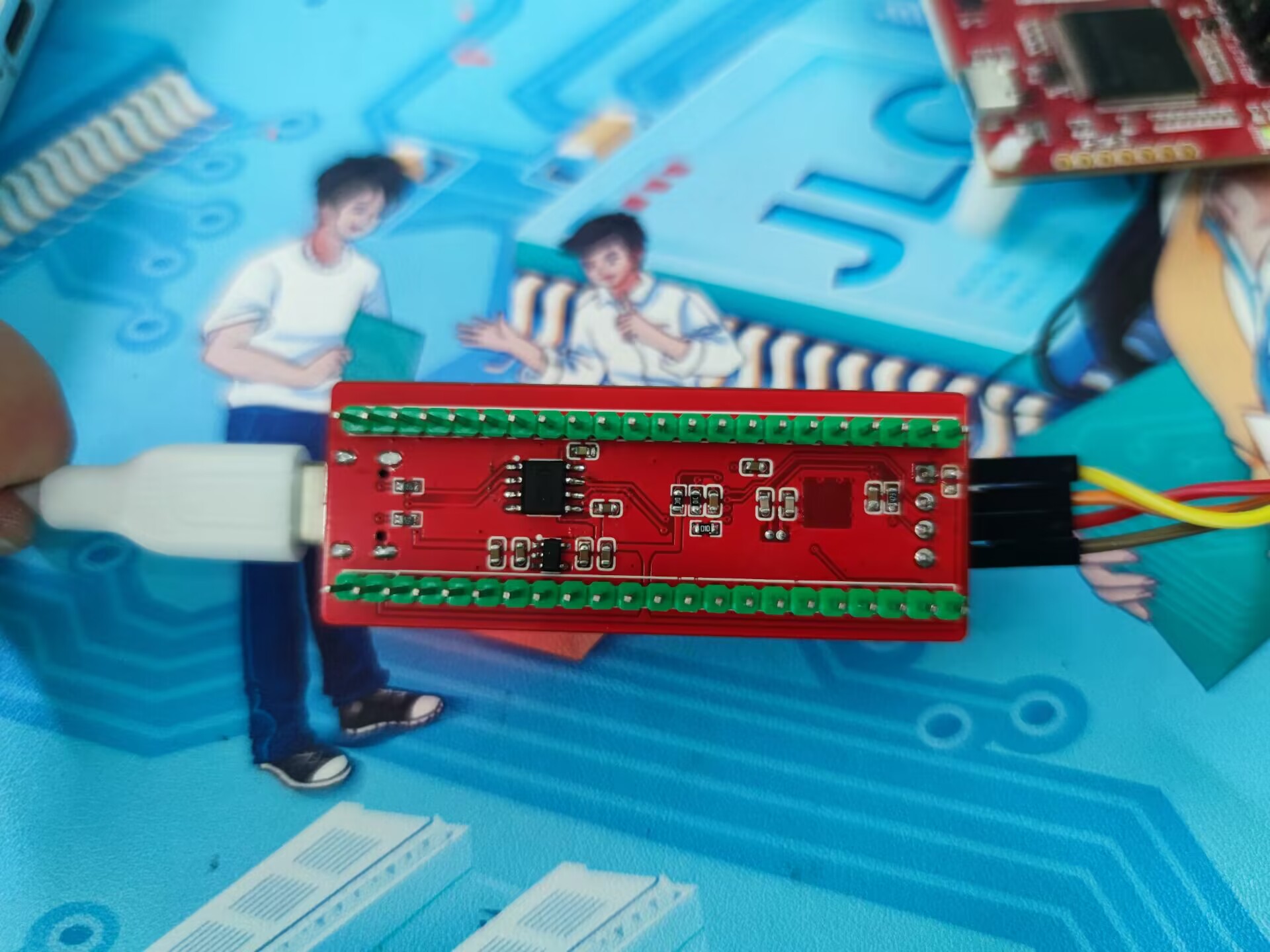
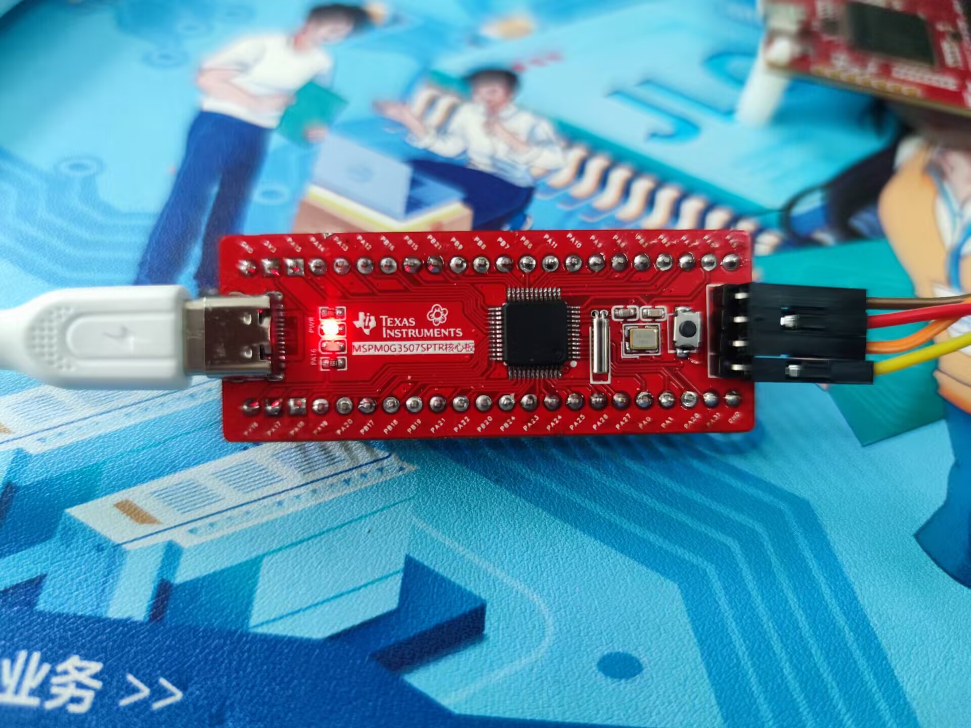
appearance
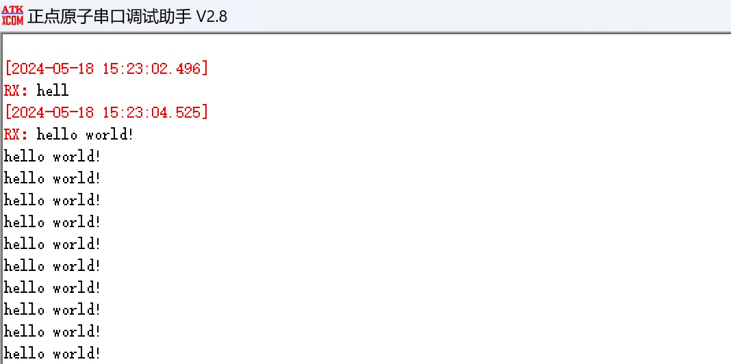
verification,
serial port 0,
LED light
PDF_MSPM0G3507SPTR core board.zip
Altium_MSPM0G3507SPTR core board.zip
PADS_MSPM0G3507SPTR core board.zip
BOM_MSPM0G3507SPTR Core Board.xlsx
94702
Improved 4S battery interface solution
Modifying the 4S model aircraft lithium battery using the ICX301 interface and 2.54mm pin header and nut allows the elimination of the balance head.
1. Use 15mm 2.54mm long pin headers.
2. Use standard 2.54mm straight-through female headers.
3. Remember to glue the pin headers and female headers to the 301 connector with strong glue.
PDF_Improved Interface Scheme for 4S Battery.zip
Altium_Improved 4S Battery Interface Solution.zip
PADS_Improved 4S Battery Interface Scheme.zip
BOM_Improved 4S Battery Interface Scheme.xlsx
94703
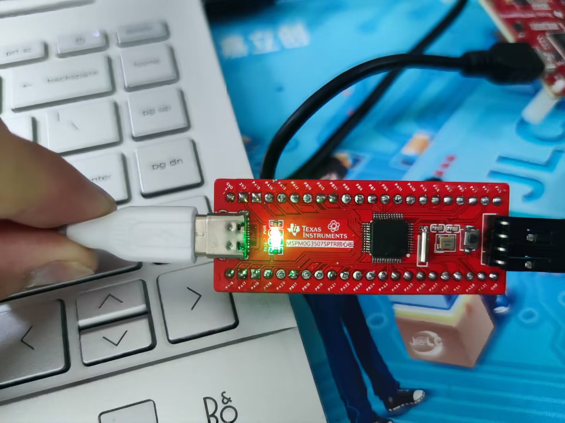
PY32F002AW15U6TR Development Board
PY32 Development Board
I previously designed two boards using the Heco Air001 chipset and felt they were quite good. However, Heco no longer offers free shipping on all its products, and the chips are hard to find, so I was thinking of finding some alternatives.
This board uses the W15U6TR, which doesn't have a boot pin, so it doesn't support direct Arduino serial download. However, you can use SWD to burn the Arduino-compiled image
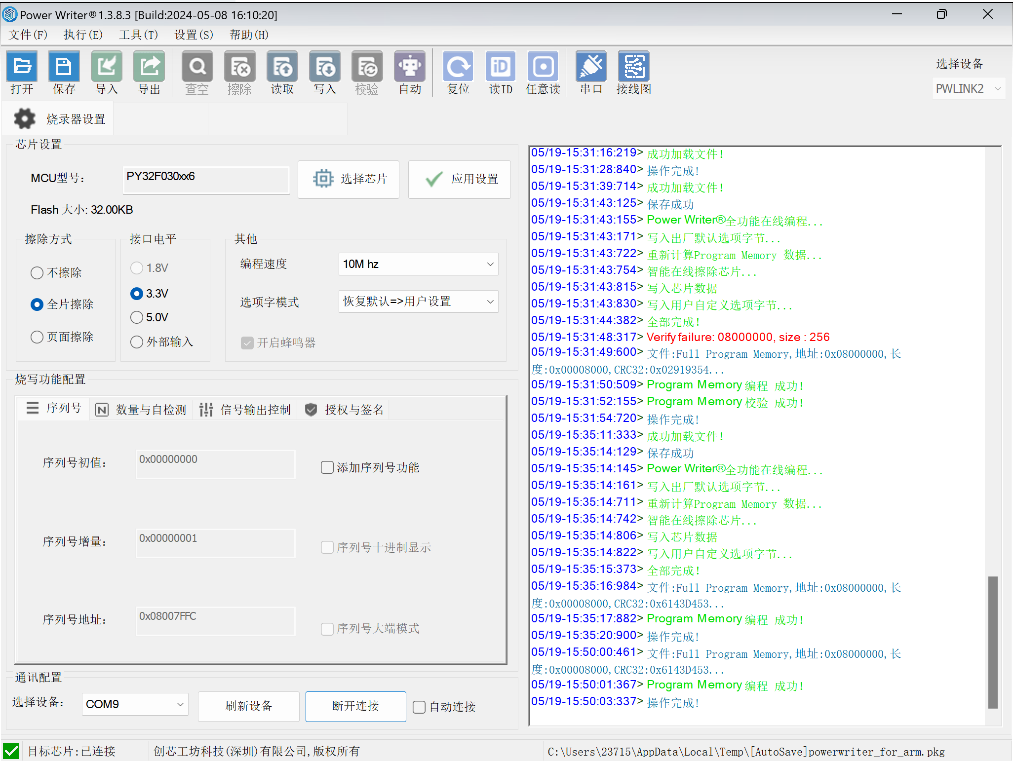
using PWLink, selecting the PY32F030X6 chip. It works similarly to the Air001

. I've tested the OLED program for the Arduino Air001 and the LED flashing program for the Keil Air001, and there haven't been any problems.
VID_20240518_140827.mp4
petal_20240519_165754.mp4
PDF_PY32F002AW15U6TR development board.zip
Altium_PY32F002AW15U6TR development board.zip
PADS_PY32F002AW15U6TR development board.zip
BOM_PY32F002AW15U6TR Development Board.xlsx
94704
Based on the [Taishanpai Development Board] Pocket Computer Project
5-inch LCD screen with touch, 1280*720 resolution, 4000mA battery
I. Hardware Description
1.1 Display Screen Description
The display screen used in this project is model FR0500H30111-A, which was leftover from a previous project, and a purchase link could not be found.
2.1 Speakers: 4Ω/3W, Battery: 4000mA.
II. Software Description
The MIPI driver is attached.
5-inch mobile phone assembly.STEP
Interior photo.jpg
Front view photo.jpg
tspi-rk3566-dsi-v10.dtsi
Functional video.mp4
PDF_Based on the 【Taishanpai Development Board】Pocket Computer Project.zip
Altium_Based on the [Taishanpai Development Board] Pocket Computer Project.zip
PADS_Based on the 【Taishanpai Development Board】Pocket Computer Project.zip
BOM_Based on the [Taishanpai Development Board] Pocket Computer Project.xlsx
94705
AD/DA converter board
The AD/DA conversion circuit adapted for STM32 and FPGA
has been verified.
The AD/DA conversion circuit adapted for STM32 and FPGA has been verified.
See the attached datasheet for
ADS807
DAC902.
dac902.pdf
ADS807_datasheet.pdf
PDF_AD-DA Conversion Board.zip
Altium AD/DA converter board.zip
PADS_AD_DA converter board.zip
BOM_AD_DA Conversion Board.xlsx
94706
Smart terminals based on the Taishan School
Smart terminals based on the Taishan School
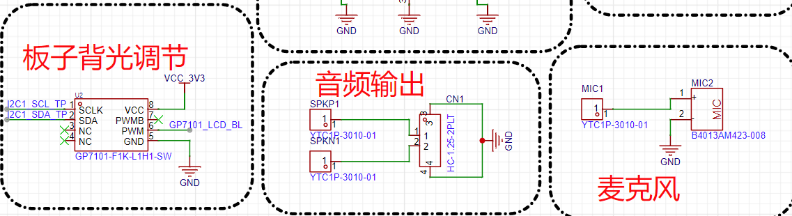
The expansion board, as analyzed in the project principle analysis,
mainly consists of an interface conversion circuit, a backlight circuit, and an audio circuit. 1.
3.1-inch screen MIPI interface;

2. Taishanpai MIPI screen interface;

3. Touch interface

; 4. Backlight
circuit: The backlight circuit is divided into two paths: the first path is output from Taishanpai, and the second path is the onboard backlight driver output, selected by four 0-ohm resistors. If (R103 and R104) are attached but (R105 and R106) are not, the Taishanpai backlight circuit provides power; otherwise, (R105 and R106) are attached but (R103 and R104) are not, and the onboard backlight driver circuit provides power.
The 3.1-inch screen used can only support a maximum backlight current of 25mA. Directly connecting it to the screen risks burning it or causing it to overheat. Therefore, we default to not attaching (R103 and R104) and attaching (R105 and R106) to use the onboard backlight driver for power.

5. Other
video demonstrations:
The expansion board has been verified to function completely normally.
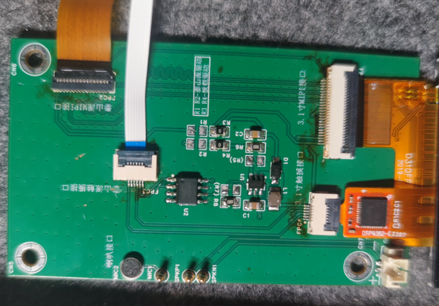

See the attached demonstration video.
a6a384d7260c2490c42d473856c42f38.mp4
c1be64c4cef51651a8e37ec7ff1c367e.mp4
PDF_Smart Terminal Based on Taishan School.zip
Altium_Smart Terminal Based on Taishanpai.zip
PADS_Smart Terminal Based on Taishanpai.zip
BOM_Based on Taishanpai Smart Terminal.xlsx
94707
RT7272 Synchronous Buck Module (3.3V Output)
RT7272 Synchronous Buck Transformer Module (3.3V Output)
Vin = 4.5V - 30V
Vout = 3.3V
Iout(max) = 2.5A
Efficiency > 90% (1A)
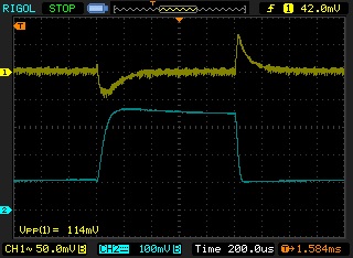
RT7272 Synchronous Buck Module (3.3V Output): Vin=4.5V-30V, Vout=3.3V, Iout(max)=2.5A .
Output ripple

diagram, efficiency vs. output current
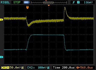
diagram. Load dynamic response test conditions: Vin=12V; Vout=3.3V; Iout=0.8A -> 2.5A -> 0.8A; dI=3A/us; CH1=VOUT; CH2=IOUT.
RT7272B verification board test data.xlsx
PDF_RT7272 Synchronous Buck Module (3.3V Output).zip
PADS_RT7272 Synchronous Buck Module (3.3V Output).zip
BOM_RT7272 Synchronous Buck Module (3.3V Output).xlsx
94708
TPS5430 Solution Verification Board (5V Output)
TPS5430 solution verification board (5V output):
6.3V-30V input/
output, 5V/3A (MAX).
TPS5430 solution verification board (5V output)
ripple voltage: 18mV (Iout=1A)
Efficiency >90% (1A)

Graph Efficiency vs Output Current
Graph Load Dynamic Response Test Conditions: Vin=12V; Vout=5V; Iout=1A -> 3A -> 1A; dI=3A/us; CH1=VOUT; CH2=IOUT
TPS5430 verification board test data.xlsx
PDF_TPS5430 Solution Verification Board (5V Output).zip
Altium_TPS5430 solution verification board (5V output).zip
PADS_TPS5430 Solution Verification Board (5V Output).zip
BOM_TPS5430 Solution Verification Board (5V Output).xlsx
94709
ESP32C3 Miniature Version
An ultra-small core board (21mm x 40mm) made using the ESP32C3.
This system
uses the ESP32-C3FN4 chip, which has 4MB of built-in storage, eliminating the need for external FLASH.
Except for the pins connected to the FLASH, all other GPIOs are brought out, including GPIO11.
For the CLC section on the antenna side, only L1 needs a 0R resistor.
The USB connector is reversible; one side connects to C3, and the other to CH340X. Reversible connection is important.
I bought C3 for only 3.99 RMB in March 2024; it's now over 5 RMB.
Update
2024-04-27: Added version two, removed the CH340X circuit, and changed the USB connection to reversible.
2024-05-03: Optimized some routing, connecting the CH340X's DTR pin in series with the BOOT to prevent DTR pin damage.
2024-05-16 :
Using AT firmware to test the signal, with the phone and ESP connected to the same Wi-Fi network and located close to each other, the phone displayed around -60dBm, while C3 fluctuated within -65dBm, and the Wi-Fi connection was fast.
The incorrect silkscreen printing on the buttons has been corrected; both the CH340 and the buttons have resistors connected in series, and no damage was found to the DTR pin after several days of use.
Errata:
Due to the low power of the LDO, a delay function needs to be added to the loop when using the WebServer.
When using the WiFi function, the WiFi power must be limited; otherwise, the system will crash.
Other brands of C3 can be used without limiting the power, the reason is unclear.
The maximum usable setting tested is: WiFi.setTxPower(WIFI_POWER_13dBm);
I
generally don't read the comments section; if I can't replicate it, there's nothing I can do. Don't
ask why this or that design is necessary; please copy and paste to make
malicious comments and I will delete
the physical product.

PDF_ESP32C3 Mini Version.zip
Altium_ESP32C3 Mini Version.zip
PADS_ESP32C3 Mini Version.zip
BOM_ESP32C3 Mini Version.xlsx
94710
electronic


 京公网安备 11010802033920号

 415-43-219-41-001000


