entire production process was learned by following the Taishanpai documentation and Bilibili videos.
Video link: [Linux Mobile Phone Driver Debugging] LCSC Taishanpai RK3566 Linux Development Board Training Camp Lesson 8_Bilibili_bilibili
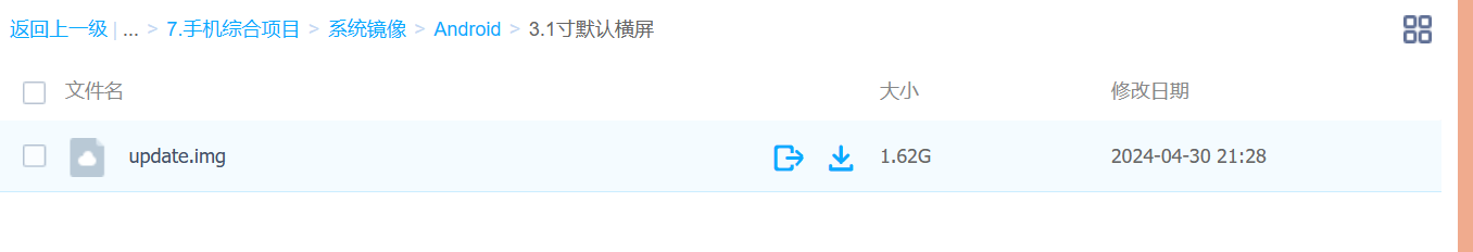
Document link: VII. Mobile Phone Comprehensive Project - Feishu Cloud Documents (feishu.cn)
Many members of the mobile phone production group encountered numerous problems during this project. Here, I will briefly explain my approach to solving them.
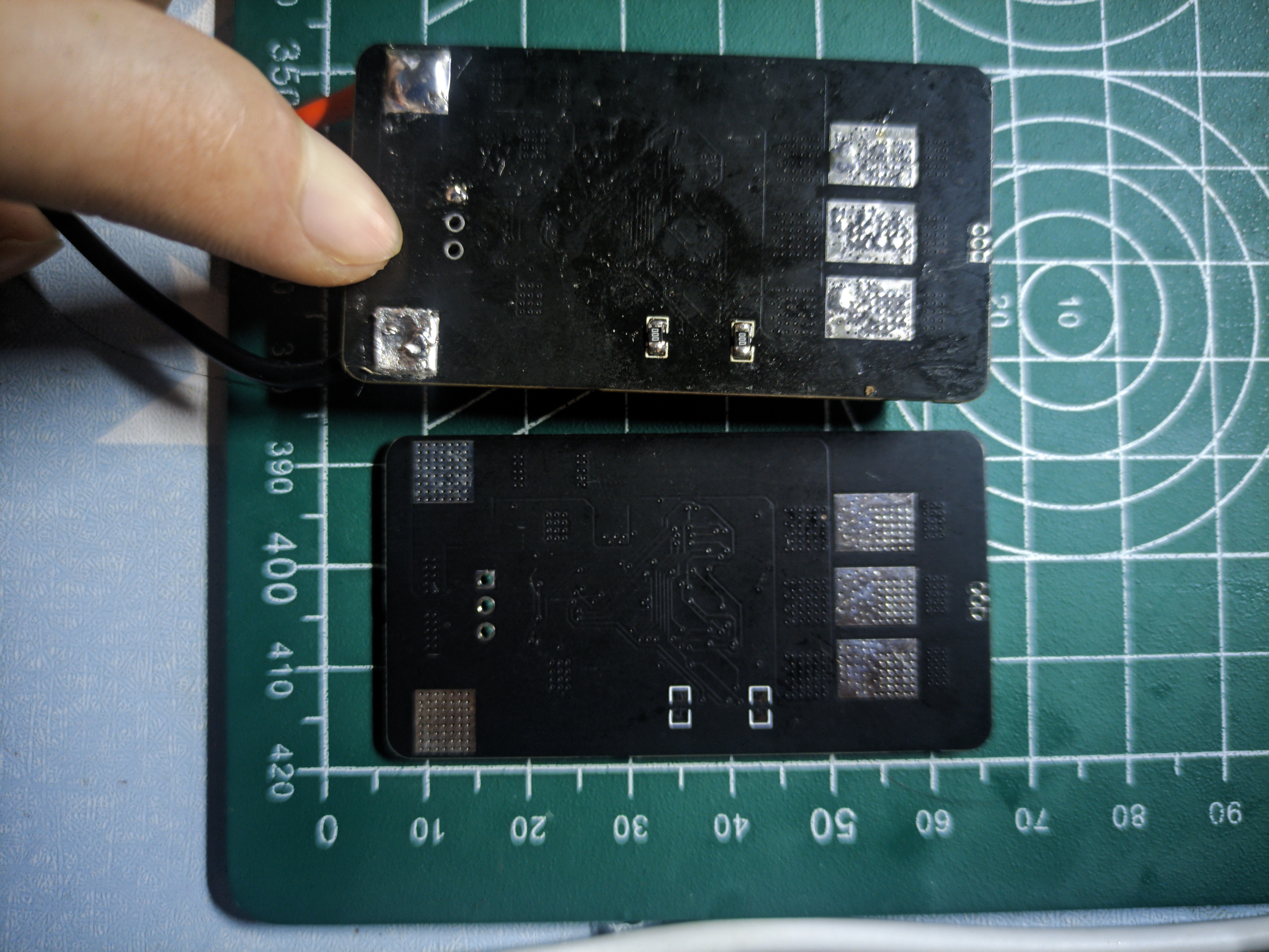
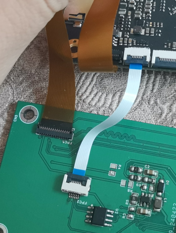
After soldering the board, first check for short circuits between power and ground. My experience with over a dozen chips tells me this is crucial. If everything is fine, flash the firmware. Connect the touchscreen to the development board and power it on to see if there is a backlight. If there is no backlight, check the touchscreen interface for cold solder joints
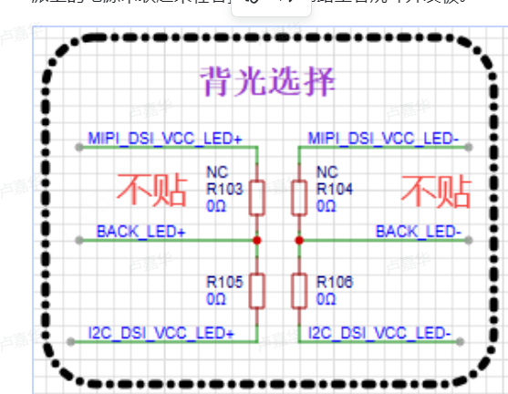
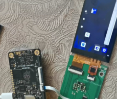
. If there are no cold solder joints , check the backlight selection for problems . That's all the backlight issues I had with my board resolved; the backlight is now working. Connecting the MIPI interface, the screen displays nothing. According to the schematic, the expansion board has no extra circuitry and connects directly to the development board via a terminal block. This leads to three possibilities: a loose connection in the terminal block, a faulty development board, or a faulty screen. Why the possibility of a faulty screen? I previously encountered a similar issue with a screen on a Liangshanpai game console where the backlight was on but there was no display. Replacing the screen fixed it. Considering the cost of trial and error, I resoldered two terminals and powered it on. Horizontal lines appeared, and I didn't know how to fix them. Reconnecting the touch panel cable and the MIPI interface cable resolved the issue.
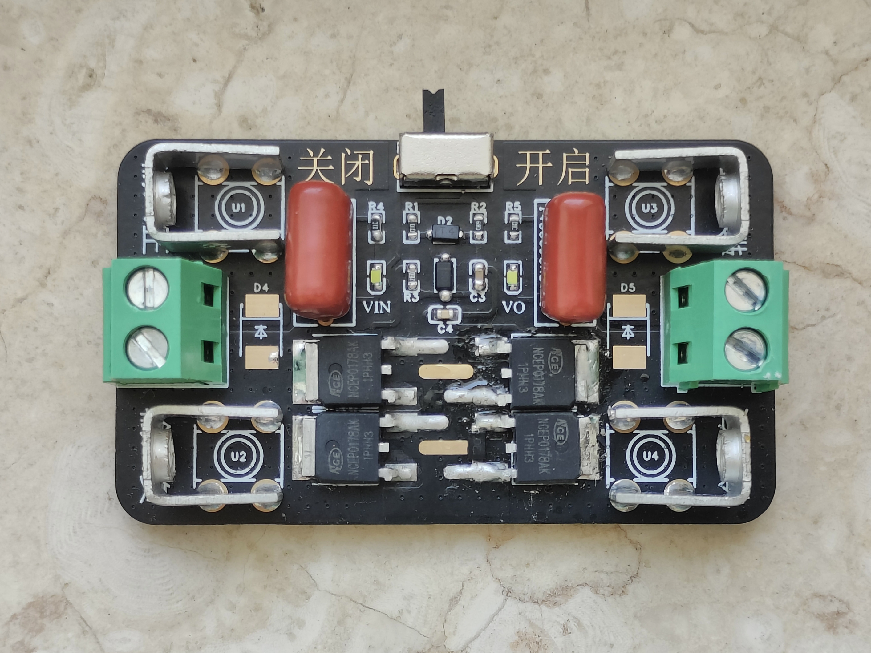
The soft starter switch prevents arcing upon power-on and also provides reverse connection protection.
Usage instructions : Do not exceed
the
MOSFET's withstand voltage. The MOSFET I used is NCEP0178AK, with a nominal internal resistance of 8.5mΩ. Note that overvoltage and overcurrent can cause damage; use with caution.
PDF_Soft Starter Switch.zip
Altium_soft_starter_switch.zip
PADS_Soft Starter Switch.zip
BOM_Soft Starter Switch.xlsx
94842
Ultra-small DC-DC converter with built-in inductor, 17V input, 3A output, verified version: TPS82130SILR
Are you still struggling with your DC-DC converter taking up too much PCB space? Try this!
1. Introduction:
A super-small, high-current DC-DC chip.
Detailed technical parameters are available on the TI website.
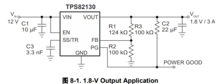
The TPS82130 features an integrated inductor, a 17V input voltage, and a 3A buck converter module.

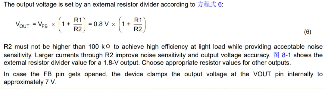
2. Output Voltage Regulation
3. Typical Applications
4. Physical Image.
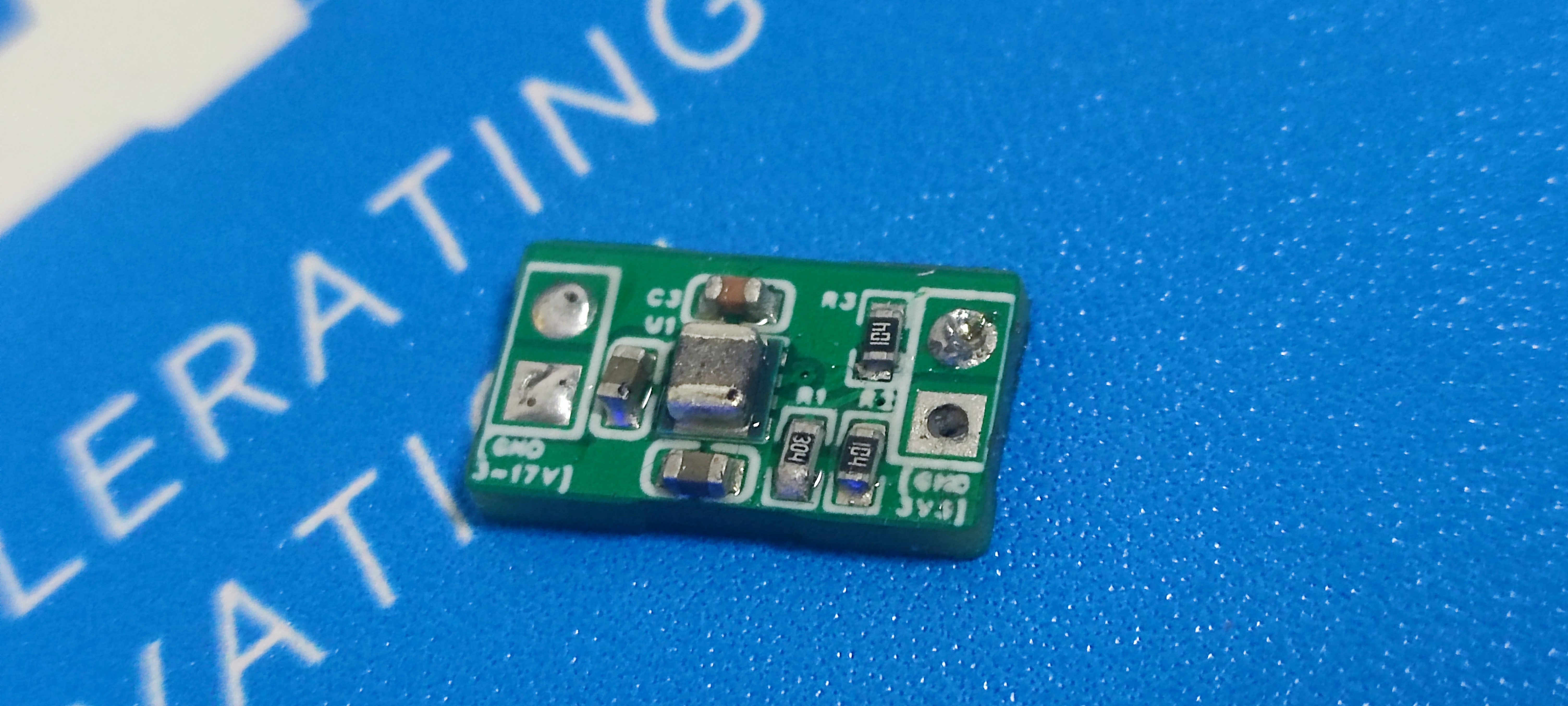
Since I didn't have a 22uf capacitor on hand for the output, I temporarily soldered a 1uf capacitor, resulting in terrible ripple.
PDF_Ultra-small DC-DC converter with built-in inductor, 17V input, 3A output, verification version【TPS82130SILR】.zip
Altium Ultra-Small DC-DC Converter with Built-in Inductor, 17V Input, 3A Output, Verified Version [TPS82130SILR].zip
PADS_Ultra-small DC-DC converter with built-in inductor, 17V input, 3A output, verified version [TPS82130SILR].zip
BOM_Ultra-small DC-DC converter with built-in inductor, 17V input, 3A output, verified version【TPS82130SILR】.xlsx
94843
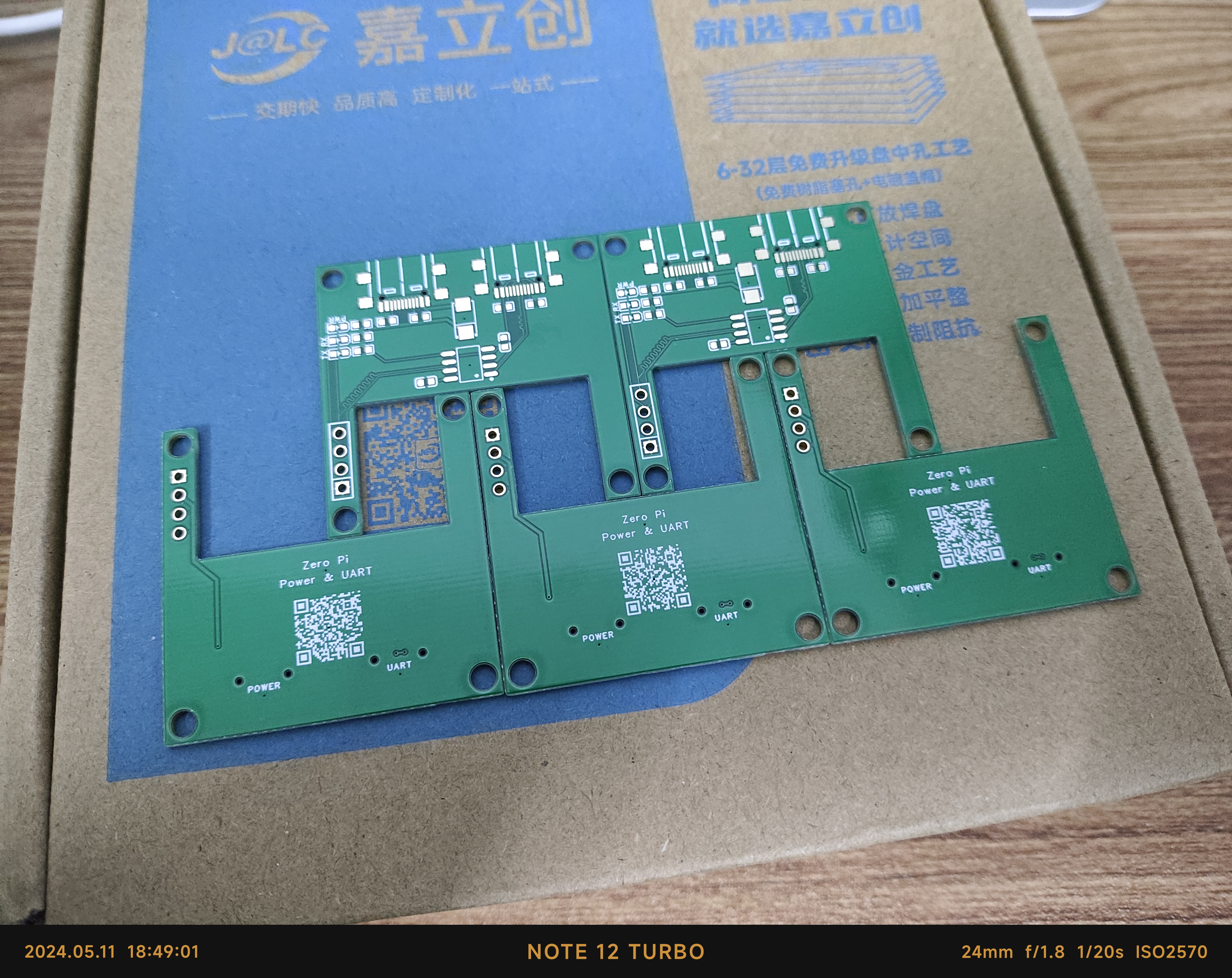
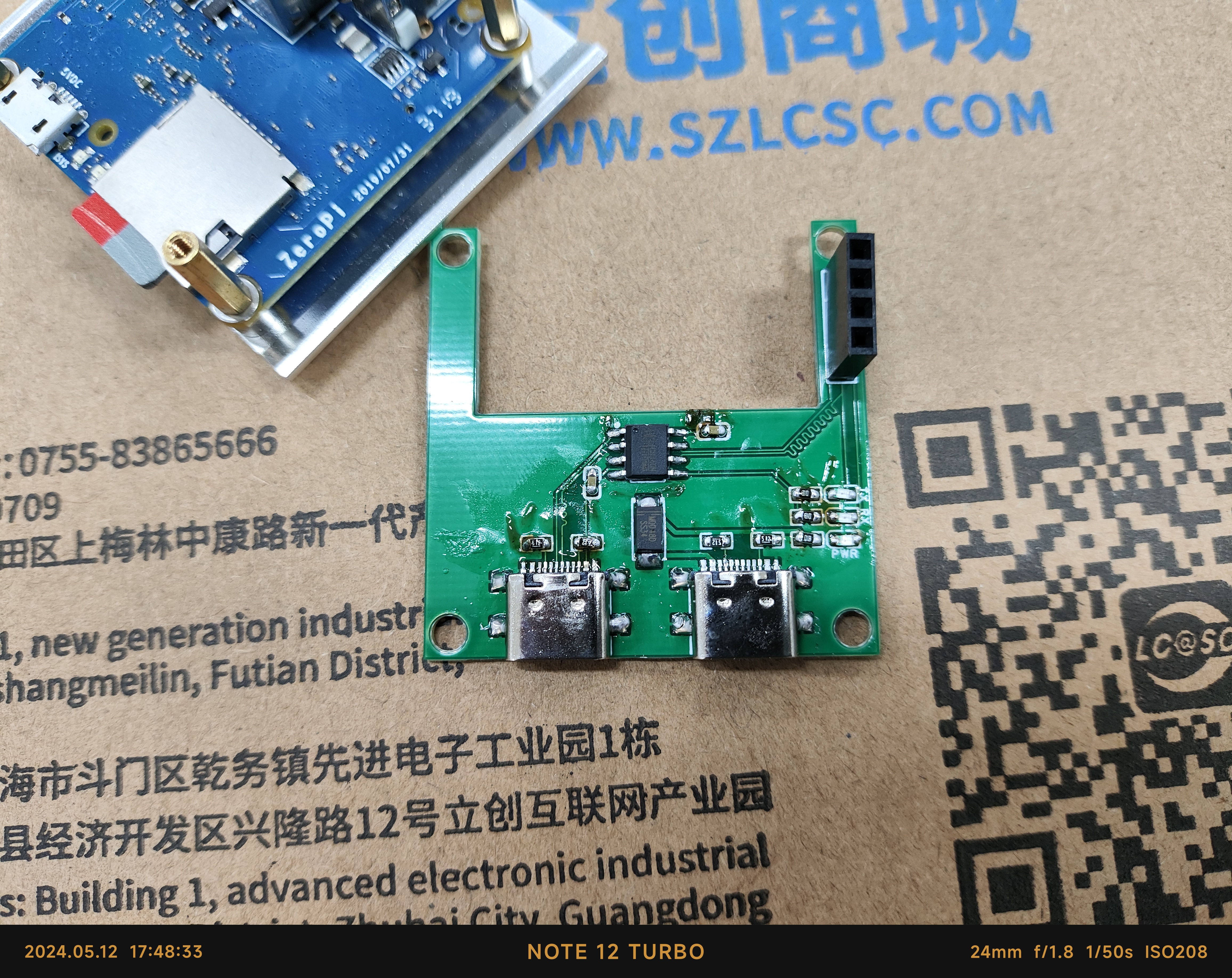
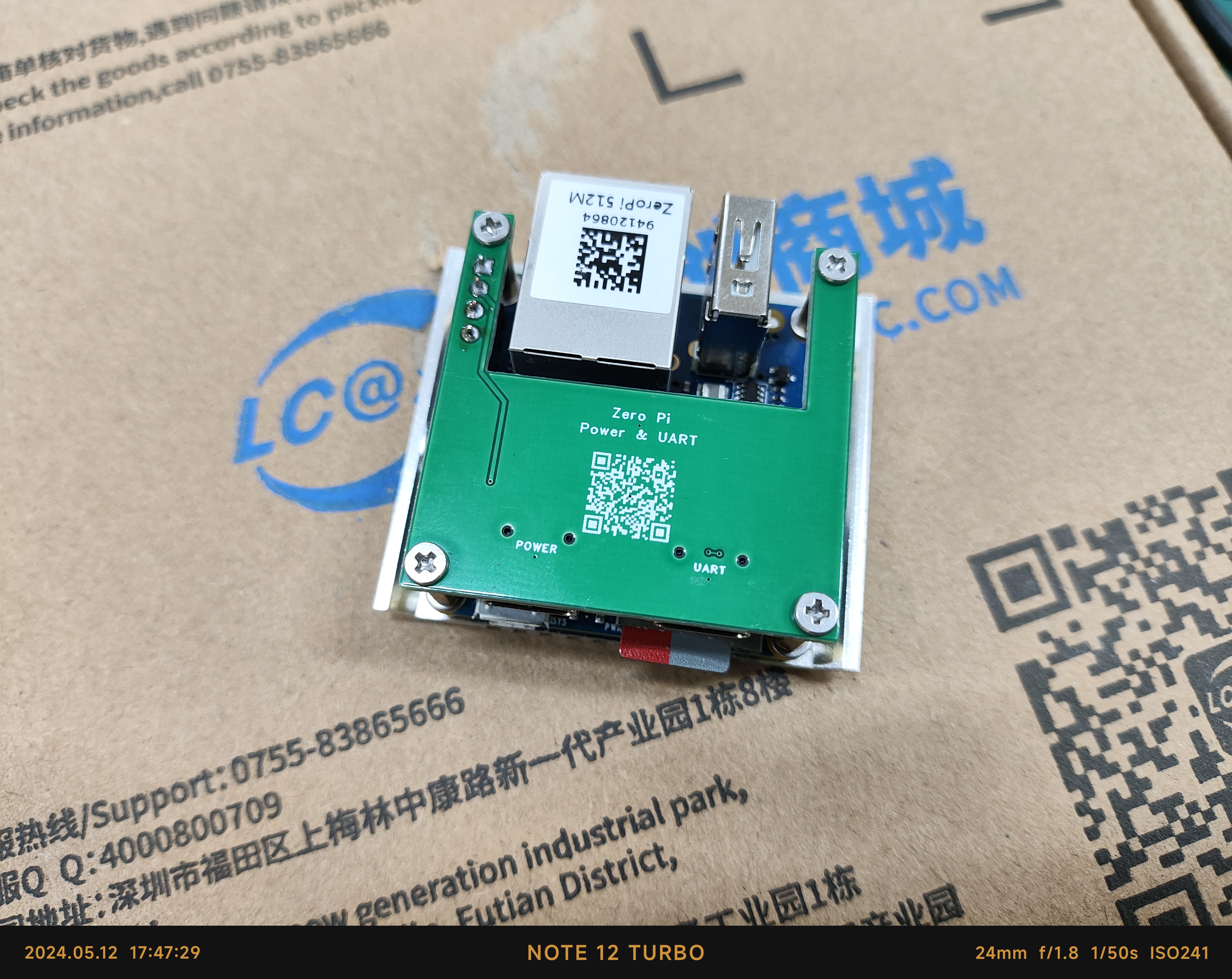
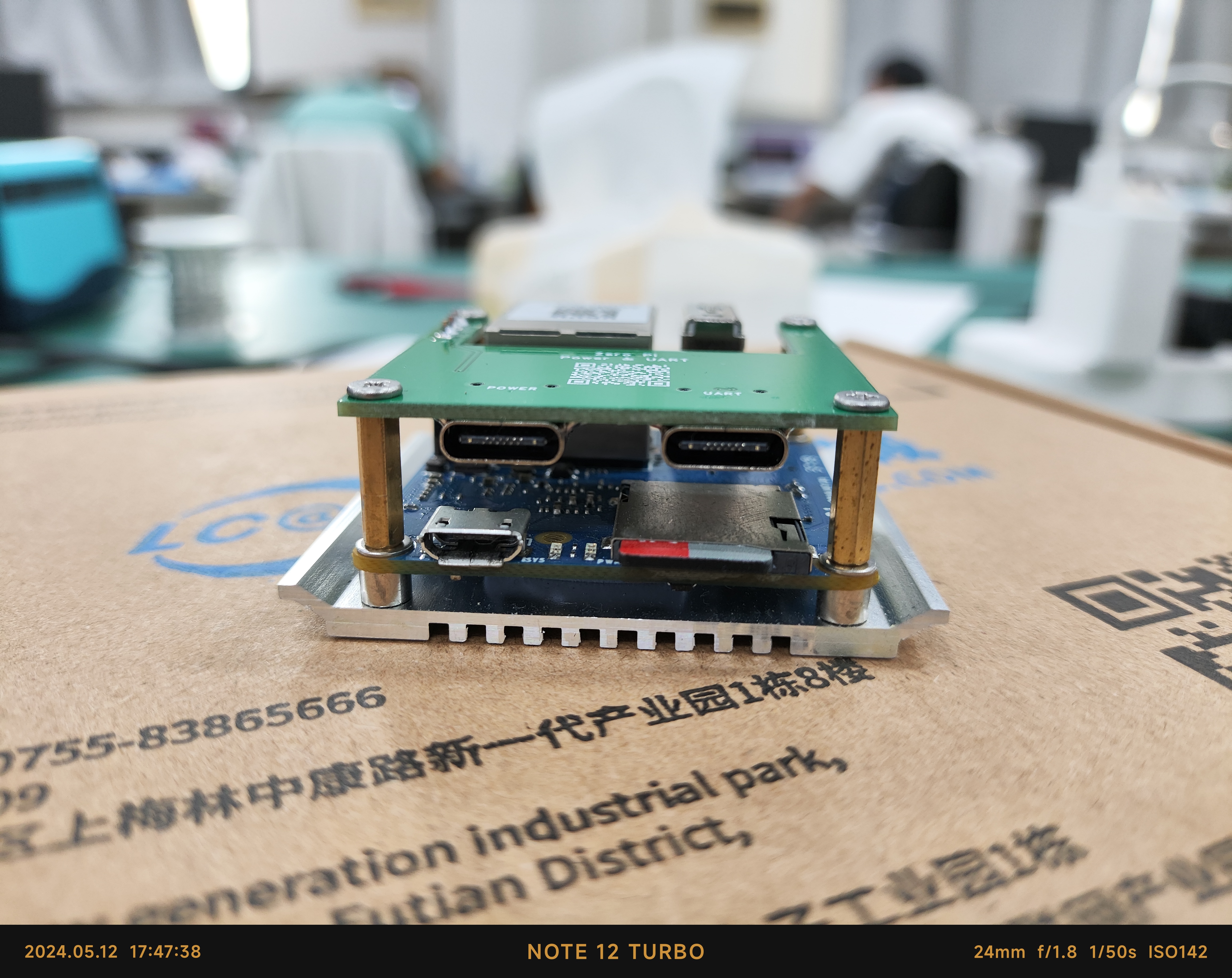
Serial port and power supply board for FriendlyARM ZeroPi
The serial port and power supply board is compatible with FriendlyARM ZeroPi and can be powered via Type-C.
ZeroPi is another completely open-source handheld maker tool launched by the Friendly Electronics team for makers, embedded enthusiasts, electronic artists, and hobbyists. It features an Allwinner H3 quad-core processor, 512MB of RAM, a memory card slot, and a 4-pin debug serial port. The only drawback is that it uses MicroUSB for power, so a small board was designed to power the development board via a Type-C interface through the 4-pin debug serial port. The onboard serial port can be directly used for
pre-built verification. The mounting copper pillars are M2*11+4.
PDF_Serial Port and Power Supply Board for FriendlyARM ZeroPi.zip
Altium serial port and power supply board for FriendlyARM ZeroPi.zip
PADS_Serial Port and Power Supply Board for FriendlyARM ZeroPi.zip
BOM_Serial Port and Power Supply Board for FriendlyARM ZeroPi.xlsx
94844
USON8_4x4mm to 8px2.54PH
USON8 4x4mm to 8p 2.54ph adapter for USON8 programming.
The dedicated jig for the USON8 is very expensive, so I made this EEPROM burning tool for miniaturized devices. Although it's still a bit troublesome, it's at least a feasible solution besides methods like wire bonding.
PDF_USON8_4x4mm to 8px2.54PH.zip
Altium_USON8_4x4mm to 8px2.54PH.zip
PADS_USON8_4x4mm to 8px2.54PH.zip
BOM_USON8_4x4mm to 8px2.54PH.xlsx
94845
ESC (not verified)
ESC module, used in conjunction with a fan.
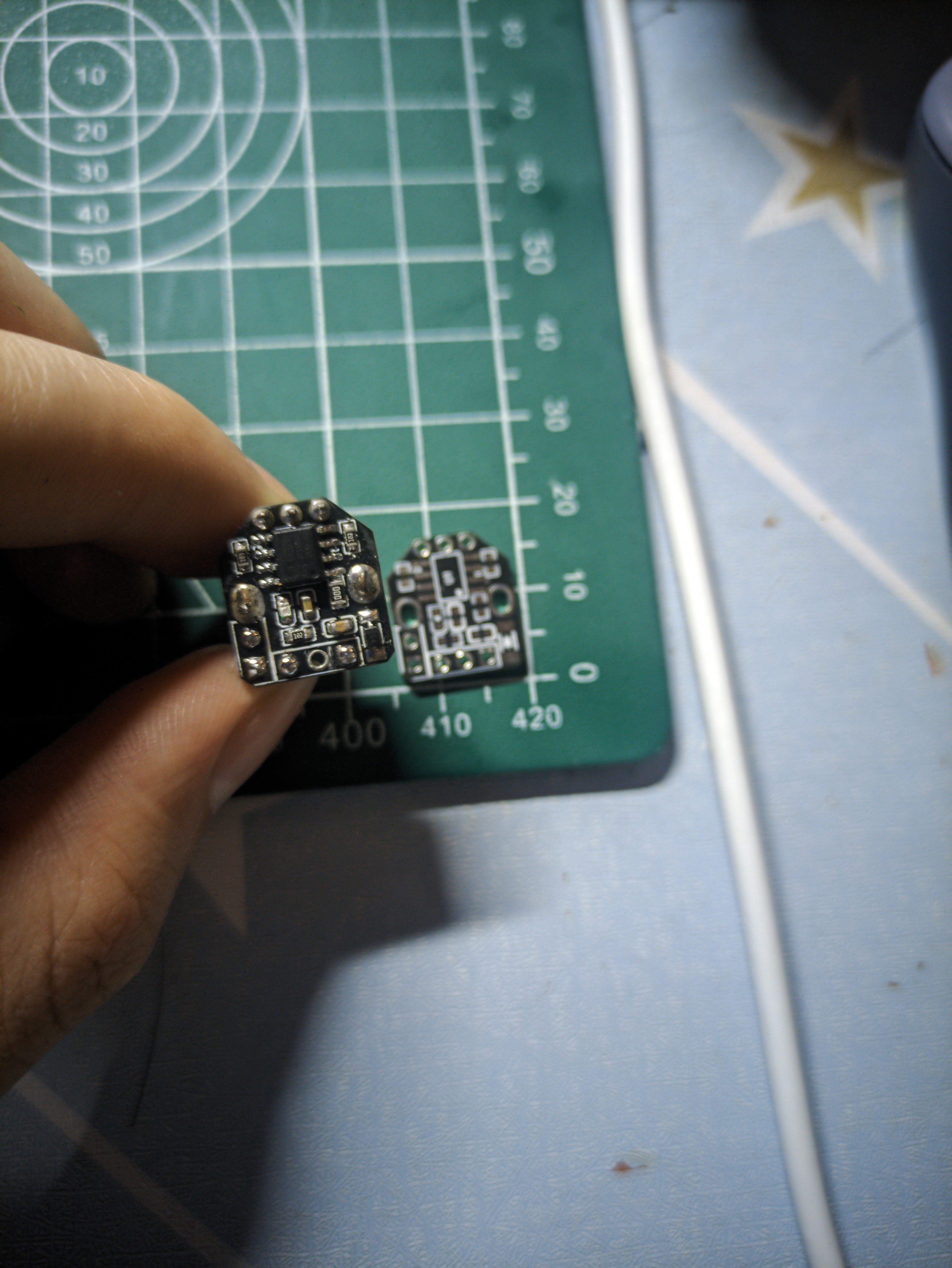
This PCB is for testing purposes only, exploring the feasibility of 3D printing a fan (fan printout address: fan). The PCB design was inspired by a Bilibili video ([FPV Drone] DIY BLHeli_S ESC, Homemade Drone ESC, Recording the Process from Schematic to Firmware Download). The board has been successfully manufactured and soldered. However, it has yet to pass the firmware test. Therefore, this project is currently only for demonstration and exchange. An improved version is expected to be released around summer vacation. At that time, the ESC will be smaller and more perfect. Below are pictures of the actual product.

PDF_Electronic Speed Controller (Unverified).zip
Altium_eScreenEsc (Unverified).zip
PADS_Electronic Speed Controller (Unverified).zip
94846
ESC and PWM output controller
PWM output controller
This project was also intended as a module for fans, but it was eventually cancelled due to time constraints. Like the previous ESC, this module failed verification due to repeated rewriting. It was based on the work of this open-source author (a brushless ESC PWM signal generator), with some size reductions and the addition of an indicator light. Below are some physical demonstration images.
This component is only for demonstration and discussion; future improvements may be made, or it might be integrated with an ESC.
PDF_Electronic Control Screw (ESC), PWM Output Controller.zip
Altium_Electronic Speed Controller (ESC) and PWM Output Controller.zip
PADS_Electronic Speed Controller (ESC) and PWM Output Controller.zip
94847
electronic


 京公网安备 11010802033920号

 MR0028A16PY28F111


