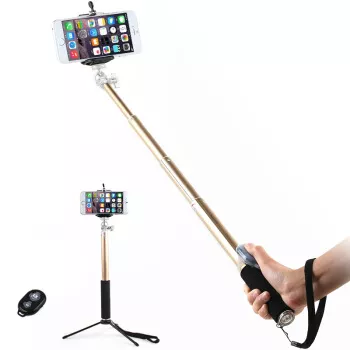
The Bluetooth selfie stick based on Bluetooth technology can take photos from a long distance without worrying about the constraints of wires and other factors. Moreover, this solution does not require a special mobile phone APP and can directly use the Bluetooth connection within the system. This solution is relatively simple in the development, testing, and operation stages, and can be operated quickly. It can be applied to most scenarios and facilitate people's lives.
Hardware resources:
This solution is tested and verified based on the MM32 BLE_Test Board . The Bluetooth selfie stick application only requires one function button on the hardware. The Bluetooth part uses the smallest system controlled by Bluetooth. We connect this button to the PA0 pin of the MCU , which can be used as The wake-up pin is used, and it can also be used as a self-timer function pin.
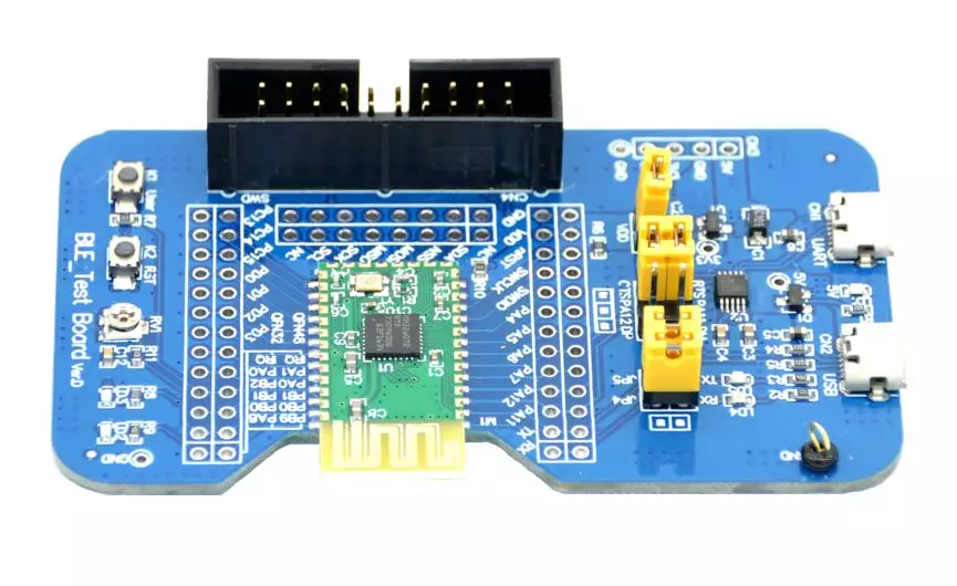
Figure 1 Test development board
Software resources:
Configure PA0 as a pull-down input mode, multiplex the interrupt line to PA0 and configure the external interrupt line interrupt, and finally enable the PWR clock and WakeUp pin. The detailed code is as follows:
do {
GPIO_InitTypeDef GPIO_InitStructure;
RCC_AHBPeriphClockCmd(RCC_AHBPeriph_GPIOA, ENABLE);// Enable GPIOA
GPIO_InitStructure.GPIO_Pin =GPIO_Pin_0; //PA.0
GPIO_InitStructure.GPIO_Mode =GPIO_Mode_IPD;// Pull-down input
GPIO_Init(GPIOA, &GPIO_InitStructure); // Initialize IO
} while(0);
do {
EXTI_InitTypeDef EXTI_InitStructure;
RCC_APB2PeriphClockCmd(RCC_APB2Periph_SYSCFG, ENABLE);// Enable multiplexing function clock
// Use external interrupt method
SYSCFG_EXTILineConfig(GPIO_PortSourceGPIOA, GPIO_PinSource0); // Interrupt line 0 is connected to GPIOA.0
EXTI_InitStructure.EXTI_Line = EXTI_Line0; // Set all external lines of the button
EXTI_InitStructure.EXTI_Mode = EXTI_Mode_Interrupt; // Set external external interrupt mode : EXTI line is interrupt request
EXTI_InitStructure.EXTI_Trigger = EXTI_Trigger_Rising; // rising edge trigger
EXTI_InitStructure.EXTI_LineCmd = ENABLE;
EXTI_Init(&EXTI_InitStructure); // Initialize external interrupt
} while(0);
do {
NVIC_InitTypeDef NVIC_InitStructure;
NVIC_InitStructure.NVIC_IRQChannel = EXTI0_1_IRQn; // Enable the external interrupt channel where the button is located
NVIC_InitStructure.NVIC_IRQChannelPriority = 2; // From priority level 2
NVIC_InitStructure.NVIC_IRQChannelCmd = ENABLE; // Enable external interrupt channel
NVIC_Init(&NVIC_InitStructure); // Initialize the peripheral NVIC register according to the parameters specified in NVIC_InitStruct
} while(0);
RCC_APB1PeriphClockCmd(RCC_APB1Periph_PWR, ENABLE); // Enable PWR peripheral clock
PWR_WakeUpPinCmd(ENABLE); // Enable wake-up pin function
2. We send data to the mobile phone in the gatt_user_send_notify_data_callback function. This function is a callback function. The protocol stack will call back this function (asynchronously) when the system allows it. This function can be used for the Bluetooth module to actively send data. No additions are allowed inside the function. Blocking code. In the Bluetooth selfie stick application, we determine the level status of PA0 in this function . If the button is pressed, the button press information is sent to the mobile phone. The detailed implementation code is as follows:
void gatt_user_send_notify_data_callback(void)
{
if (GPIO_ReadInputData(GPIOA) & 0x01)//press
{
NotifyKey(0x28);
NotifyApplePhoto();
}
}
u8 NotifyApplePhoto(void)//apple photo hid photo capture, hard code
{
u8 Keyarray[5] = {2,0,8,0,0}; //VolUp,hard code
sconn_notifydata(Keyarray,5);
Keyarray[2] = 0;
sconn_notifydata(Keyarray,5);
return 1;
}
u8 NotifyKey(u8 KeyIdx)//hid standard keyboard key, hard code
{
u8 Keyarray[9] = {1,0,0,0,0,0,0,0,0};//0xa1
Keyarray[3] = KeyIdx;
sconn_notifydata(Keyarray,9);
Keyarray[3] = 0;
sconn_notifydata(Keyarray,9);
return 1;
}
We directly use the Bluetooth function that comes with the mobile phone for testing. The operation process is as follows:
1. Turn on the Bluetooth of your phone and enter the Bluetooth control interface, search for the selfie stick Bluetooth device.
2. Select the Bluetooth device with the corresponding name ( MindMotion-Shutter ) and pair it.
3. After successful pairing, open the camera interface of the mobile phone. At this time, click button K1 to take pictures.
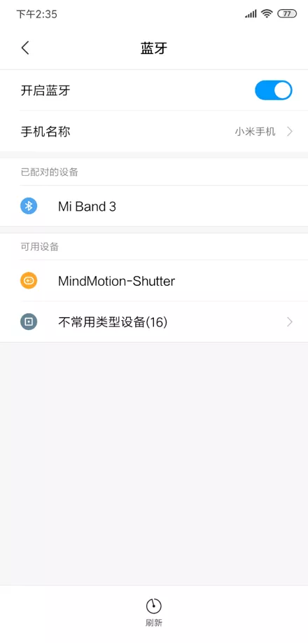
Figure 2 Mobile phone interface
All reference designs on this site are sourced from major semiconductor manufacturers or collected online for learning and research. The copyright belongs to the semiconductor manufacturer or the original author. If you believe that the reference design of this site infringes upon your relevant rights and interests, please send us a rights notice. As a neutral platform service provider, we will take measures to delete the relevant content in accordance with relevant laws after receiving the relevant notice from the rights holder. Please send relevant notifications to email: bbs_service@eeworld.com.cn.
It is your responsibility to test the circuit yourself and determine its suitability for you. EEWorld will not be liable for direct, indirect, special, incidental, consequential or punitive damages arising from any cause or anything connected to any reference design used.
Supported by EEWorld Datasheet
EEWorld
subscription
account

EEWorld
service
account

Automotive
development
community

Robot
development
community

About Us Customer Service Contact Information Datasheet Sitemap LatestNews


Room 1530, 15th Floor, Building B,
No.18 Zhongguancun Street,
Haidian District,
Beijing, Postal Code: 100190
China
Telephone: 008610 8235 0740
 京公网安备 11010802033920号

 2170264