When using a breadboard for LED learning, the WS2812 LEDs, when powered by the microcontroller via USB, could not function properly when there were many LEDs.
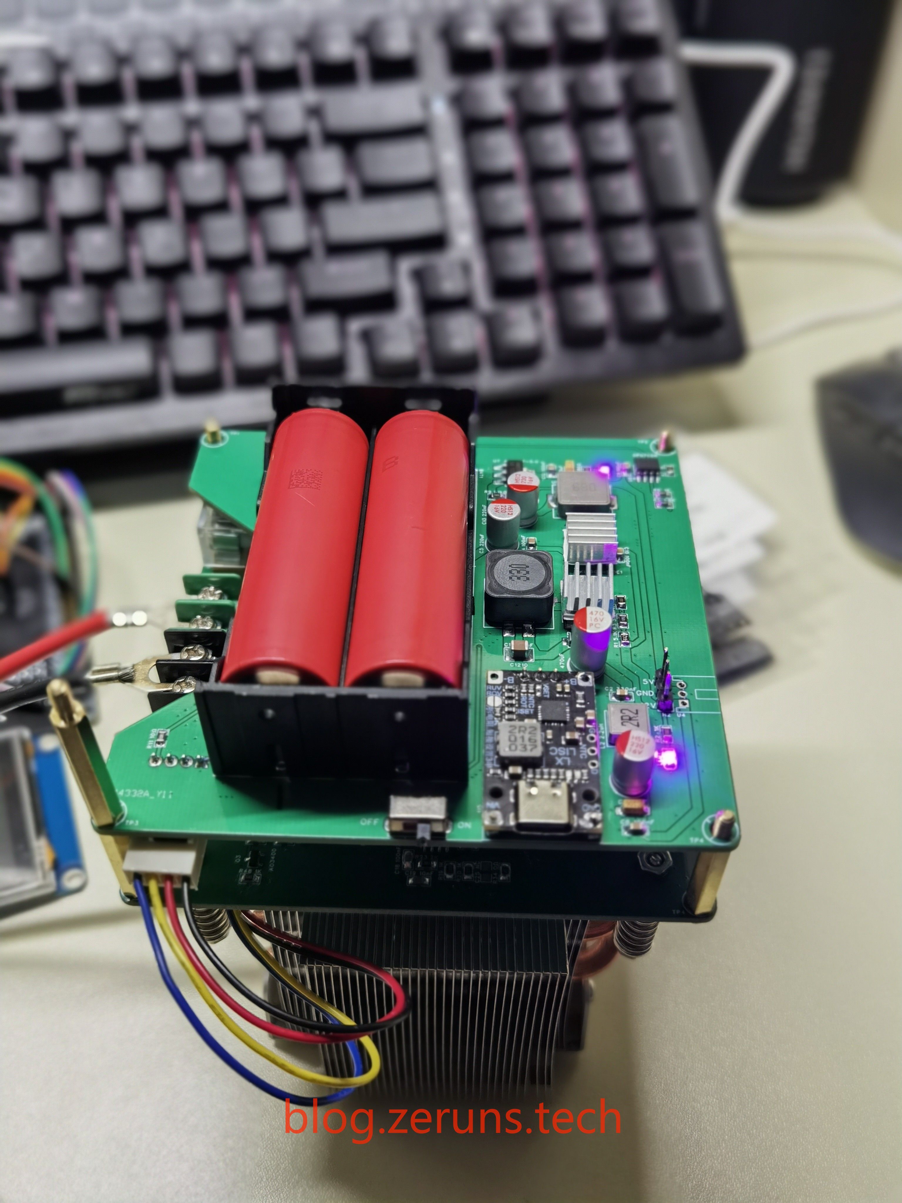
Ready-made power supply modules available online were too rudimentary and posed a risk of unstable power supply. Therefore, a custom power supply module was created to simultaneously meet the 3.3V power requirements of the microcontroller and the 5V power requirements of the LEDs.
using a TI LMR14050SDDA as the main BUCK IC, supporting 40V input (36V is marked on the PCB for safety reasons due to bare board use).
The default output is 3A, with a 5A max output (note the need for heat dissipation).
The 5V power supply is then stepped down to 3.3V using an LDO to power the microcontroller or other 3V3 modules. An older 1117 chip from an older school was used, and a toggle switch was included to adjust the output voltage.
Since the design goal is to power lights, the load varies considerably. Therefore, I used through-hole capacitors and surface-mount capacitors for voltage regulation after the BUCK circuit. If there are no heavy load scenarios during use, the 47uF capacitor can be omitted.
input power board at 5V showed normal operation (a slight voltage error was due to the feedback resistor tolerance).
Switching to 3.3V via a switch also resulted in normal operation.
Reference Design:
Cat FOC - JLCPCB EDA Open Source Hardware Platform (oshwhub.com)
Leica Triangle - V3 - Motor 3205 Version - JLCPCB EDA Open Source Hardware Platform (oshwhub.com)
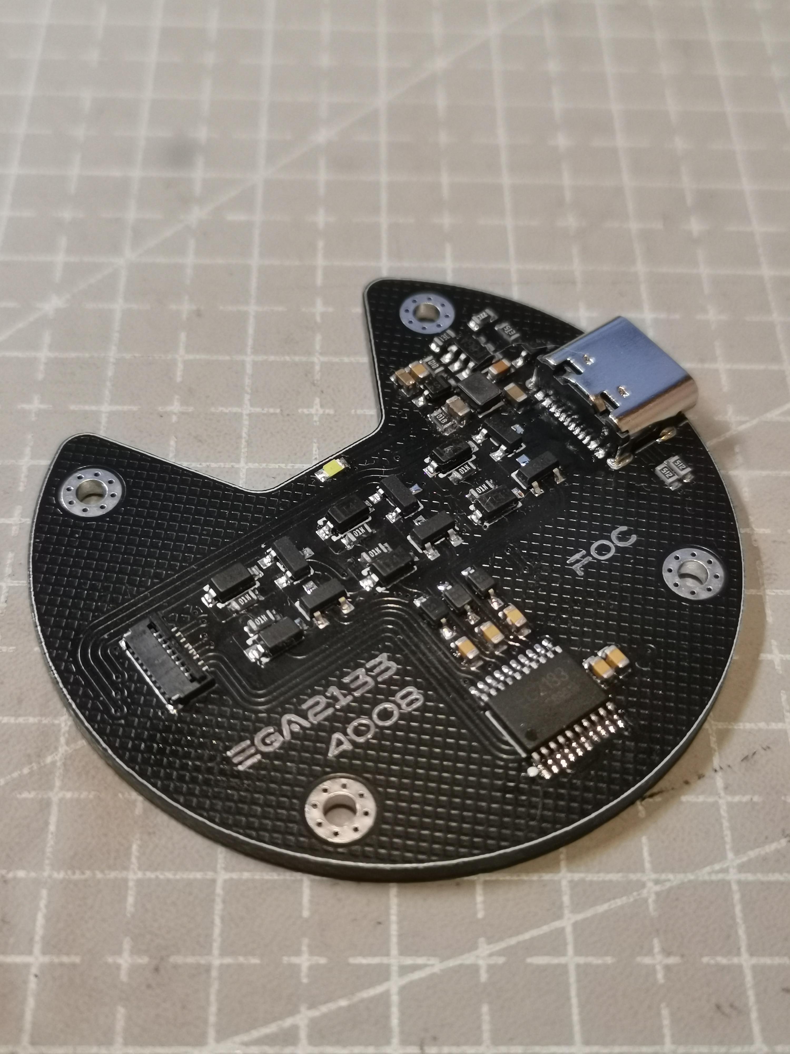
I. Hardware Design
1. Driver IC: EG2133;
2. Buck IC: MP2359;
3. Magnetic Encoder: AS5600-ASOM
II. Notes
1. This design is for PCB layout and soldering only; it has not been connected to a motor for verification.
2. The FB resistor for MP2359 can be replaced with a different model, which is marked on the schematic.
3. If the Type-C input voltage is greater than 12V, it is recommended to replace the R10 43k resistor with a 13.3k resistor. Currently, the 43k resistor is only used to start the buck converter when the input is 5V.
4. The MP2359 buck converter directly connects to the corresponding pin of the FPC socket at 3.3V. There is no reverse current protection design. Please note!
III. Physical Images
PDF_EG2133-based 4008 motor FOC driver board.zip
Altium_EG2133-based 4008 motor FOC driver board.zip
PADS_EG2133-based 4008 motor FOC driver board.zip
BOM_4008 Motor FOC Driver Board Based on EG2133.xlsx
94911
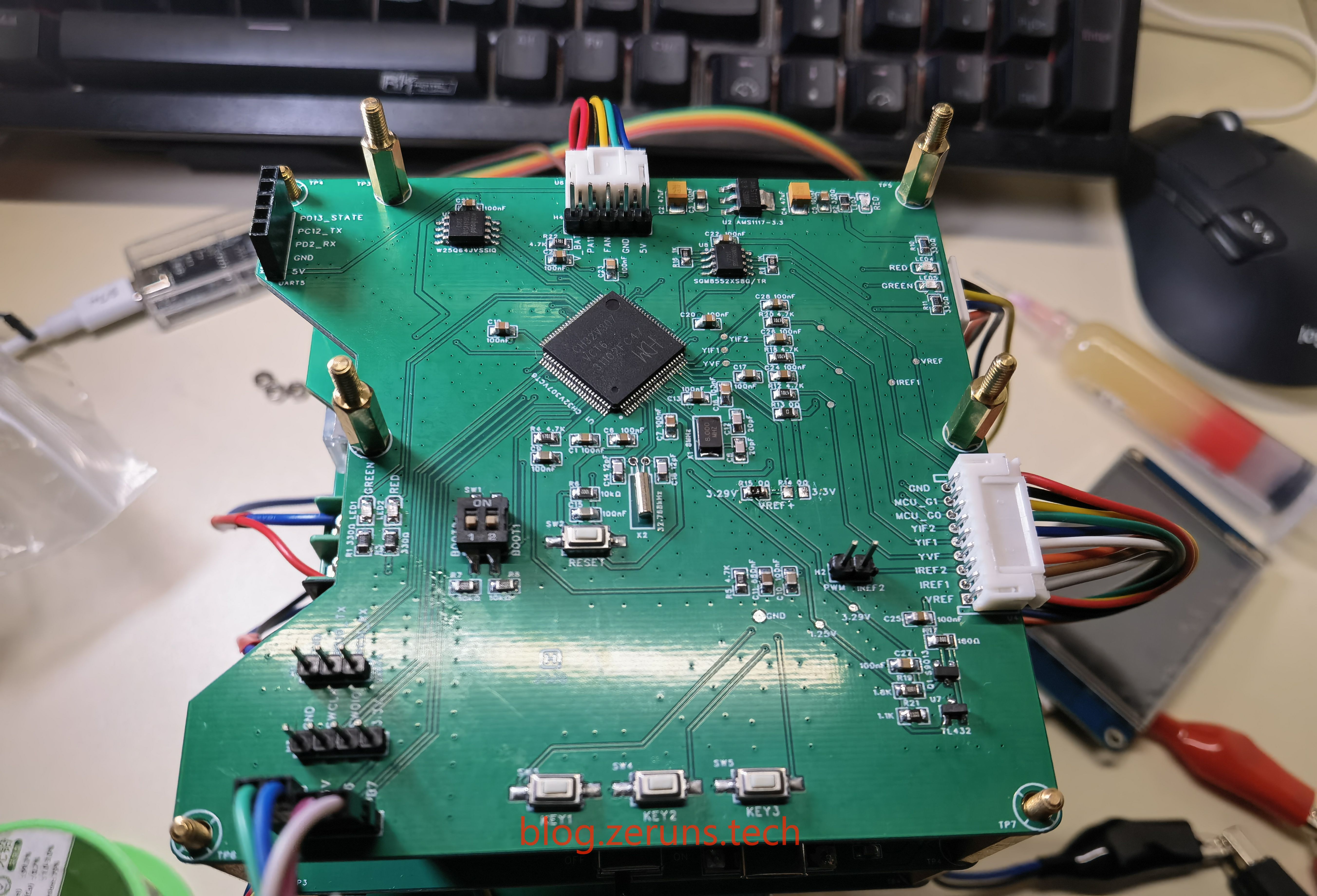
An open-source intelligent electronic load based on CH32V307, an embedded systems competition entry.
An open-source intelligent electronic load based on CH32V307VCT6, an embedded system design competition entry, is available, including schematics, PCB layout, source code, and a project report. This entry was submitted
to the 2023 Embedded Chip and System Design Competition, application track, and received a national second-place ranking.
This is an open-source intelligent electronic load based on the CH32V307VCT6, an embedded systems competition entry. It includes schematics, PCB layout, source code, and a project report. It
was a National Second-Level entry in the 2023 Embedded Chip and System Design Competition, application track.
It was modified from a previous Holtek version of the electronic load, ported to the CH32 microcontroller, and uses the RT-Thread system. Some code optimizations were made. It was rushed and is not very good; please don't criticize too harshly.
Demo video: https://www.bilibili.com/video/BV1Zu4y1m7Zd/
Open-source intelligent electronic load based on HT32F52352, Holtek Cup entry: https://blog.zeruns.tech/archives/784.html
This open-source project is for reference and learning purposes only; replication is not recommended. There are many more, better, and more complete open-source electronic load projects on the LCSC open-source platform!
Electronics/Microcontroller Technology Exchange Group: 820537762
You can apply for free development board samples on the Qinheng official website: https://url.zeruns.tech/h9a99
What is an Electronic Load?
An electronic load is an electronic device used to simulate a real load environment to test the performance of a power supply or electronic circuit. Compared to traditional passive loads such as high-power adjustable resistors or heating wires, electronic loads have many advantages, such as adjustable parameters and ease of use. Whether for professional electronic engineering projects or amateur electronics enthusiasts, an electronic load tester is an essential piece of equipment.
Electronic loads can be divided into AC electronic loads and DC electronic loads based on the type of power supply they test. Functionally, common types include constant current, constant voltage, constant resistance, and constant power. Because most power supplies we commonly see are constant voltage DC power supplies, the main test for this type of power supply is its current output capability. Therefore, in most application scenarios, DC constant current electronic loads are the most common type. Electronic loads can also be divided into two types based on their control method: numerical control and analog. Compared to electronic loads controlled by purely analog circuits, CNC electronic loads use digital control, making parameter adjustment more intuitive. They also offer richer functionality, simpler expansion, and convenient automation of testing.
Project Overview:
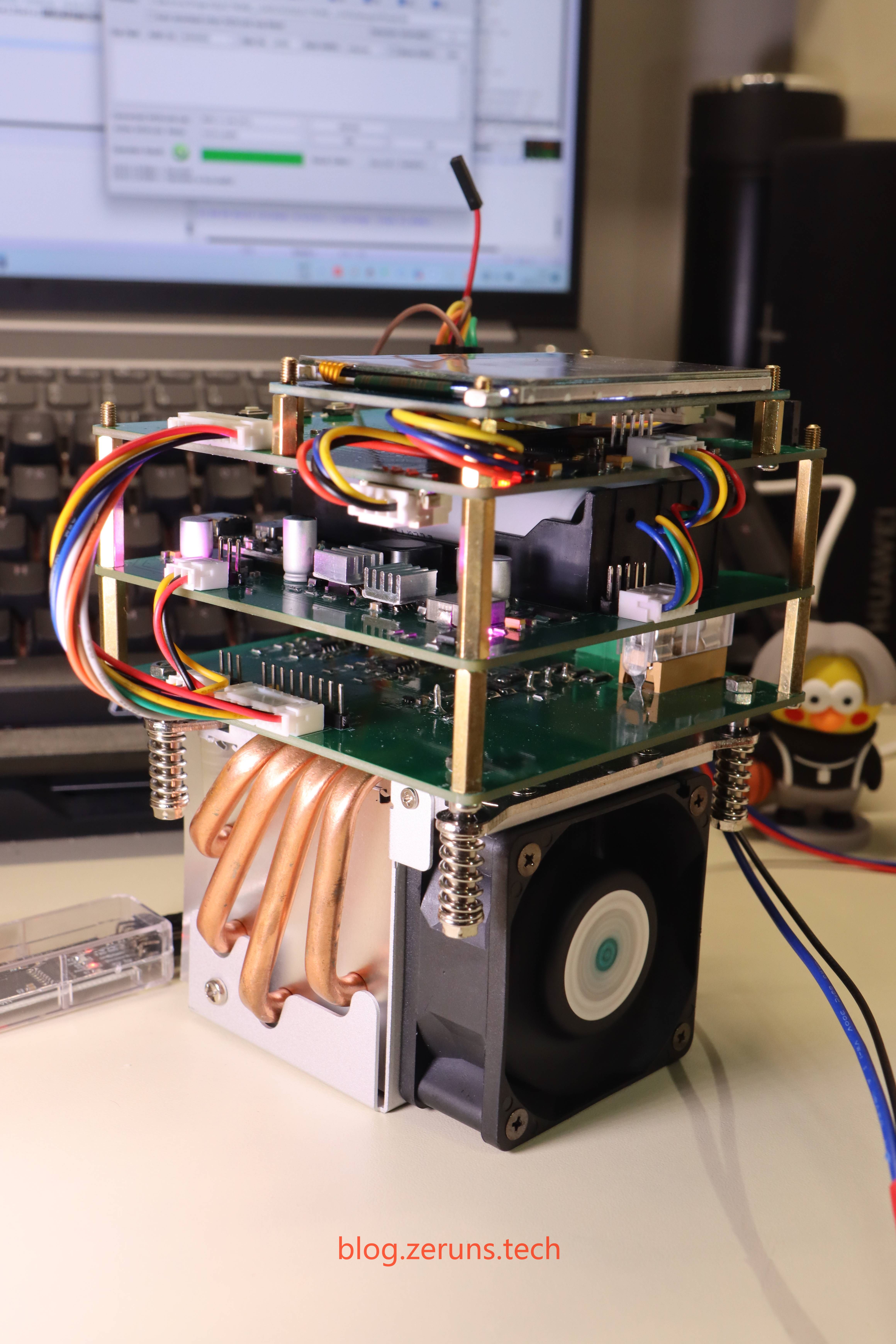
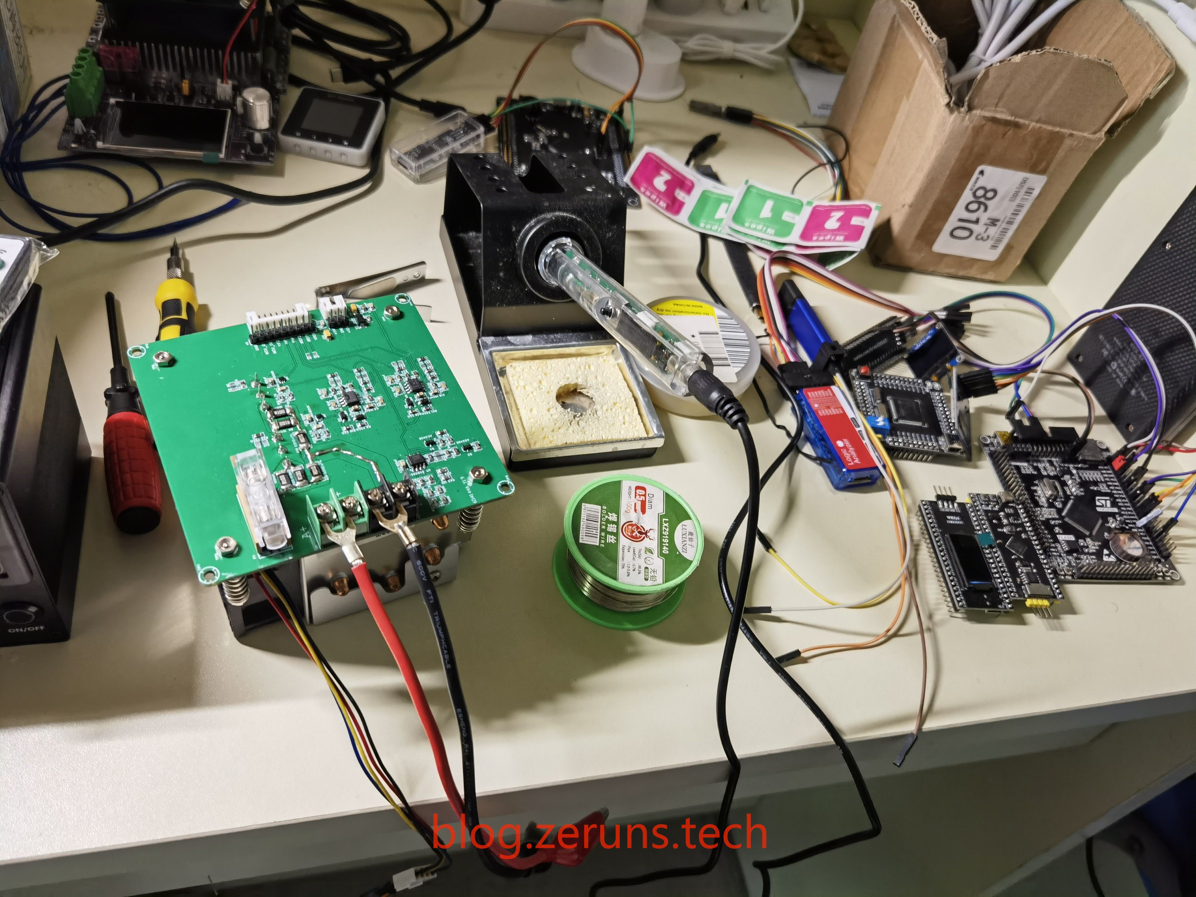
This project uses the CH32V307VCT6 Qinheng microcontroller as the main control chip for its electronic load design. It is powered by an 18650 lithium battery for easy portability.
The control method involves the microcontroller's DAC outputting a DC voltage as a reference voltage, which is compared with the voltage after current/voltage sampling and amplification by the operational amplifier. The operational amplifier output controls the MOSFET, thus achieving constant voltage/constant current.
The touchscreen is a 2.8-inch serial port screen from Taojingchi, model TJC3224T028_011R.
The heatsink is a 1356/1366-pin side-blowing heatsink from a 2U server.
The project program was developed using RT-Thread Studio. The circuit design used LCSC EDA software.
The maximum input voltage and current is 100V/10A, and the maximum power is 200W. I didn't take many photos
of the actual product
at the time, so I only found these few. You can check out the demo video.

The download
links below contain: circuit schematics, LCSC EDA project files, PCB fabrication files, program source code, serial port screen project files, and chip manual.
123 Cloud Drive Unlimited Speed Download Link: https://www.123pan.com/ps/2Y9Djv-6NevH.html
Baidu Cloud Drive Download Link: https://pan.baidu.com/s/17YSlBZ6F1M18k7JGa7FlVA?pwd=buxx Extraction Code: buxx
Component Purchase Links
: CH32V307VCT6 Chip: https://s.click.taobao.com/T8MSZot
CH32V307VCT6 Development Board: https://s.click.taobao.com/2JBSZot
INA199A1 Chip: https://s.click.taobao.com/XLuweot
0805 SMD Resistor Sample: https://s.click.taobao.com/p8YSGpt
0805 SMD Capacitor Sample: https://u.jd.com/9uvZoBd
XL1509 chip: https://s.click.taobao.com/DOcRZot
Serial port screen: https://s.click.taobao.com/pyzleot
It is recommended to purchase components from LCSC Mall: https://activity.szlcsc.com/invite/D03E5B9CEAAE70A4.html
Other recommended open-source projects:
A three-phase power acquisition device has been made and open-sourced for easy monitoring of home electricity usage: https://blog.zeruns.tech/archives/771.html
An STM32F407 standard library project template with a ported U8g2 graphics library: https://blog.zeruns.tech/archives/722.html
Qinheng CH32V307VCT6 minimum system board open source: https://blog.zeruns.tech/archives/726.html
LM25118 automatic buck-boost adjustable DC-DC power module: https://blog.zeruns.tech/archives/727.html
The EG1164 high-power synchronous rectification boost module is open source, with a maximum efficiency of 97%: https://blog.zeruns.tech/archives/730.html
A 4G environmental monitoring node based on the Zeruns Air700E (data on temperature, humidity, air pressure, etc.) uploads data to the Alibaba Cloud IoT platform via MQTT: https://blog.zeruns.tech/archives/747.html
PDF_Open Source Intelligent Electronic Load Based on CH32V307, Embedded Competition Entry Open Source.zip
Altium_Intelligent Electronic Load Based on CH32V307 Open Source, Embedded System Competition Entry Open Source.zip
PADS_Intelligent Electronic Load Based on CH32V307 Open Source, Embedded System Competition Entry Open Source.zip
BOM_Open Source Intelligent Electronic Load Based on CH32V307, Embedded System Competition Entry.xlsx
94912
The Arduino ornithopter flight control panel - PYJ-FK-Supermini-ATmega328P-V1.2, weighing only 0.26g.
Hardware Solution Overview: This is a minimal system development board based on the ATMEGA328P-MMHR, with an ultra-small size of 10mm × 10mm. The board integrates a 5V, 1A LDO. Originally designed for flight control of a micro ornithopter, it also integrates an SBUS reverse circuit.
Weighing only 0.26g, this Arduino ornithopter flight control board is open source!!
1. **Disclaimer:** This small open-source solution was actually developed a long time ago, but I felt it was somewhat unnecessary to release it before. I thought people with some hardware experience wouldn't need or even consider this open-source solution, and complete beginners would be better off buying a ready-made one. Therefore, fearing criticism from both experts and beginners (please, both sides, have mercy!), I kept putting it off. However, I did promise fans in previous video comments and private messages to open-source this hardware, and considering the needs of the Butterfly project from Mechatronics, weight reduction is still very meaningful, so I decided to release it for those who need it, hoping it can help those who require it.
2. **Hardware Solution Introduction:** This is a minimal system development board based on the ATMEGA328P-MMHR, with an ultra-small size of 10mm×10mm. The board integrates a 5V, 1A LDO, supporting 2S~3S lithium battery input (2S lithium battery recommended). Since it was initially designed for flight control of a micro ornithopter, an SBUS reverse circuit was also integrated. Two versions of the board were designed and prototyped, both supporting hardware interfaces and both ISP and serial port download methods (the newly prototyped board requires ISP download of the bootloader; you can search for specific download methods yourself).
① One version has all pins exposed through 1.27mm pitch half-hole pads, suitable for use as a micro Arduino development board in applications with extremely limited space;
② The other version exposes only some pins: serial port, SPI programming pins, and two multi-function I/O ports, suitable for micro ornithopters. PB3 and PB4 can be used to control the two servos of the ornithopter, and PB5 can be used as the PPM signal input. SBUS pin pads are also exposed.
3. Instructions for Use:
① This is an open-source hardware project; even a simple one requires some basic hardware and software knowledge. If you encounter any problems, please search for solutions yourself first. Thank you.
② The board has been tested and the program can be programmed successfully. You can search for specific methods yourself.
③ This is just a hardware solution. If you're using it as a flight control system for an ornithopter, you'll need to find open-source servo ornithopter control code online and modify the PWM output pin and PPM input pin.
④ Regarding the code: Last year, I initially referenced code from a Japanese netizen. There are now many versions online with PPM signal input modified from his code; please search for them yourself (so please don't ask me for the code, I don't have it! I don't have it! I don't have it!). Currently, our code has been completely refactored. The hardware is based on ESP32, and the code uses both SBUS and ESPNOW protocols, so we no longer use PPM (few channels, not resistant to interference). We will also be removing the independent signal receiver soon (sorry, these are not currently open source! So please don't ask me! Please don't ask me! Please don't ask me! Thank you! Thank you! Thank you!).
⑥ If you have read the above information and can use this open-source hardware solution, here are a few helpful tips that I hope will be of assistance.
⑦ Regarding programming, please search for keywords like "Arduino boot loader programming" for specific programming methods. You can use a 1.27 probe programming clip or soldered cables.
⑧ Why make it so small and light? Because for a micro ornithopter, extreme weight reduction is necessary (weigh a few butterflies or bees and you'll understand). Even a 0.1g reduction is significant! So please, if you use this solution, do not use: 2.54 header pins! Do not use servo connectors! Do not use JST 2.54 power connectors! Do not use thick silicone wires! ... All that hard work to reduce weight will be wasted if you use the wrong header pins or connectors. Weigh every component, cable, and connector.
⑨ You can try JST 1.25 air-to-air connectors for power connectors; for motors and servos, just solder the wires directly. You can use 30AWG silicone wire or suitable soft enameled wire (the kind used for headphones).
PYJ-FK-supermini-ATmega328P-V1.2-Open Source Hardware Description.pdf
PDF_Arduino Ornithopter Flight Control Board Weighing Only 0.26g - PYJ-FK-Supermini-ATmega328P-V1.2.zip
Altium_Arduino Ornithopter Flight Control Board Weighing Only 0.26g - PYJ-FK-supermini-ATmega328P-V1.2.zip
PADS - Arduino Ornithopter Flight Control Board Weighing Only 0.26g - PYJ-FK-supermini-ATmega328P-V1.2.zip
BOM_Arduino Ornithopter Flight Control Board Weighing Only 0.26g - PYJ-FK-Supermini-ATmega328P-V1.2.xlsx
94913
arduino-fingernail_2024-02-22_19-28-29
An Arduino development board, smaller than a fingernail and weighing only 0.3g! (Open source hardware) This may be the smallest Arduino development board you can find!
Arduino development board, smaller than a fingernail, weighing only 0.3g! (Open source hardware), this might be the smallest Arduino development board you can find!
1. Disclaimer: This small open-source solution was actually developed a long time ago, but I felt it was somewhat unnecessary to release it before! I thought that people with some hardware experience wouldn't need or even consider this open-source hardware solution, and complete beginners would be better off buying a ready-made one. Therefore, fearing criticism from both experts and beginners (please, both gods, have mercy!), I kept putting it off. However, I did promise fans in previous video comments and private messages to open-source this hardware, and considering the needs of the Butterfly project from Mechatronics, weight reduction is still very meaningful, so I decided to release it for those who need it, hoping it can help those who require it.
2. Hardware Solution Introduction: This is a minimal system development board based on the ATMEGA328P-MMHR, with an ultra-small size of 10mm×10mm. The board integrates a 5V, 1A LDO, supporting 2S~3S lithium battery input (2S lithium battery recommended). Since it was initially designed for a micro ornithopter flight control system, an SBUS reverse circuit is also integrated. Two versions of the board were designed and prototyped, both supporting hardware interfaces and both ISP and serial port download methods (the newly prototyped board requires ISP method to download the bootloader; you can search for specific download methods yourself).
① One version has all pins brought out through 1.27mm pitch half-hole pads, suitable for use as a micro Arduino development board in space-constrained applications;
② The other version only brings out some pins: serial port, SPI programming pins, and two multi-function I/O ports, suitable for micro ornithopters. PB3 and PB4 can be used to control the two servos of the ornithopter, and PB5 can be used as the PPM signal input. SBUS pin pads are also brought out.
3. The prototype board has been simply verified; programming works correctly. See the attachment for details!
PYJ-FK-supermini-ATmega328P-V1.2-Open Source Hardware Description.pdf
PDF_arduino-fingernail_19-28-29.zip
Altium_arduino-fingernail_19-28-29.zip
PADS_arduino-fingernail_19-28-29.zip
BOM_arduino-fingernail_2024-02-22_19-28-29.xlsx
94914
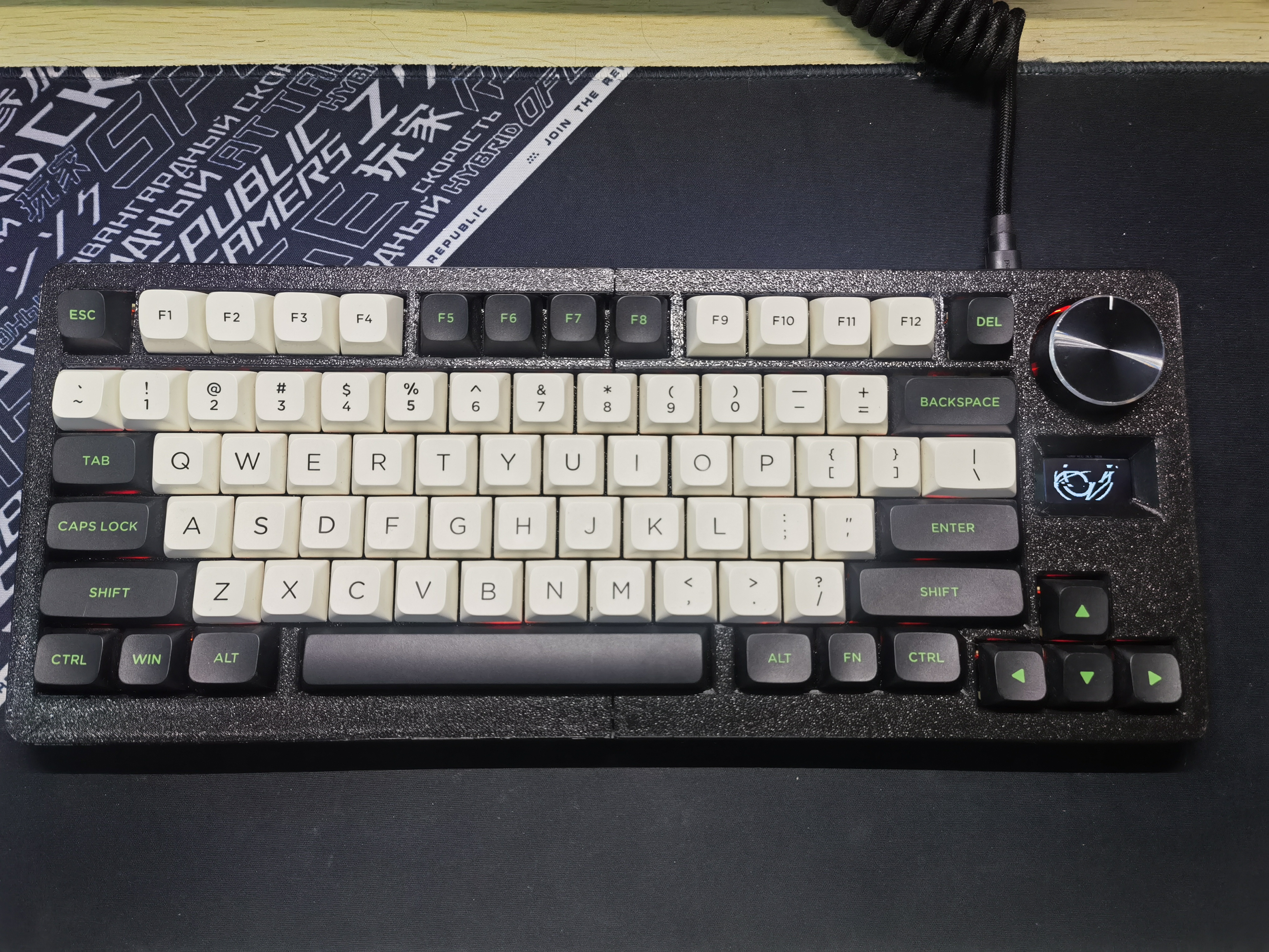
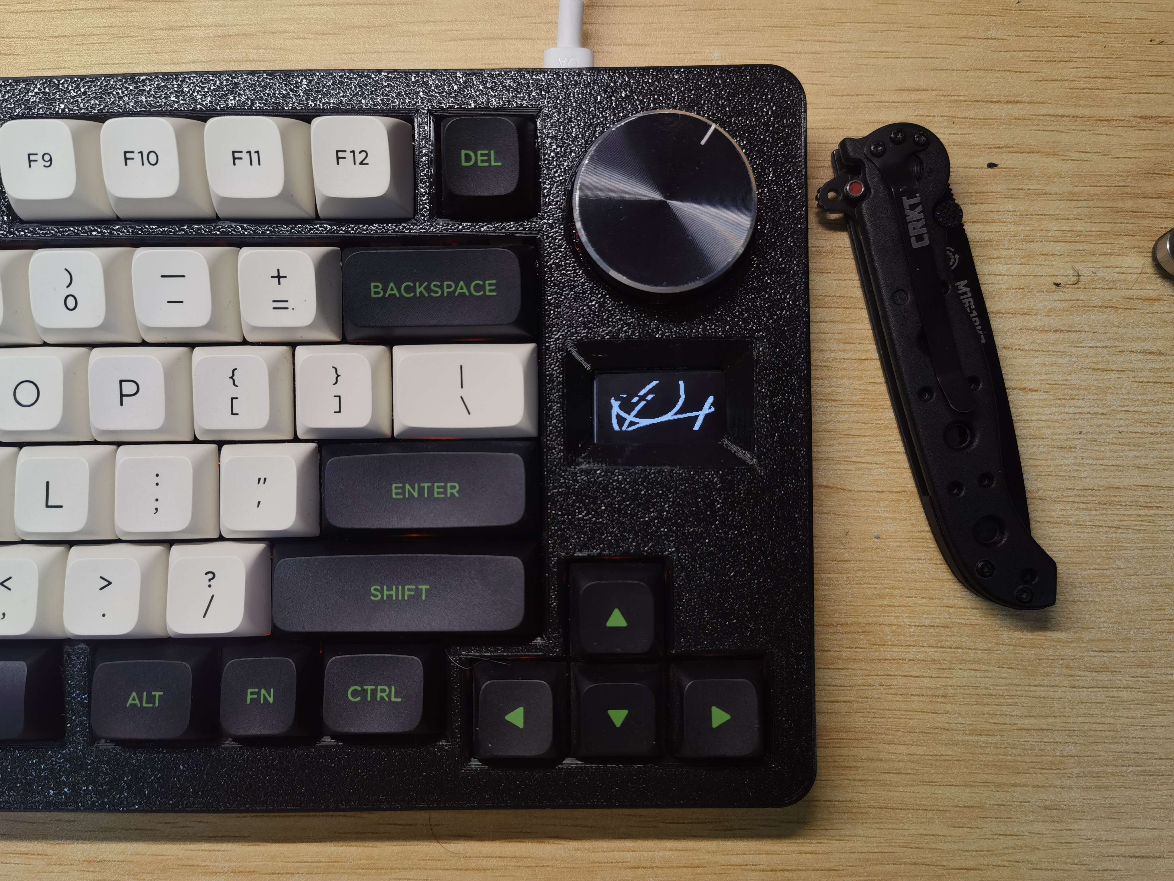
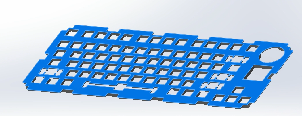
Lao Xuan V2 Hot-swappable + VIA version
Based on the Lao Xuan Retirement Keyboard V2 and the Lao Xuan V2 Hot-swappable version, this keyboard has been redesigned with the latest qmk firmware and a redesigned casing. It's for DIY use only and should not be used for commercial purposes.
Based on the Lao Xuan Retirement Keyboard V2 and the Lao Xuan V2 Hot-swappable version, this project has been redesigned and adapted to the new QMK firmware.
Since the Lao Xuan V2 project is three or four years old, and QMK has undergone significant updates since then, the new version of qmktoolbox no longer supports downloading .hex files, making it impossible to download firmware for the new keyboard. Furthermore, the original source code cannot be compiled, making it impossible to modify the key bindings according to personal usage habits. Therefore, this update was decided upon. Such a great open-source project should certainly continue to shine. (A screenshot of the original Lao Xuan V2 is included.)

Original project:
Lao Xuan v2 Hot-swappable version - JLCPCB EDA Open Source Hardware Platform (oshwhub.com)
Lao Xuan Retirement Keyboard V2 - JLCPCB EDA Open Source Hardware Platform (oshwhub.com)
Many thanks to Lao Xuan and the_sweet_orange for their open-source projects!
New Features:
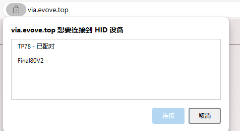
VIA Support:
Ultra-thin casing (extremely thin, without exposing the switches)

Chamfered gasket-like positioning plate
. Attachments:
final80v2.zip (QMK folder; to compile yourself, extract to the qmk folder (qmk_firmwarekeyboards) and compile (command: qmk flash -kb final80v2 -km via)); final80v2.json (VIA (evove.top) JSON file); casing model and hardware (available on MakerWorld, verified with an A1mini; welcome to print if you have a keyboard). Also, please give a thumbs up: Lao Xuan V2 Hot-swappable Keyboard VIA Version from Seriscyberalchemist - MakerWorld
final80v2.zip
final80v2.json
Positioning plate.dwg
PDF_Lao Xuan V2 Hot-swappable + VIA Version.zip
Altium_老璇V2 Hot-swappable + VIA version.zip
PADS_LaoxuanV2 Hot-swappable + VIA version.zip
BOM_老璇V2 Hot-swappable + VIA version.xlsx
94915
electronic
 input power board at 5V showed normal operation (a slight voltage error was due to the feedback resistor tolerance).
 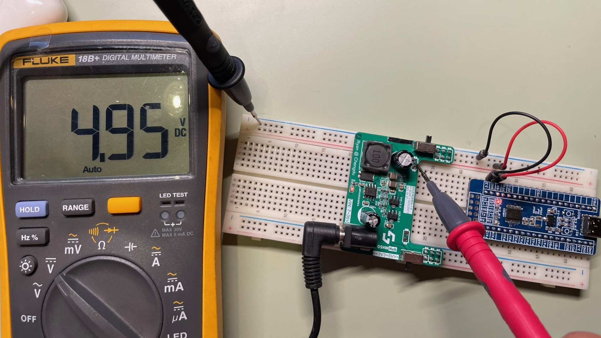 Switching to 3.3V via a switch also resulted in normal operation.


 京公网安备 11010802033920号

 50S-1268


