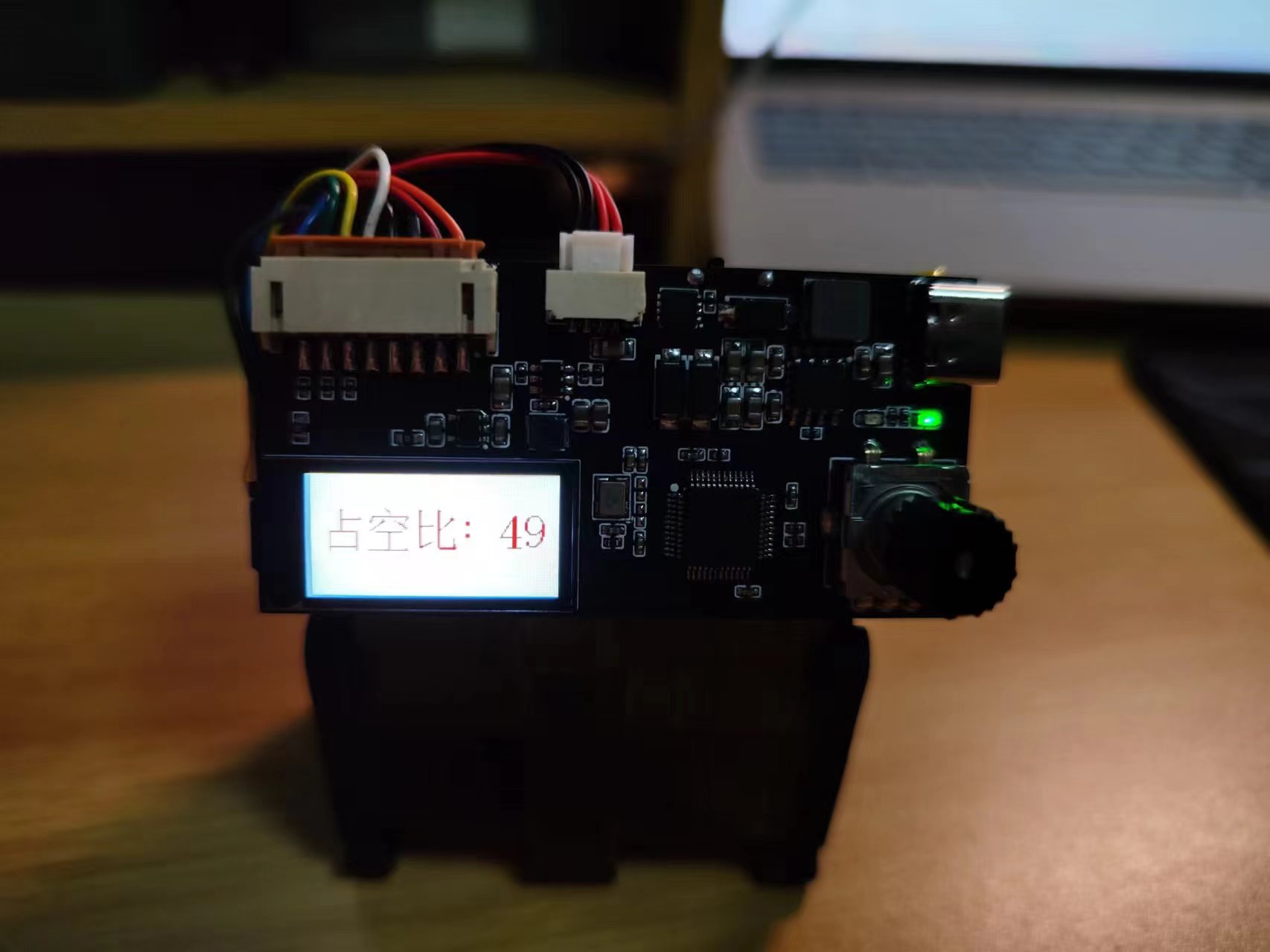
: 1. Infinitely adjustable duty cycle via an encoded switch;
2. Real-time duty cycle display on a 0.96-inch LCD screen
; 3. Supports 3-second battery charging and simultaneous charging and use;
4. Power on/off via a DIP switch.
The ESP32S3R8N8 is SMT-packaged onto an expansion board. The front panel minimizes traces, showcasing the colored silkscreen printing. The top left 4-pin connector is the screen; pin 48 is an indicator light; pins 39 are for the WS2812B BOOT and RST pins, which are not brought out. [Some people like the S3R8N8's appearance, some don't; to avoid it gathering dust, let's create an expansion board with a different color.]
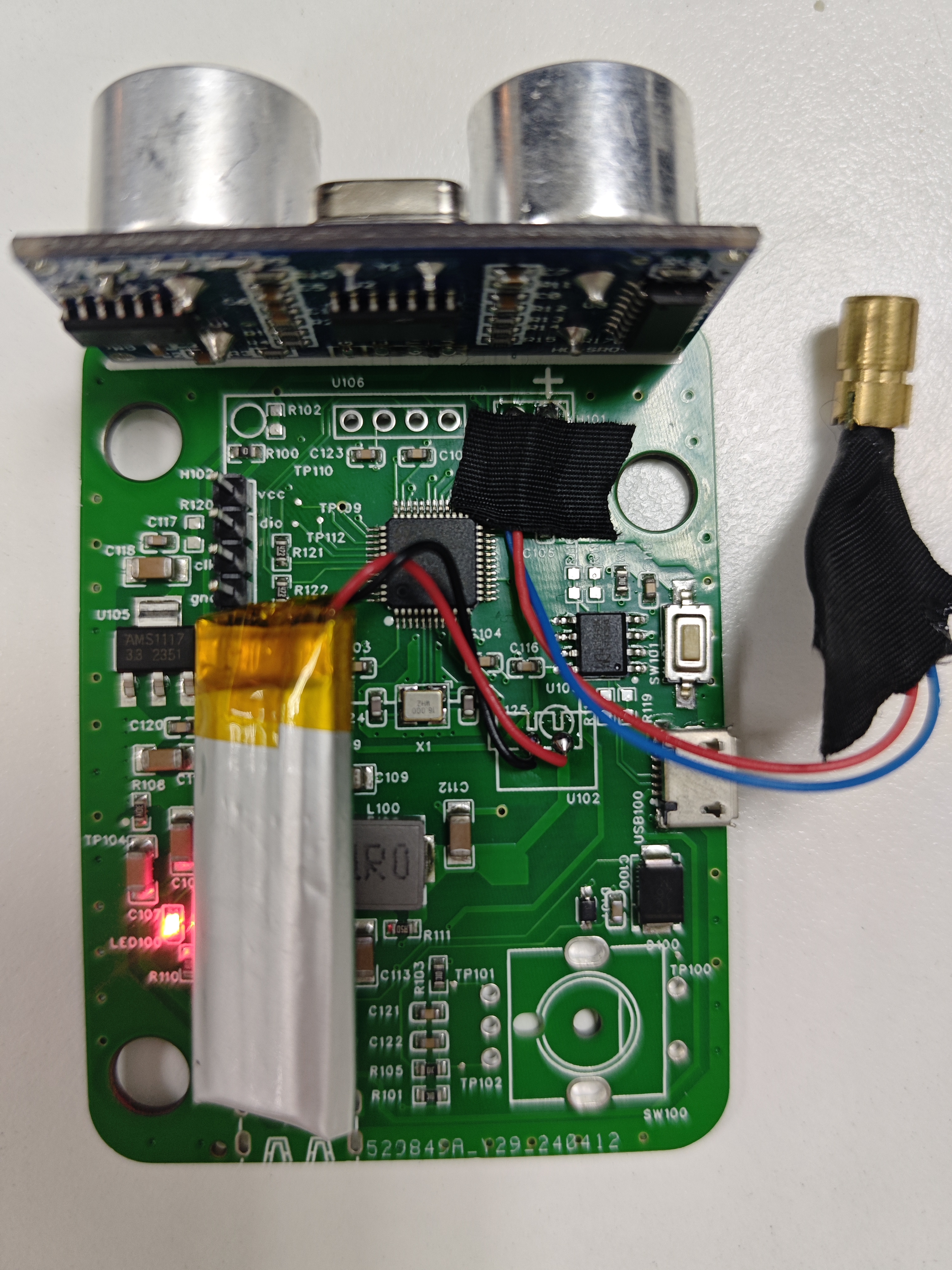
This is a handheld ranging device that includes ultrasonic sensors, an encoder, an OLED display, power management, and an STM32F103C8T6 microcontroller. This project is used to learn IIC, interrupts, input capture, and the encoder module is very user-friendly; the hardware is easily replicable, and the software engineering will be open-sourced.
I. Project Introduction
This is a handheld ranging device. The input modules are ultrasonic waves and a roller. The roller can move along a curve to provide feedback on the distance along the curve. The display module is an OLED, with an additional laser light to calibrate the position of the ultrasonic measurement. It has a built-in charging and discharging module, and the main controller is an STM32F103C8T6.

II. Project Related Modules
1. Ultrasonic distance measurement, range 2cm-400cm
2. Roller measuring curved distance
3. OLED display
4. Power management, charging and discharging module settings
5. Minimum system design of STM32F103 main controller
III. Application Scenarios
1. Distance measurement
2. Learning embedded hardware and software
IV. Project Completion
Schematic design 100%
complete PCB design 100%
complete Code design 90%
complete 3D shell design 100% complete
V. Soldering Demonstration
Soldering Notes:
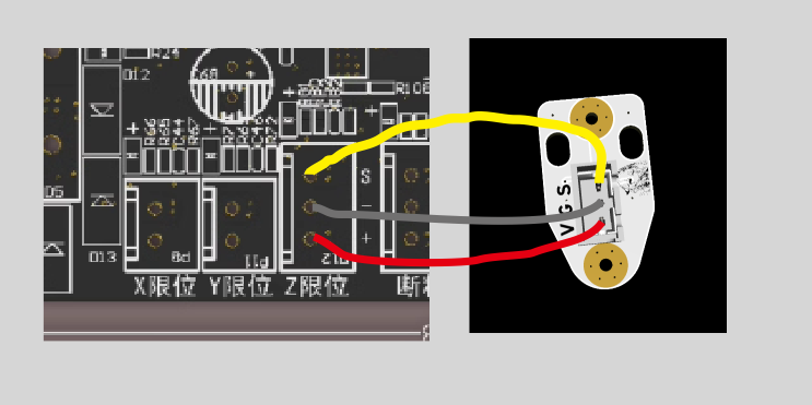
1. The OLED needs to be connected via a jumper wire and mounted to the shell.
2. The outer diameter of the laser light is 6mm. Voltage 3V or 5V is acceptable
. Battery pack dimensions: 50*12*35
mm. Notes:
1. Download the program using the SW interface, which requires J-Link. If you want to download via serial port, you need to modify the BOOT mode.
2. The encoder part of the program sometimes has errors; it may recognize forward rotation as reverse rotation. (I'm a beginner with programming, so the bugs haven't been fixed yet.)
Demo video:
[Radarmeter] https://www.bilibili.com/video/BV1QZ421n75C/?share_source=copy_web&vd_source=8f96cfa2f7d34667a143664dd03d7280
Thanks to the developer for the open source! This is a smaller version of the original H616 development board project based on Yuzuki Chameleon: https://oshwhub.com/gloomyghost/yuzukih616.
The Bomb Pi Zero
completely redesigns and relayouts the PCB to reduce its size and adapt to JLCPCB's through-hole technology.
To further reduce size, the eMMC is placed on the back.
The GPIO pin definitions are silkscreened on the back.
There is no copper around the screw holes, so there's no need to worry about soldering (the copper pillars won't connect to GND).
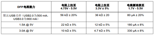
The CC pin resistor of the Type-C port has also been modified. The original circuit might have issues when using CC lines or cables with E-mark.
Other circuits remain unchanged and function identically. The initial version of

V1.0 could not be programmed for unknown reasons. Thank you, Ling.

Reference project addresses: https://euclidprobe.github.io/cheap
magnets 6x3 with 3mm countersunk holes (N25) (not recommended, you might find 3.6mm inner holes)
https://item.taobao.com/item.htm?_u=m2jk0vj06b22&id=677223530485&spm=a1z09.2.0.0.76042e8dFux8uT
better magnets 6x3 with 2mm countersunk holes (N35)
https://item.taobao.com/item.htm?_u=c2jk0vj07530&id=564130787836&spm=a1z09.2.0.0.2b762e8dpNwhr6
stronger magnets 6x3 with 2mm countersunk holes (N52)
https://item.taobao.com/item.htm?app=chrome&bxsign=scdI4jZwgweQJxe7DKUhjPhlSGEgq80cXj_ry7_K4EmcqG7KSOfez4wRH6t5lfJz4jHQqNMzqastVM0M--OIteZFcqz7IZYnzUR0yj0jJ_dDRtfPkHlMJReSCXTXvpleI jB&cpp=1&id=692502462669&price=0.45-205&shareUniqueId=26392620501&share_crt_v=1&shareurl=t rue&short_name=h.gbXn1d0qaovUOWg&skuId=5275772107137&sourceType=item,item&sp_tk=TW9aRFdJdk ZtQVc=&spm=a2159r.13376460.0.0&suid=2789ab31-2122-4e9b-bb3c-04a9956f3d8b&tbSocialPopKey=sh areItem&tk=MoZDWIvFmAW&un=09603feadf49d3dcb2f10b56166a698d&un_site=0&ut_sk=1.YvxmZCNpDp0DA I6w6OL4SdMC_21646297_1713960094240.Copy.1https://item.taobao.com/item.htm?id=745674021802&skuId=5465764879434&spm=a1z0d.6639537/tb.1997196601.270.296774841W2NCW
Recommended by a pro: supposedly high-precision 6x3 hole 2mm magnet. Countersunk (N52)
https://item.taobao.com/item.htm?id=745674021802&skuId=5465764879434&spm=a1z0d.6639537/tb.1997196601.270.296774841W2NCW
Small head screw M2X4 3mm head (not suitable for cheap magnets)
https://detail.tmall.com/item.htm?_u=c2jk0vj0c3d0&id=717467816792&spm=a1z09.2.0.0.2b762e8dpNwhr6
Countersunk head screw M2x4 3.5mm head (suitable for cheap magnets) (If your magnet has a 3.6mm inner hole, this screw will not work)
https://detail.tmall.com/item.htm?abbucket=18&id=640310583202&rn=f9d09ca2fc4d245e32db9cb892f4f1bb&skuId=5518857014336&spm=a1z10.3-b.w4011-22615119255.94.1239f5e5sapn93
TTC micro switches
: https://item.taobao.com/item.htm?_u=c2jk0vj0710f&id=705433676474&skuId=5270176938209&spm=a1z09.2.0.0.2b762e8dpNwhr6
Omron micro switches
: https://item.taobao.com/item.htm?id=574796579888&spm=a1z0d.6639537/tb2.1997196601.183.483e7484YZPJ9s
SMTSO-M2-0.5ET surface mount nuts for version 6.3 The link provided
(https://item.taobao.com/item.htm?spm=a1z0d.6639537/tb2.1997196601.3.bc637484UYbuhc&id=636483838062
) lists 0603 surface mount resistors. (For 5V standard brightness, choose 0.51K; for 5V high brightness, choose 0.33K; for 24V high brightness, choose 2.4K; for 24V standard brightness, choose 4.7K).
The LEDs used are 0805 surface mount LEDs. A soldering station is available to mount 1206 LEDs. The dual-color white LED uses 1206 (brighter!).
A dual-color version has been added (one LED is always on, and the other is mounted on the lower PCB and lights up, turning off when triggered).
Because of feedback regarding mounting hole placement errors, version V5.4 changed the mounting holes to oblong holes.
A good design was seen on Douyin, so version V5.5 changed the connector pads to XH2.54/PH2.0 universal pads (two pads stacked together).
A new version 6.2 with a step-down circuit has been added. This product
uses an SOT23 packaged LDO voltage regulator chip,
with a jumper added to switch between always-on and triggered LED operation.
A Schottky diode is added for protection (this may cause MCUs with an I/O voltage of 3.3V to malfunction).
For PCB testing
of the voltage regulator chip, please refer to: https://item.taobao.com/item.htm?_u=i2jk0vj0854b&id=643357241091&spm=a1z09.2.0.0.6e582e8dCA7CCG.
Version 6.3 removed the never-used Zener transistor
thread and uses a surface-mount nut.
Version V7.xx
added a version without the "soul" (LED), making it simpler to build.
Please indicate the open-source address or the group number below when selling
. After all, I only created this to increase the number of group members.
Group: 701827620

Version 5.5 3D model.step
klicky V6.2 BOM table.xlsx
klicky adjustable stand.zip
PDF_klicky 3D printer magnetic probe.zip
Altium_klicky 3D printer magnetic probe.zip
PADS_klicky 3D printer magnetic probe.zip
BOM_klicky 3D printer magnetic probe.xlsx
94985
Lower layer Arduino surface mount
The power supply PCB board can output 12V and 5V, with a maximum current of 2A for the 5V output. It can be made to be mounted on a microcontroller; currently, it's used for Arduino surface mount technology.
The power supply PCB board can output 12V and 5V, with a maximum current of 1A for 5V. It can be made to be mounted on a microcontroller; currently, it's used for Arduino surface mount technology.
PDF_Lower Layer Arduino Patch.zip
Altium_lower-layer Arduino patch.zip
PADS_Lower Layer Arduino Patch.zip
BOM_Lower Layer Arduino Surface Mount.xlsx
94986
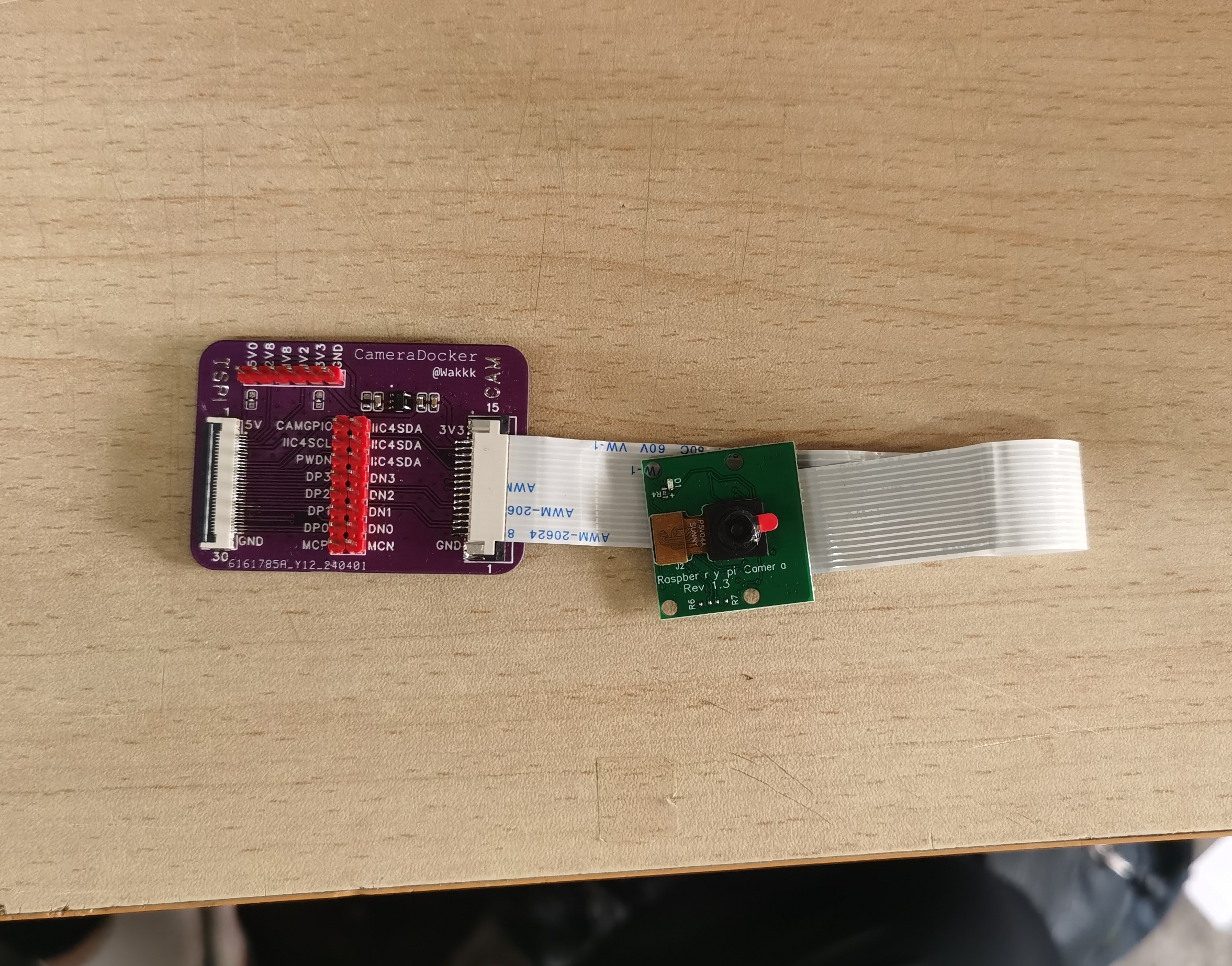
Taishanpai CSI Raspberry Pi Camera Adapter Board
Raspberry Pi camera 0V5647 and Taishanpai CSI interface adapter board
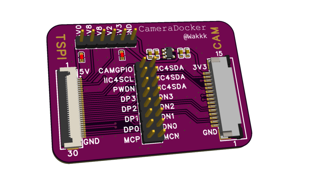
The other power supplies for the Taishanpai CSI interface are brought out for debugging purposes.
All data lines are brought out for debugging
from the 5V system power supply to output 3V3.
PDF_Taishanpai CSI Raspberry Pi Camera Adapter Board.zip
Altium_Taishanpai CSI Raspberry Pi Camera Adapter Board.zip
PADS_Taishanpai CSI Raspberry Pi Camera Adapter Board.zip
BOM_Taishanpai CSI Raspberry Pi Camera Adapter Board.xlsx
94987
electronic


 京公网安备 11010802033920号

 K4S56323PF


