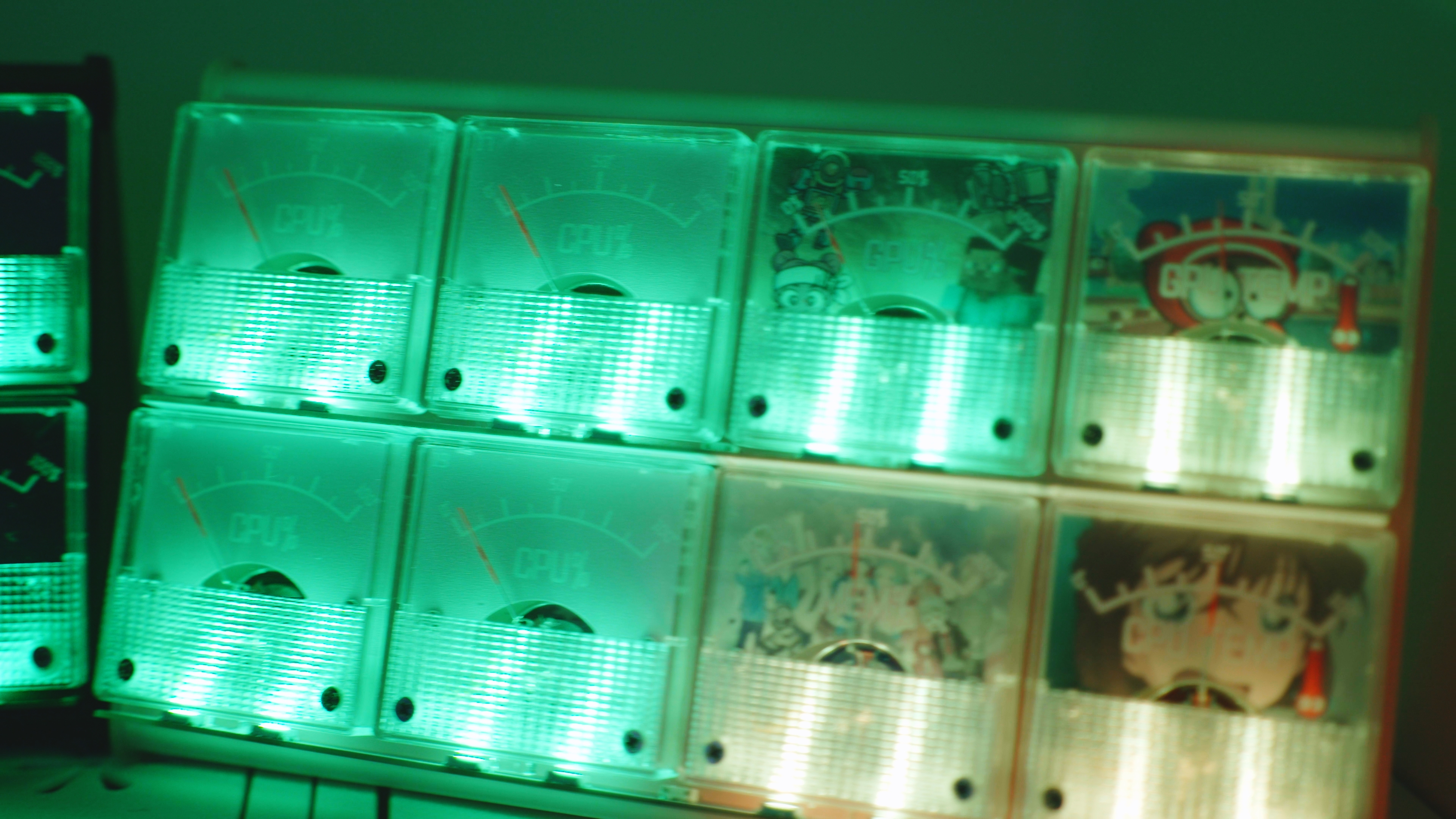
The worn-out price tag screen, along with the ten AIR001s I bought before, actually look quite nice with the case on.
This uses a dual-mode numeric keypad from the ESP32S3, featuring a rotary encoder and a replaceable screen;
unused I/O is brought out for expansion, allowing for the addition of touch buttons, joysticks, and other modules;
keyboard routines from the official library and the Blekeyboard library have been modified to support full-key rollover.
Using the ESP32S3-Wroom-1 module, I implemented a Bluetooth-wired dual-mode keyboard. It supports full N-key rollover but only up to 6 keys can be pressed simultaneously (due to keyboard library limitations, which I don't know how to modify). After some research, I figured it out. The official library is well-encapsulated; you only need to modify the report descriptor.
It supports media keys, and the key bindings can be changed in the source code.
It features a partially modular design, allowing you to choose between the screen or two additional buttons, and expose unused pins for expanded functionality.
It can be battery-powered, automatically switching when plugged in, but low power consumption isn't implemented, so prolonged Bluetooth connection is not recommended. I added a deep sleep mode, but reconnection is slow—that's unavoidable.
Random thoughts: I referenced designs from various experts. Originally, I planned to use a HoloMatic C3 module + CH422 + CH9329, but after calculating the cost and considering HoloMatic's price increase and the hassle of coding, I decided to design my own development board and redesign it using the S3 module. HeZhou, you've changed!
Update:
24.11.15 Update:
I found a bug in the files from the last update. I directly modified the files in the official repository, which weren't in the project files.
The problem was with the usbmsc function. The constructor of the official USBMSC class adds an MSC interface to USB. So I deleted the content in the parameterless constructor and added a parameterized constructor to prevent adding the MSC interface when declaring the class object. This way, an inaccessible disk won't be generated when using the USB keyboard.
Solution 1: Use the latest project files;
Solution 2: Modify the corresponding files yourself as I mentioned above;
Solution 3: If you don't care about clutter when using USB mode, just delete the use_msc parameter in the error-causing USBMSC(use_msc);
I deleted the old project files, only keeping esp32s3_NKRO_keyboard.zip;
the latest project file is esp32s3_kb_v1_N8R2.rar.
24.11.11 Update:
Added USB MSC mode, when enabled, simulates the FAT partition as a USB drive for reading external configurations, etc.;
adds an Fn key toggle function, allowing switching between the original layer and the Fn layer keys;
adds screen functionality using LVGL:
displays the current connection status (Bluetooth, USB), and whether the default layer is the Fn layer or the original layer;
displays built-in images and allows rotation;
can switch between displaying external images placed on the FAT partition using MSC mode;
external images are placed in the .lvgl_data folder on the disk in MSC mode and need to be renamed to 1.png ;
adds the function of reading external configurations:
saves external configurations in JSON format, allowing configuration of key bindings, keyboard names, sleep time, etc.;
includes a key binding setting tool in Excel spreadsheet, which needs to be updated. Open the Excel file; (it needs to support VSTACK formulas, the specific version update is uncertain).
The spreadsheet is in the keyboard tools/tools folder of the latest file;
external configurations are placed in the .configs folder of the disk in MSC mode, renamed to userConfig.json;
if you need to manually write the configuration, you can refer to the defaultconfig file in the same directory;
some keyboard and encoder scanning related functions have been modified;
the latest file is esp32s3_kb_v1_N8R2.rar.
If it is an N16R8 module, you need to replace the platformio.ini file with the N16R8 version, which is already placed in the project directory, just rename and replace it.
Functionality:
Implemented features:
Wired and Bluetooth dual-mode (tested only on Windows 11);
The ESP32S3's USB port also has a serial download function. A capacitor at the boot button may cause the boot pin to power on late. If the upper left corner light doesn't flash, it may be in download mode; a power cycle will resolve this
. Switching from wired to Bluetooth does not automatically reconnect; therefore, an automatic restart is used each time the mode is switched (but note that this soft restart will increase power consumption when switching from Bluetooth to USB mode);
The keyboard supports true full-key rollover, and also supports media keys (partial support in Bluetooth mode), up to 6 key combinations at once, and 2 Fn layers;
Key values can be edited by modifying the source code;
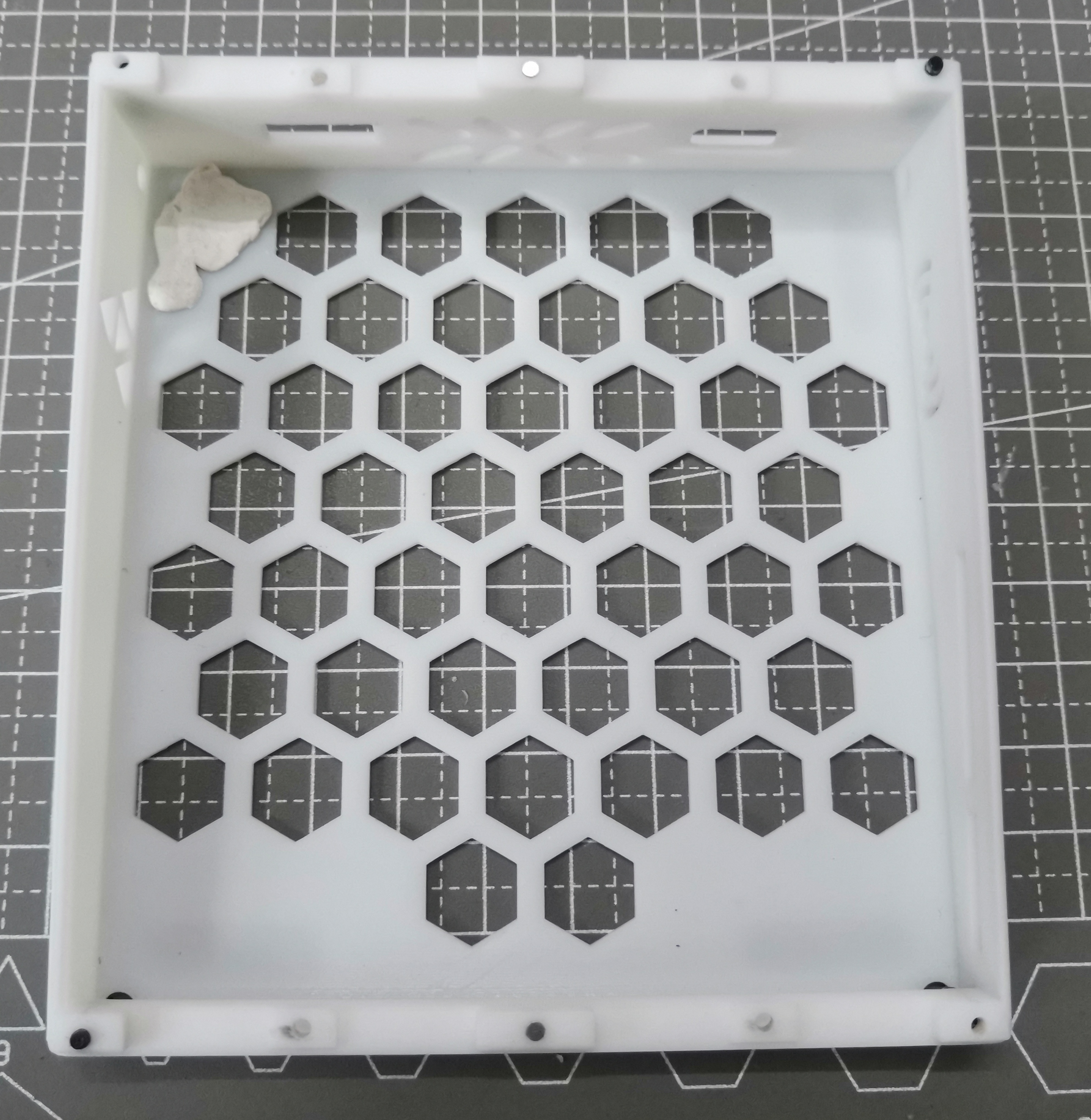
There are a maximum of 19+1+2 keys: 19 mechanical switches in the keyboard matrix, 1 rotary encoder switch in the keyboard matrix, 2 independently controlled mechanical switches, and a screen selector.
The WS2812 features a RGB backlight, one for each mechanical axis, totaling 21 pins. Only the on/off functionality is implemented; the driver library has multiple preset lighting modes that can be modified via the source code.
It's merely a screen that lights up, sharing pins with two additional buttons. Pressing the shortcut key and then powering off and restarting switches the mode.
The code is terrible and getting worse.
A feature implemented but not verified after errors was redone:
RGB brightness is controlled via PWM on the pins. Capacitors were initially forgotten, and even with them, it might not work.
The WS2812 can control its own brightness, possibly by scaling RGB values proportionally. I'm trying PWM control; if that doesn't work, it will only be usable as a regular switch.
Expandable modules (
though this is currently unavailable): 4 touch pins + 2 ADC pins. The pins themselves have essentially the same function, but the ADC pins have reserved capacitors near the module. Using one touch pin as an ADC might affect wireless functionality.
Next to the ADC pins is a regular GPIO that can be combined to create a switch/joystick.
There are also 5 additional keyboard matrix keys, in the 5th column of the keyboard matrix.
It has one pair of serial ports and one pair of I2C pins for connecting to other chips. The I2C pins also have touch and ADC functions. There are
three startup-related pins, which are brought out for backup and can be used as GPIO after startup.
Installation Notes:
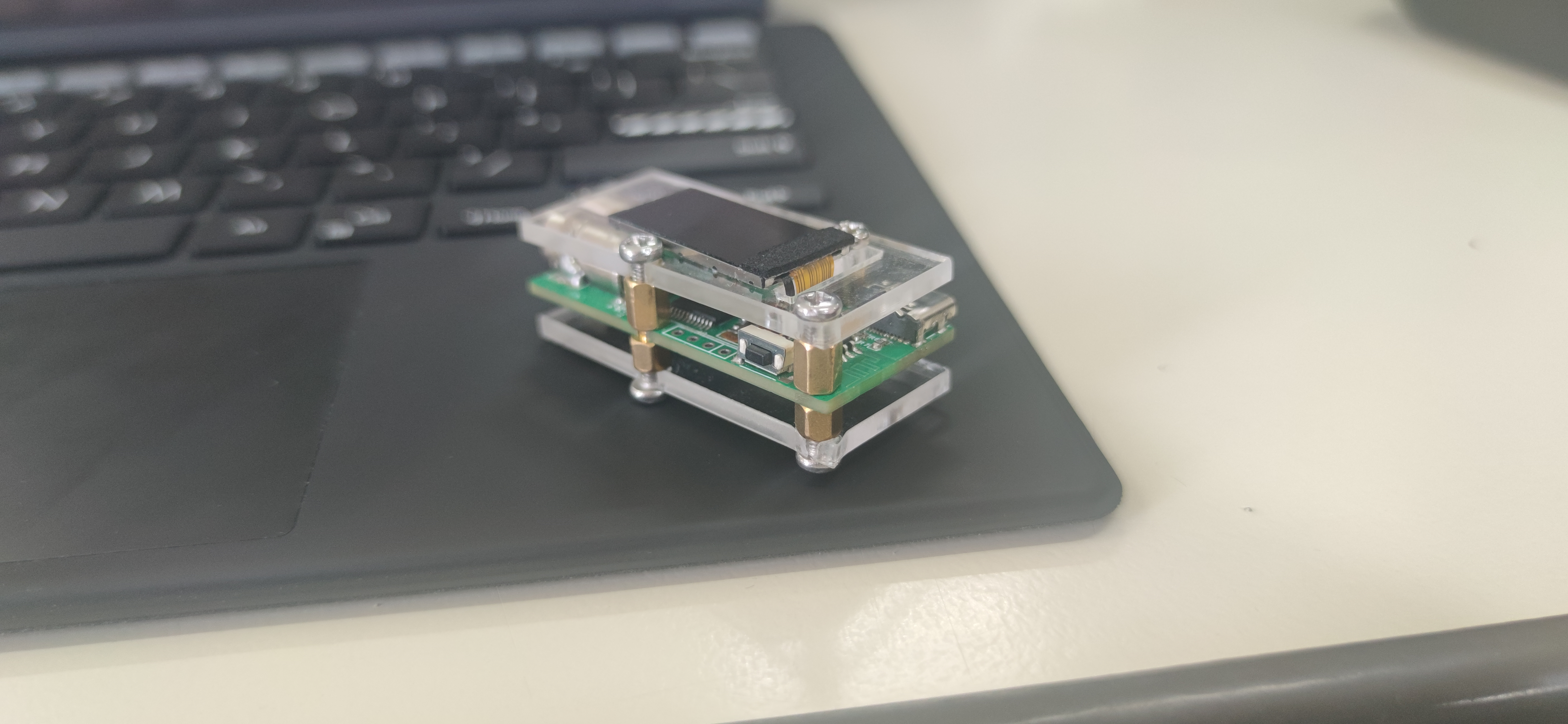
Driver Board: Powered by SY8088 DC power chip, TP4056X for battery charging, 40-pin 0.5mm pitch for FPC female connector pins;
The capacitor below the boot button is optional. Installing it may require two boots to enter the normal program, as the boot level is low before the capacitor charges, which will enter download mode. 100nF is too large in practice; The
5.1kΩ resistor below the C port is related to the power supply protocol. We only need 5V power, so it's not actually necessary; (What was I writing before?) The 5.1kΩ resistor is for CTOC charging to be recognized, and it's not recommended to omit it; The
anti-static diode is too small; you can omit it if you find it difficult to install;
The values of the MOSFET and other similar pull-up/pull-down resistors, LED voltage divider resistors can be selected as needed, as long as the function is achieved;
The 5V pin on the upper left is only for input, and there is a diode connected to it (the left side is ground);
The 0Ω resistor can be replaced with wires on a different circuit board, reducing the number of resistors;
ESP32S3 module selection notes:
It is recommended to choose modules with PSRAM of 2MB or less. For modules with 8MB or more, I/O pins 33-37 cannot be used, and pins 33-34 are not brought out in any module.
For modules without PSRAM, pulling I/O45 high during power-up will cause the flash voltage to be 1.8V. It is recommended to choose modules with PSRAM to eliminate this concern.
The 499Ω resistor recommended for serial port is already connected in series in the module and does not need to be installed separately. The power supply voltage
of the SY8088 DC power chip
is determined by the two feedback resistors. It is recommended to use at least 100kΩ for the smaller one and 4.5 times that for the larger one. A small capacitor can be connected across the larger one to enhance dynamic response.
The chip enable pin needs to be connected to a 5V input and kept high to supply power. The keyboard controls the switch through this pin. However, if the keyboard matrix board is not connected, the pin shown in the diagram needs to be shorted to start the chip because of the capacitor. To stop the chip, the EN pin needs to be grounded. You can find a nearby ground to short it.
The charging current of the TP4056 is determined by the resistor shown in the diagram; if I remember correctly, the current is 1000Ω/resistance.
The keyboard matrix uses WS2812B LEDs in a 6028 package and an EC11 encoder. The PCB connects to the driver board via three 8mm double-through studs.
The capacitors connecting the matrix input pins are unnecessary; debouncing will be handled in software anyway, so physical debouncing is unnecessary. If you really want to add it, add a smaller one.
The 10kΩ resistor near the keys is an input pull-up resistor, and the 1kΩ resistor is an output pull-down resistor. The intention is to trigger an interrupt in sleep mode, so there's no need to set up additional pin outputs before sleep mode (although I didn't actually write any sleep mode code).
The RGB voltage divider resistors can be directly shorted. The brightness of the WS2812 can be controlled via software.
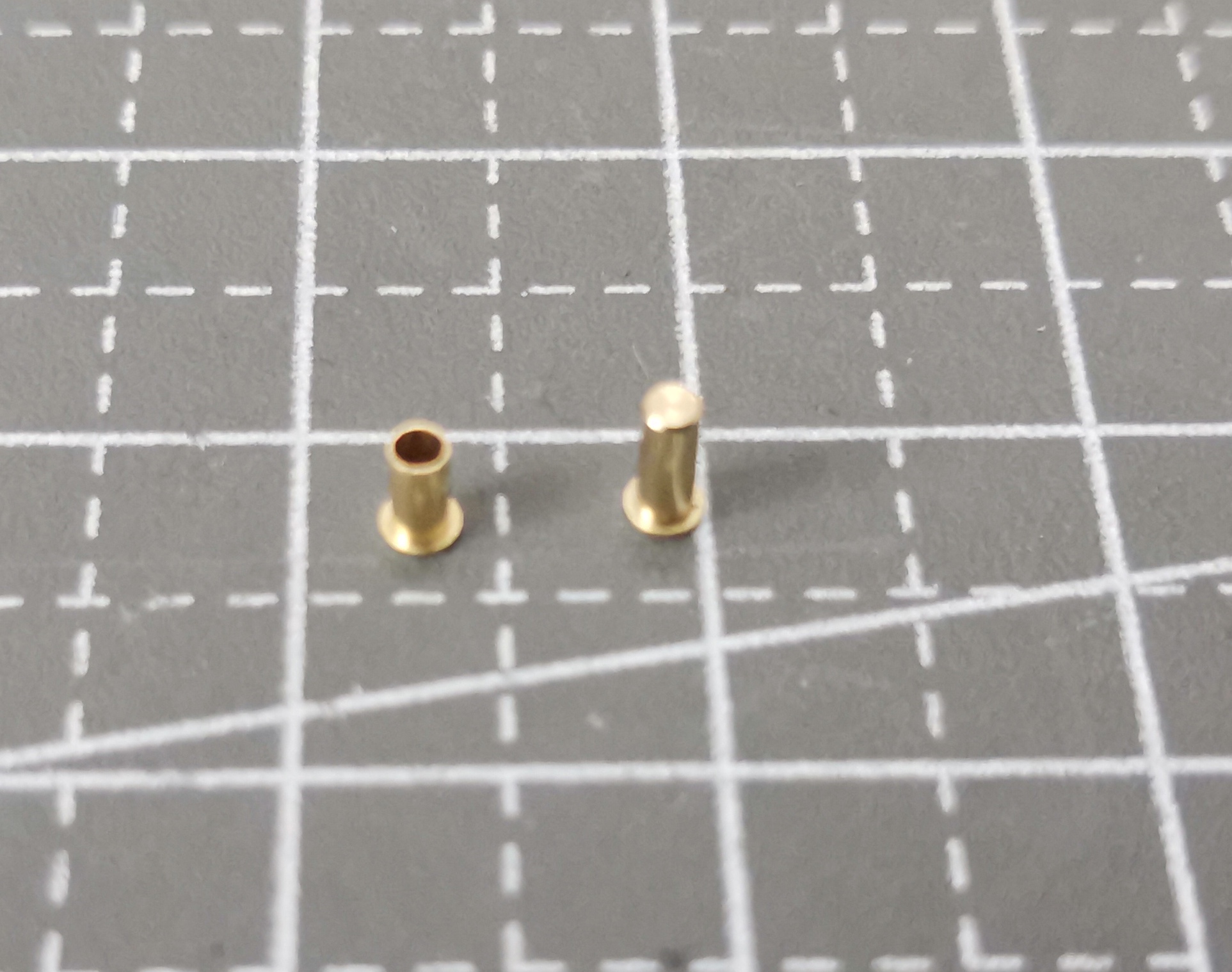
The two additional key switches use copper eyelets with claw springs; it's recommended to choose enclosed ones, as they are honestly a bit expensive. Otherwise, replacing all the switch holders with these would save a lot of space. Keyword: hot-swappable sleeve.
The encoder's five signal pins can also use this type of connector for easy disassembly, but it will wobble slightly. The ribbon cable in the diagram for
the positioning plate and battery
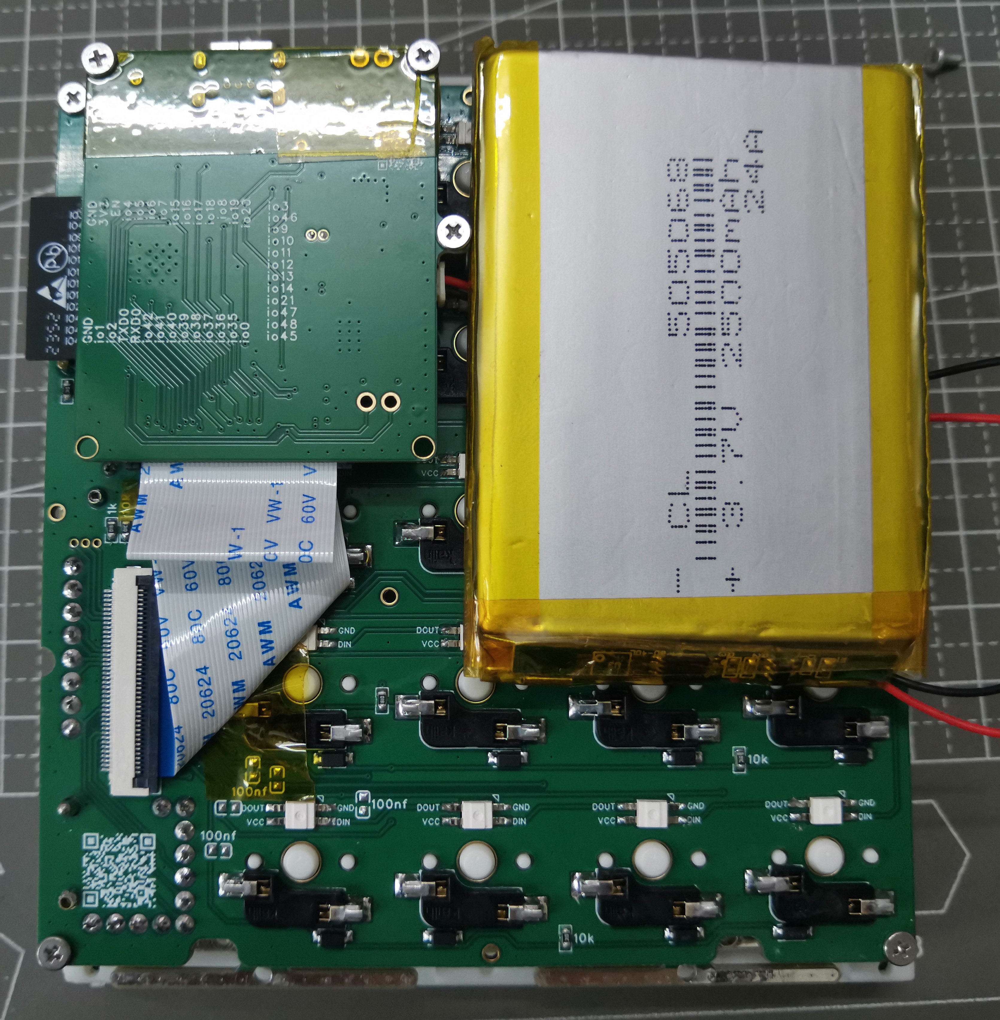
is 5mm and needs to be folded.
When the battery is placed as shown, its width is at most about 50mm; placing it horizontally at the bottom allows for greater width, but the maximum length is smaller.
The keyboard matrix and positioning plate are connected via 3.5mm studs. M2 double-through studs are available on the market, with two mounting holes at the four corners and two on the beveled side. The longest screw is 3+4mm.
There is also an M1.6 welded copper stud with a length of 3.5mm, with two welding holes at the midpoint of the four sides and two on the beveled side. The holes
in the rest of
the casing are all 1.9mm in diameter. I originally wanted to install 2.5mm knurled nuts, but after trying, the casing skipped the melting process. Since it's carbonized directly, just use M2 screws. There are clips between the cover and the bottom; if you don't mind a loose fit, you can skip the screws. For the screws between the cover and the bottom, a length of 6-8mm is recommended.
The bottom shell comes in both perforated and non-perforated versions; using 3D Monkey X resin can save you 2 yuan.
Use Blu-Tack to attach the battery for easy removal.
There are 1mm diameter, 1mm high holes in the middle of the top and bottom edges; you can install magnets, but it's difficult and not very useful.
The positioning plate is a poor imitation of the gasket structure; theoretically, you can use rubber pads to fix the four ears, but the C-port opening position needs to be calculated carefully. Use M2 screws, 4mm long.
The switch cap is A28 height, basically flush with the top of the cover.
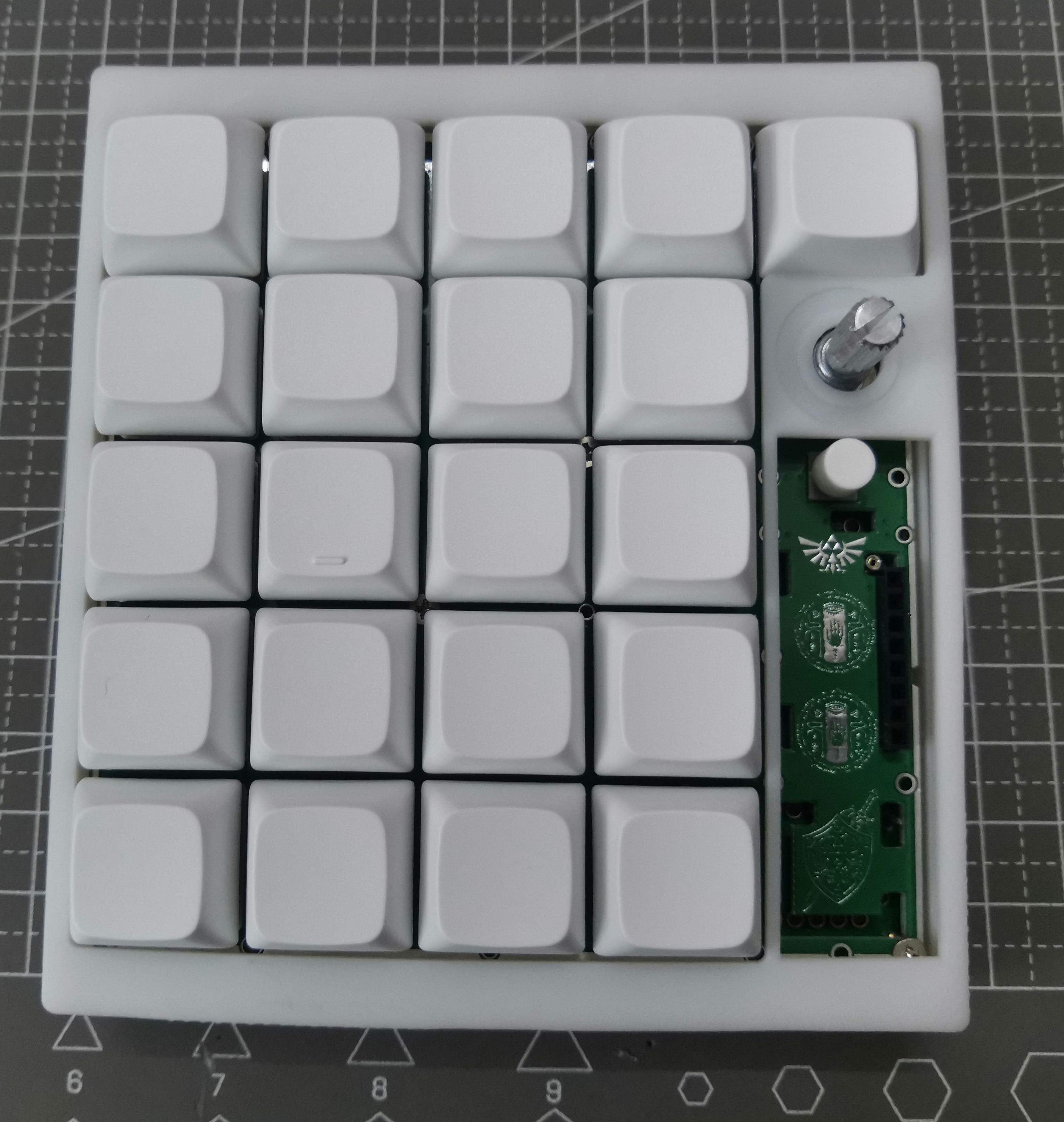

The encoder is basically centered relative to the buttons; the button spacing is 19.05mm, so an encoder cap diameter of 19mm or less is fine, but you need to consider the tolerance of the encoder shank not being straight.
The screen module

/screen shell is quite difficult to install; I suggest not installing it for personal use (since the software function isn't implemented anyway).
The screen shell is clipped to the positioning plate; you might need to remove the screen when doing so. The bottom edge of the shell needs to be pushed inwards to pull it out;
the screen module pins can be connected using 2.54mm long headers or short headers combined with header nuts;
the header length needs to be adjusted with pliers;
when using header nuts + headers, first insert the two 4-pin header nuts onto the switch housings, then insert the screen headers, which is easier to align than long headers, but requires cutting off part of the clips, as shown in the white shell in the picture above;
some
small components on the keyboard were mounted using a heat plate, while the switch housings and RGB components were hand-soldered because I was unsure of their heat resistance. I will also release the heat plate file I used, but previously a certain supplier could mount aluminum substrates with copper thickness exceeding 10cm and 1oz, but last time I saw it was only 0.5oz, so if you want to get it for free, you may have to draw it yourself;
the positioning plate was also sourced from a supplier, but for thicknesses exceeding 10cm, only 4-layer boards can be selected, and the slotting is not very precise, so it may need to be mounted twice;
after installation, I found some problems, and I slightly modified the PCB. The latest one is not exactly the same as the one in my picture, but these are minor modifications and should not affect the actual effect. The biggest problem is the positioning plate. The slot in the lower right corner of the keyboard panel was originally too short, requiring manual grinding to shorten it before installing the header nuts. This has now been corrected.
There was a definition conflict between the Bluetooth and USB keyboard libraries, so I modified some code in the libraries. If you install the libraries yourself, this conflict is normal; you just need to manually modify it. The code I provided is from Platform.io, and the entire folder is quite large, so only a portion is shown. You might need to create a new project first, import my ini file, and then overwrite my code.
I modified the HID report descriptors of the two keyboard libraries to support full-key rollover, storing 136 different keys in 17 bytes. Theoretically, this allows simultaneous pressing, but I'm too lazy to modify the key and ASCII mapping algorithms defined in the official libraries. Currently, it only supports 128 keys pressed simultaneously.
Because the implementation of full-key rollover is definitely different from a standard keyboard (boot keyboard), it's uncertain whether some very old devices will support it in boot mode.
The key configuration methods are all in the source code, so I won't go into detail here.
Because it lacks a physical battery switch like a normal keyboard, even when wired, the keyboard will still be powered by the battery after the computer is turned off. Currently, it's set to enter deep sleep after 20 minutes of inactivity in Bluetooth mode, and three times that time in USB mode.
When entering deep sleep, the USB connection to the computer disconnects (it makes a "ding" sound), and there's a delay of at least 500ms after waking up, preventing timely message transmission. I didn't bother with an instant wake-up response.
I did implement a function to read the key presses at the moment of wake-up, but the time from deep sleep to startup is at least 300ms, and then almost 1 second to USB connection to the computer, making it inappropriate to pretend a key was pressed during that time.
Because the encoder input pin is pull-up, while other inputs are pull-down, I didn't implement an encoder knob for waking up from deep sleep.
Regarding power consumption
, I measured the entire keyboard current with a multimeter without a battery connected, for reference only:
Mode
current:
Power switch off
(battery chip not connected but still enabled, DC chip not enabled):
0.3mA
deep sleep mode
: 1.3mA
chip clock frequency 40MHz (GB display is incorrect);
30mA
chip clock frequency 80MHz.
40mA
chip clock frequency 120MHz;
60mA
chip clock frequency 240MHz;
64mA
240MHz + Bluetooth
120+mA
pink light, brightness 20;
20mA
pink light, brightness 255 (max);
130mA
abnormal mode: after switching from Bluetooth to USB
(only software restart, no power switch reset);
80+mA
, it is recommended to use a clock frequency of 240MHz, don't turn the light too bright, manually restart each time you switch modes, as software restarts may not reset some peripherals;
## The latest code consists of two files: esp32s3_NKRO_keyboard and esp32s3_NKRO_keyboard_with_lib. The former runs platformio's deep clean and does not install libraries, but will automatically download them after opening; the latter includes the libraries.
I will not upload minor code changes to the attachments. You can check them on GitHub:
https://github.com/gdnre/ESP32_NKRO_KeyBoard
. Construction is complete.
If anyone wants the BOM (Bill of Materials), please leave a comment. If no one needs it, I'm too lazy to compile it; a quick check shows that the automatically generated BOM is usable.
PDF_ESP32S3-Bluetooth Wired Dual-Mode Hot-Swappable Keyboard-Full Keyboard Anti-Ghosting.zip
Altium_ESP32S3-Bluetooth Wired Dual-Mode Hot-Swappable Keyboard-Full Keyboard Anti-Ghosting.zip
PADS_ESP32S3-Bluetooth Wired Dual-Mode Hot-Swappable Keyboard-Full Keyboard Anti-Ghosting.zip
BOM_ESP32S3-Bluetooth Wired Dual-Mode Hot-Swappable Keyboard-Full Keyboard Anti-Ghosting.xlsx
2024 LCSC Training Camp [Beginner Zone]: A simple digital oscilloscope replica based on the GD32E230C8T6, following LCSC's official instructions. It has simple functions and is intended for beginners only, serving as a foundation for advanced learning. A richly annotated version of the code is attached.
Foreword:
April 25, 2024. New 3D shell files have been updated in the attachment.
I. Introduction:
Thank you JLCPCB for providing this opportunity for beginners to learn about electronics!
Thank you JLCPCB for the detailed tutorials and documentation!
Thank you JLCPCB for the ¥20 3D coupon, ¥50 consumables coupon, and ¥30 3D coupon!
This open-source project description includes:
【I. Introduction】
【II. Project Description (Components, Functions, References)】
【III. My Understanding and Precautions】
【IV. Replication Suggestions and Problem Solving】
【V. Code Analysis】
【VI. Improvement Directions (Compiled by a beginner, please refrain from criticism by experts)】
【VII. Attachment Directory】
【Design Drawings (Schematic Diagram and PCB Diagram)】
【Attachments】 (Attachments include the original source code project, my richly annotated code, code study notes, 3D files, schematic diagrams, demonstration videos (with and without casing)...)
II. Project Description:
【Note: As a beginner, the hardware and software parts of this project are almost completely replicated from the official LCSC project.】
1. Main Components:
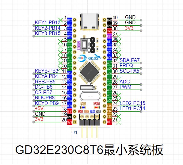
GD32E230C8T6 minimum system board, baseboard, and 1.8-inch TFT color screen. See the BOM below for other components.
2. Final Function:
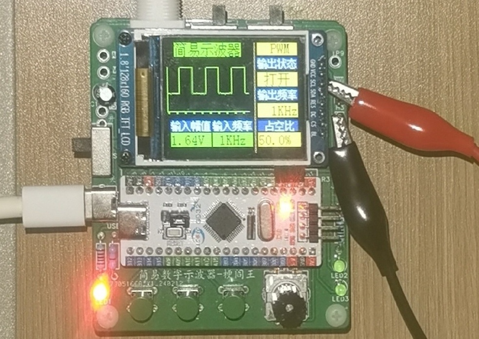
Can be used to measure the waveform, voltage, and frequency of simple signals.
2-1. Screen waveform and parameter display function
(1) Screen display waveform [Note that the waveform is displayed in reverse phase]
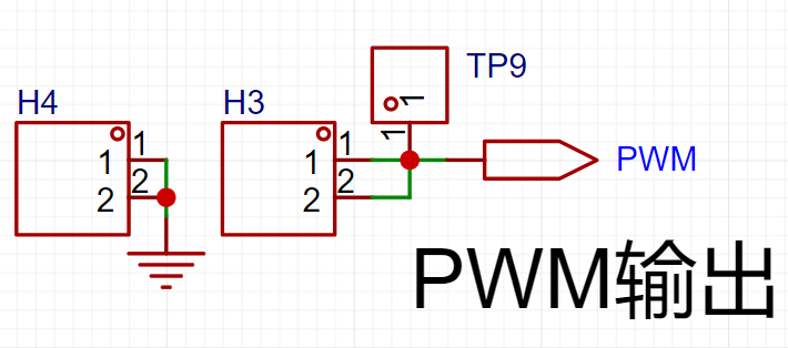
(2) Output signal parameter display (specifically PWM square wave)
Output status [Off/On]
Output frequency [1kHz, 2kHz, 4kHz]
Duty cycle
(3) Input signal parameter display
Input amplitude [Range: -1.6V~5V] (Because it is best not to use 1/50 attenuation in practice)
Input frequency [Theoretical measurable range: 1kHz~10kHz]
2-2. Human-computer interaction: Adjust waveform display and parameter function
(1) [Button KEY1] (left button)
Each press increases the square wave duty cycle in 5% steps, and it returns to 0% when it reaches 100%.
(2) [Button KEY2] (middle button)
controls the output and stop of the PWM square wave. Press once to turn it on, press again to turn it off.
(3) [Button KEY3] (right button)
switches the output frequency of the PWM square wave. Pressing it will cycle through 1Hz, 2Hz, and 4Hz.
(4) [Encoder] (lower right corner)
Pressing it will fix the waveform;
rotating the encoder clockwise will widen the waveform;
rotating the encoder counterclockwise will narrow the waveform.
3. Other
power supply: 5V DC
power supply interface: type-c
probe type: BNC to alligator clip
4. Reference materials (JLCEC official) (very important):
(1) Detailed open source documentation: (The "open source documentation" mentioned later refers to this)
https://www.yuque.com/wldz/jlceda/dso
(2) Free recorded courses on Bilibili:
Search for UP master: LCEC EDA, and view a series of videos from early 2004. This complements the open source documentation tutorial.
(3) Official reference code (code for each part, and the final code)
https://gitee.com/chen11232/GD32E230-Oscilloscope
[The attachment contains the original official final code project, as well as a version of the code project that I have added many comments to, which can be downloaded directly]
I suggest that beginners like me watch the open source documentation and the Bilibili recorded course together, because the official open source documentation includes [hardware design] and [software development], covering circuit principle analysis, schematic and PCB design, soldering tutorials and step-by-step code construction (I also learned GD32 by the way), which is very detailed.
Therefore, please refer to the official materials for details about this project. The following is not a copy of the official explanation (no matter how well I explain it, it is not as good as the official explanation), but my own understanding as a supplement. For some key points, details encountered and some tips during the replication process, please refer to "My Understanding and Precautions" below.
III. My Understanding and Precautions
[Part 1] Circuit Understanding and Schematic Drawing
(1) I drew almost completely according to the official schematic. All component reference numbers and pin selections and circuit connection methods are the same as the official ones. But at that time I did not know that LCSC EDA could adjust the shape of the schematic library of components such as display screens and test points in the schematic diagram (modification method: schematic diagram -> right-click on the component -> edit the device -> modify the library file), so it was just that the schematic layout was different from the official schematic diagram.
(2) When modifying, if you want to change the library containing two op-amp chips from a rectangle representing the chip to two triangles representing the op-amps, please refer to the official Bilibili video (BV number: BV1jy421i7Ji) (around 16 minutes and 27 seconds)
(3) After modifying the library, the new library is saved in "engineering library" instead of "system library"
(4) If you want to find the component description, you can click Place -> Component -> Enter number -> View PDF description in LCSC Professional Edition
(5) The automatic labeling steps can be viewed (BV number: BV1jy421i7Ji) (around 1 hour, 15 minutes and 31 seconds)
1. Analog front-end processing circuit
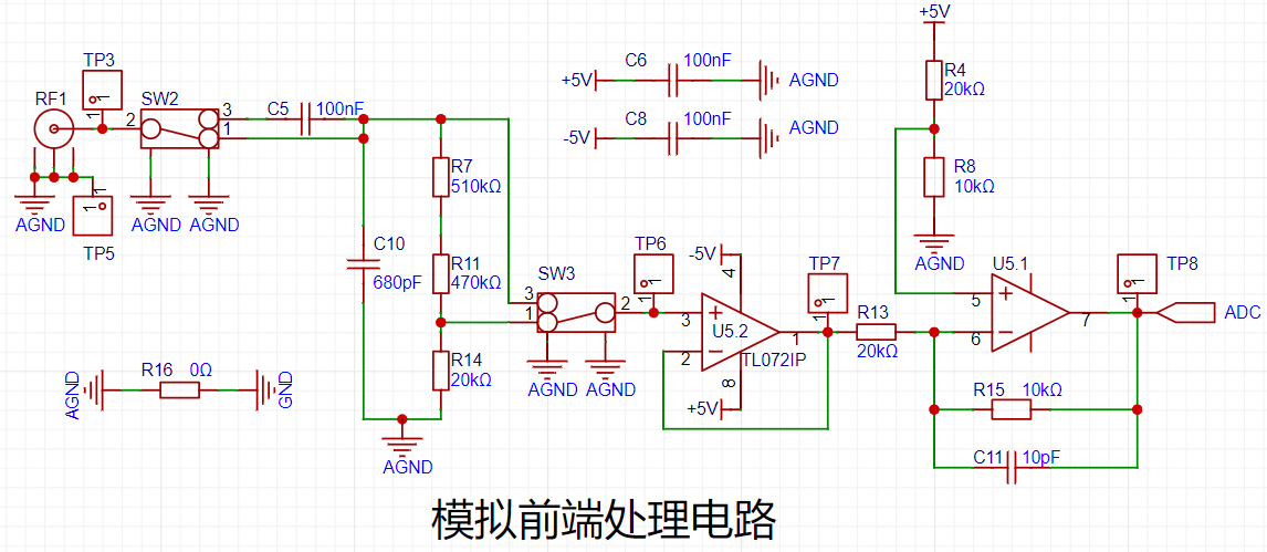

The official raised three questions before explaining the circuit. The following are the corresponding thoughts during the replication process:
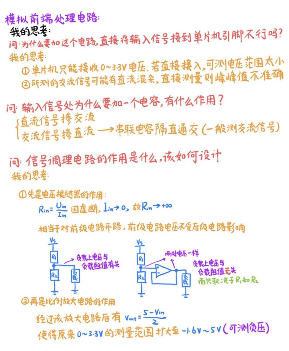

Note! The output of the "comparator frequency measurement circuit" op-amp should preferably be equipped with a 1k ohm pull-up resistor because it is an open-drain output.
2. Power control circuit
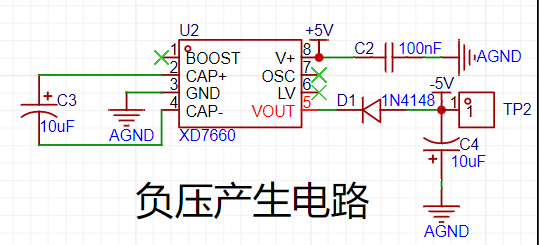
The following is my understanding:
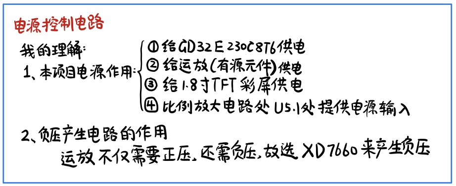
Note!!
The electrolytic capacitor at -5V and AGND in the "negative voltage generation circuit" should have its positive terminal at AGND and its negative terminal at -5V. Note that reversed electrolytic capacitor connection can easily cause the board to explode!
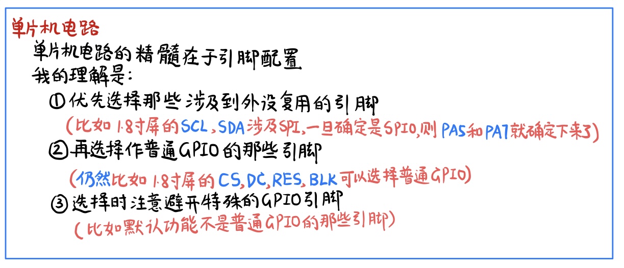
3. Microcontroller circuit
4. Human-computer interaction circuit


When drawing the schematic diagram, please note that there are some minor errors in the schematic diagram part of the Bilibili recorded course. Please see the corresponding comment section on Bilibili for details.
【Part 2】PCB drawing
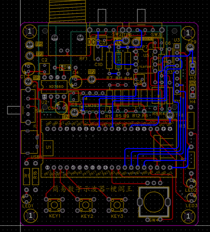
(1) Similar to the schematic diagram, I drew it almost entirely according to the official schematic diagram. All layouts and traces are almost the same as the official one. Except for the slight difference in layout caused by not adjusting the silkscreen size of a certain capacitor and the pad size of the test point when I drew the PCB before the training camp started, there is no major difference from the official PCB diagram.
(2) When routing the power supply to the chip, the power supply line must first pass through the power supply filter capacitor before entering the chip, instead of just connecting all the +5 or all the +3 power supply lines together.
(3) LCSC EDA does not come with a 3D model of a 1.8-inch TFT color screen. Instead, it needs to be manually bound. The binding method is as follows (BV No.: BV1pF4m1V7bG) (about 11 minutes).
The following are the connection diagrams of the front and back sides of the PCB and the copper pouring situation of the front and back sides.


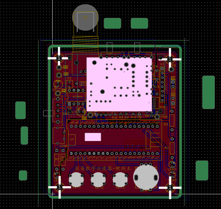
[Part 3] 3D shell
(1) The 3D shell is not a required step in this project. This step is optional. Use LCSC EDA Professional Edition directly to make it. You can refer to the Bilibili video (BV1d8411S7kF) for a detailed introduction. Here I used JLCSC's 30 yuan 3D coupon, so I only paid for the shipping. I'm giving JLCSC a shout-out.
(2) When making the 3D shell, you must consider whether the top and bottom covers can be put together in reality after receiving the shell. For example, the BNC needs to protrude from the shell. At this time, the side groove needs to be half in the upper shell and half in the lower shell.
(3) The three pictures below are the 3D shell's [border layer] [top layer] [preview]
(4) I have a problem here that I did not consider. My 3D model did not take into account the height of the button, so it will be changed later.


[Part 4] Component purchase
precautions:
When I bought the components, I directly clicked "Place order in LCSC Mall" on the BOM table of the official open source project on the LCSC open source hardware platform and the system automatically imported them without separate selection. However, the official open source project is now offline, so you may need to search for the supplier number in the LCSC Mall yourself. Here, pay attention to the following three items:
(1) 1.8-inch TFT display screen.
This should not be available in the LCSC Mall. When drawing the schematic, the supplier number C9900080251 that I searched for cannot be directly placed in the LCSC Mall. The similar product that I bought was the eight-pin socket corresponding to the display screen...
Just search for the keyword "TFT 1.8 128*160" on Taobao.
(2) M3 and M2 hexagonal posts.
They do not affect the functionality. The M2 hexagonal posts are for fixing the display screen. The M2 hexagonal posts can be used to fix the 3D shell at the four corners. I used copper posts for M2 and nylon posts for M3.
(3) BNC to alligator clip probe.
It is not in the BOM and needs to be purchased in advance. Although it does not affect the schematic diagram and PCB, it is needed to verify the PWM output and display of the oscilloscope.
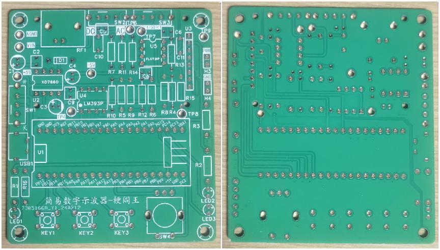
The following are the front and back pictures of the PCB board after it has been made and the situation when the 3D shell is not added:
[Part 5]
Do not pick the wrong resistor when soldering
electrolytic capacitors. Pay attention to the positive and negative
terminals of the chip.
It is recommended to use a knife-edge soldering iron.
See the "Replica Suggestions and Problem Solving" below for details.
How to test the board? Reference (BV No.: BV1sJ4m1Y7Zp (around 45 minutes and 8 seconds)
[Part 6] Burning Code
(1) When downloading the program using GD32 All in One Programmer, if you are directly using LCSC's demo code, you need to compile it first before downloading the hex file, otherwise GD32 All in One Programmer will crash.
(2) Because the code demo in Gitee is constantly being updated, the code displayed on the Bilibili recorded course is different from the demo code in Gitee because the latter version has been updated.
IV. Replicating Suggestions and Problem Solving:
Given that the official documentation and videos are already very detailed, here I will write down my replicating suggestions for beginners like me, as well as the solutions to the problems encountered:
1. Replication Recommendations (Usage of Official Materials):
If you only want to replicate the physical product, theoretically you don't need to understand the circuit principles, but this is one of the essential aspects of this project, so it's best to have some understanding. In addition to the open-source documentation and Bilibili recorded lectures mentioned earlier, I personally recommend combining this with the live replay video "Step-by-Step Guide to Building a Digital Oscilloscope: Hardware Explanation & Q&A" [BV No.: BV1uy421B7Ew] under the "LCSC EDA" account.
For soldering, I recommend watching LCSC EDA's soldering videos on Bilibili first, as videos demonstrate soldering techniques most directly. After watching the videos and memorizing the key points, I suggest checking "1.4 Soldering Practice" in the open-source documentation. The key here is to find a "PCB Soldering Auxiliary Tool" with an HTML extension to minimize soldering errors for beginners.
If you only want to replicate the physical product, you only need to burn the final code in the appendix. For burning instructions, refer to LCSC EDA's official Bilibili course "Project Template Creation" (BV1kw4m1o73g) and the official open-source documentation "2.1". "Development environment setup".
If you want to have a deeper understanding of the code, in addition to learning from the documentation and recorded courses by starting with lighting up an LED, you can download the demo code for each part. It is available on Gitee, the link is at the beginning of this article.
2. Problem solving
The following is about the problems I encountered and their solutions:
(1) Soldering problem
* Resistor soldering error
After ordering directly from LCSC Mall, each component has a supplier number starting with C on its special small bag. When soldering resistors that are easy to get confused, be sure to check the number on the small bag. If you are not sure, you can use a multimeter to measure the resistance value. I made a low-level mistake because of this.
* Forgot to solder the chip socket
This oscilloscope uses three 8-pin chips, which require DIP 8-pin chip sockets when soldering. I only realized after soldering one of them that if the chip is soldered directly, the high temperature during the soldering process may have burned the internal circuit of the chip.
【Solutions to Soldering Errors】JLCIC provides two free board replacements per month, 5 boards each time. So if you don’t mind the board being damaged, you can replace it and resolder it. Otherwise, you can use a desoldering pump. I used a regular manual desoldering pump, which is not troublesome if operated properly. I used two solutions:
the soldering iron was tilted and quickly slid against the soldering error, and the desoldering pump was used to hold the soldering iron
in place to fix the base plate. The soldering iron melted the solder from one side, and the desoldering pump was used to pick up the solder from the other side.
(2) Code Burning Problems
* Problem 1: When following the LCIC EDA Oscilloscope Training Camp video [Software 1], the Software Component is blank at 11 minutes and 14 seconds.
Solution: After checking, I found that the Keil version was too low. Here I chose to follow the tutorial in “2.1 Development Environment Setup” of LCIC’s open source documentation to download the Keil Community Edition.
*Problem 2: The following phenomenon occurs:
After burning the Demo9-screen display experiment code, the bottom and right edges of the screen have several rows of randomly colored dots, but this does not affect the functionality.
Solution: After repeated verification based on the Demo9 code, it was finally found that my screen installation was offset. To achieve the intended effect, the x-coordinate value needs to be increased by 1 and the y-coordinate value by 2. That is, the full screen coverage is not from (0,0) to (160,128), but from (1,2) to (161,130).
*Problem 3: The following phenomenon occurs:
After burning the Demo8 input capture experiment code, the voltage of the PWM 1×2P pin header was measured to be almost 0V. Furthermore, after burning the code for the final case, a multimeter measurement showed that the PWM 1×2P pin header was outputting, but the screen only displayed the interface without showing the waveform.
Solution: I was prepared to resolder the board, but the final solution was surprisingly simple: a multimeter measurement revealed that the voltage was interrupted at SW3, and adjusting it a few times fixed the problem. (i.e., the new switch may need to be toggled several times to turn on)
(3) Open source project display issues

* Problem 1:
As shown in the figure, in the open source project to be released, only the PCB part of the [Design Drawing] section is loaded, but the schematic part is not loaded.
Solution: It is very simple. Re-edit the text description and save it as a draft to refresh it.
* Problem 2:
The PCB part of the released project in the [Design Drawing] section is not displayed as the top layer, but as a 3D layer. I opened the project, readjusted it to the top layer, and exited, but it still displayed as a 3D layer.
Solution: It is very simple. I found that the number of layers displayed in the [Design Drawing] section depends on the number of layers of the last edit of the PCB. Therefore, I moved one pad on the top layer and then moved it back to solve the problem.
V. Code analysis:
(1) For simply replicating the project, it is enough for the code to run normally, but I want to go further and understand the code.
(2) Although I do not have the ability to modify the code now, I can gradually understand it.
The following is a partial analysis:
See the "I Added Rich Comments - Official Final Code Project" in the project attachments for more detailed comments on
the main.c, main.h, led.c
, and led.h files.
The official final example code defines the initialization and switching functions for the two green LEDs, but they are not used yet; we will add functionality to them.
The usart.c and usart.h files
in the official final example code do not seem to directly use the serial port; it is likely used for debugging during the process. The images accompanying
the tft_init.c and tft_init.h files
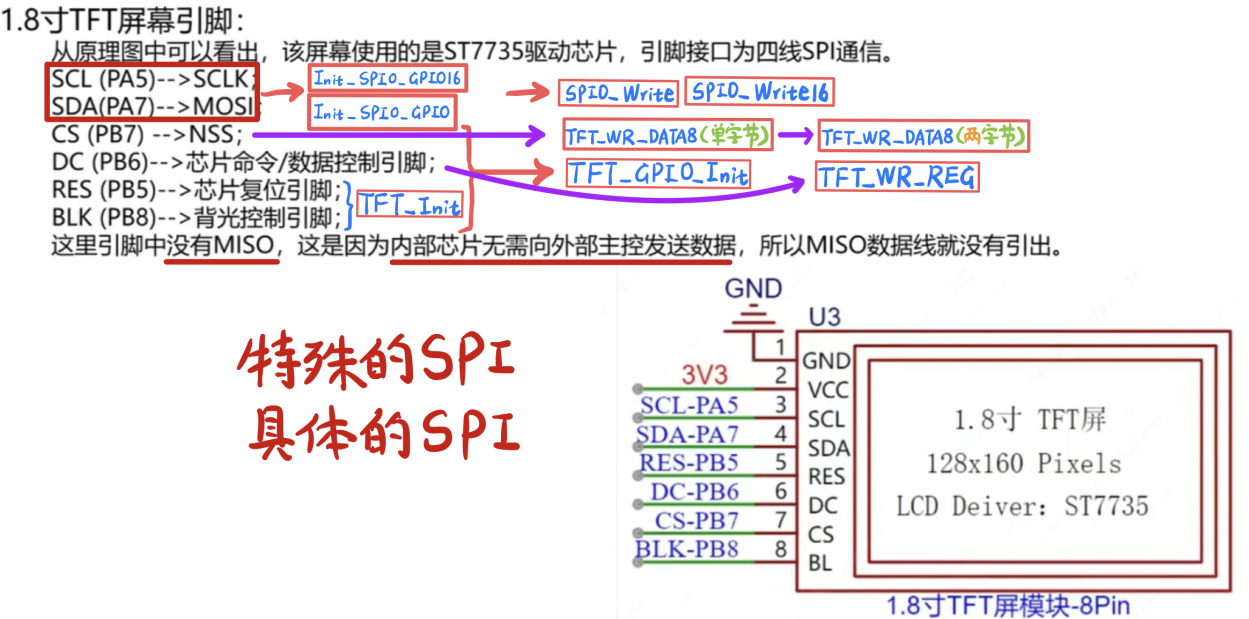
are screenshots from the Bilibili EDA recording course video PPT with my annotations.
For ease of understanding, the images illustrate the approximate relationship between the various functions in the tft_init.c file and the six pins of the TFT that need to be programmed.
Compared to the Demo9 code in the recording course "Screen Display Experiment," the final tft_init.c code has many more functions with "16" after their names, corresponding to a 16-bit data width for SPI0. For example, Init_SPI0_GPIO16 compared to Init_SPI0_GPIO only changes the data width from 8 bits to 16 bits.
The key.c and key.h files
mainly handle three tactile buttons and one rotary encoder.
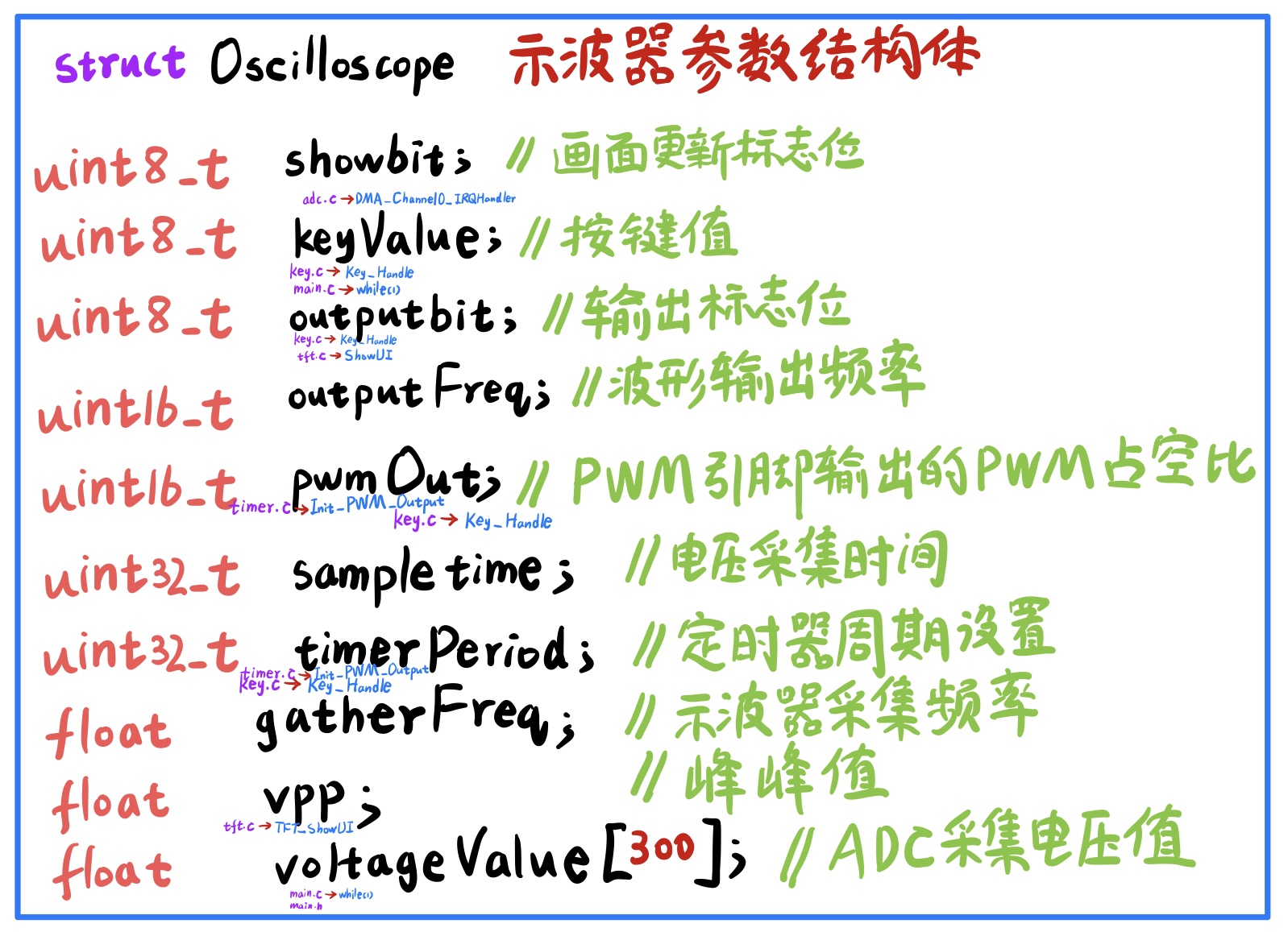
The keyValue variable in the key.c file is not the same as the keyValue variable in the Oscilloscope structure in main.h.
The EXTI of all four—the three tactile buttons and the rotary encoder—is triggered by a rising edge, while the default level is high, indicating that the trigger occurs the instant the button is released after being pressed.
The interrupt sources configured for Init_Key_GPIO and Init_EC11_GPIO are both EXTI4_15_IRQn, which are exactly PB4, PB9, PB13, PB14, and PB15. The PB4 interrupt is triggered by the rotation of the rotary encoder, while the latter four are triggered by the grounding
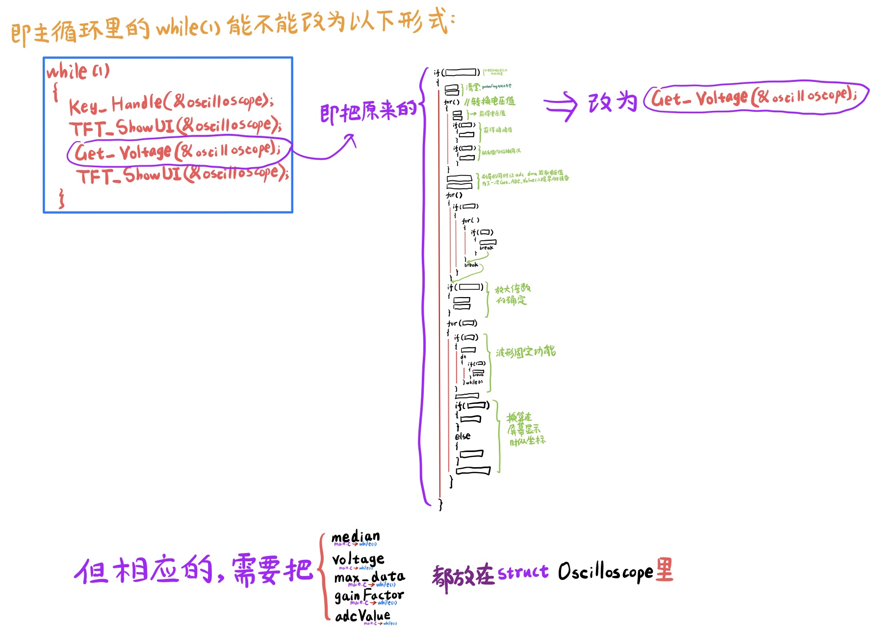
key_Handle function. Each time, the key_Handle function is called first in the while(1) of main.c, and then the voltage acquisition and display steps are performed.
The freq.c and freq.h files
use the general-purpose timer2 to capture the pre-processed signal that is about to be acquired by the ADC. The frequency
division factor setting is very important. According to the official Bilibili recorded course PPT, the clock frequency of the timer used for input capture should be 10 to 100 times the frequency of the signal being measured. The frequency of the input PWM wave here is 1kHz to 4kHz, calculated according to not more than 100 times 1kHz and not less than 10 times 4kHz. The clock frequency of timer2 should be between 4kHz and 100kHz. In the official final code, the divider factor of timer2 is 719, that is, the counting frequency (72M/720) = 100_000Hz = 100kHz, which is exactly the highest value. For
the adc.c and adc.h files
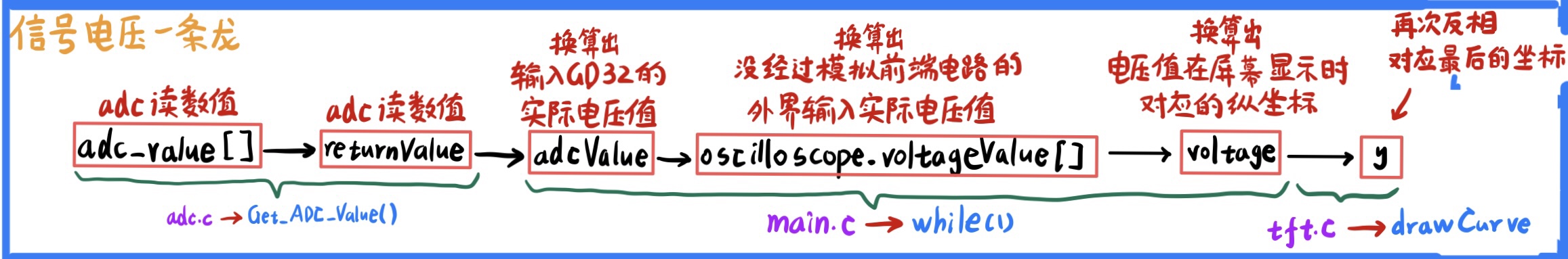
, the Get_ADC_Value function is worth noting. It is responsible for retrieving the data obtained by ADC and DMA from the specified memory area.
It is also important to note the interrupt service function DMA_Channel0_IRQHandler:
after DMA has acquired 300 numbers and entered the interrupt, it will temporarily close the channel and will only reopen it after all the ADC values have been read.
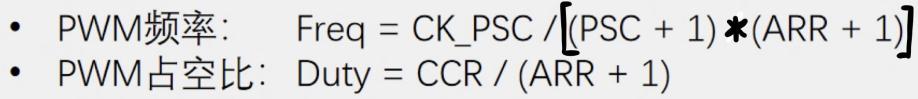
The timer.c and timer.h files
use a general-purpose timer, timer14, to output a PWM wave. The most important formula here is:

The tft.c and tft.h files
contain three important functions: drawCurve, TFT_StaticUI, and TFT_ShowUI.
Regarding TFT_StaticUI, note the following
: A comparison: The "PWM" text in the upper right corner (yellow background, black text) and the "duty cycle" text in the lower right corner (purple background, white text) both belong to static UIs where the bottom bar is wider than the characters, but they are handled differently.
For the former: `
sprintf(showData," PWM ");` //This means pre-leaving spaces before and after PWM.
`TFT_ShowString(110,0,(uint8_t*)showData,BLACK,YELLOW,16,0);
memset(showData,0,32);`
For the latter:
`sprintf(showData," // That is, first a space, then display the duty cycle in ShowChinese.
TFT_ShowString(110,92,(uint8_t *)showData,WHITE,PURPLE,12,0);
memset(showData,0,32);
TFT_ShowChinese(118,92,(uint8_t *)"duty cycle",WHITE,PURPLE,12,0);
The difference between the two is that the former uses English letters, while the latter uses Chinese characters. Therefore, the former can be directly printed using sprintf, but the latter cannot.
Because my screen offset requires adding 1 to the x-coordinate value and 2 to the y-coordinate value, the display of the "simple oscilloscope" and the related code of the leftmost vertical axis of the screen have been slightly adjusted in terms of coordinates.
For TFT_ShowUI, please note the following:
For digital displays, the following three functions are generally used together: sprintf(showData,"%3.0fHz ",(*value).gatherFreq), TFT_ShowString, and memset2.
For Chinese character displays, use TFT_ShowChinese directly.
A minor error in the official final example code (as of March 20th):
In the initialization comments of main.c, the black fill was written as white fill.
The last two functions in adc.h are declared but not used; this is likely because they were forgotten to be deleted during code merging and modification.
In the tft.init.c function Init_SPI0_GPIO16:
SPI_TRANSMODE_BDTRANSMIT should correspond to bidirectional mode, but the comment is incorrectly set to "two-wire unidirectional full-duplex mode" because the function Init_SPI0_GPIO above...
SPI_TRANSMODE_BDTRANSMIT is a single-wire bidirectional half-duplex transmission mode;
and Init_SPI0_GPIO16 is just a change from 8-bit data width to 16-bit data width compared to Init_SPI0_GPIO, but the corresponding structure variable is still marked as 8 bits in the comments. VI
. Improvement Directions (Summary for Beginners, Please Don't Criticize)
Although I am a beginner, I have a desire to improve (not really).
Although I am not capable of making improvements now, I can prepare
the following improvement points in advance. These are basically collected from the official Bilibili recorded course and the discussions I have seen in the group.
[Functional Improvement]
(1) The oscilloscope is changed from a single channel to a dual channel or even a multi-channel.
(2) Add a signal generator function. At this time, in addition to the minimum system board, an external DAC module is also required.
[Circuit Improvement]
(1) Improvement of input signal attenuation circuit: ×1/50 attenuation is not practical for this project because for voltages of 5V~25V, using ×1 will exceed the limit, and using ×1/50 will attenuate to 0.1~0.5V, making it susceptible to interference and inaccurate. It can be adjusted to 1/3, that is, the resistance values of the three voltage divider resistors in the corresponding circuit (analog front-end processing circuit -> voltage attenuation circuit) can be adjusted by yourself. (However, the sum of the resistance values of the three resistors needs to exceed 1MΩ)
(2) Improvement of signal conditioning -> proportional amplifier circuit: The relationship between Vout and Vin can be changed by adjusting the resistance values (but the resistance values still need to meet certain constraints after adjustment)
(3) Improvement of comparator frequency measurement circuit: The threshold voltage U+ of the hysteresis comparator can be made higher and U- lower by adjusting the resistance values, thereby improving the frequency measurement effect (but the resistance values still need to meet certain constraints after adjustment)
[Schematic diagram improvement]
*If you are not satisfied with the schematic diagram of the component, you can modify it in the library. For example, the LED pattern can be filled with red or green to emphasize the LED color; the test point pattern symbol can be reduced to make the schematic diagram more aesthetically pleasing.
[PCB Improvement]
(1) If you are not satisfied with the PCB layout of the component, you can modify it in the library. For example, the size of the test point pad can be reduced (the multimeter needle can probe in); the capacitor silkscreen border is larger than the actual component size, so it can also be reduced.
(2) When switching between the front and back sides, there can be two vias to enhance the current carrying capacity, but you need to close the wiring -> remove the loop.
[Component Selection Improvement]
Through-hole components become surface mount components. (Each has its advantages and disadvantages)
*Through-hole components are easy for beginners to solder and take up a lot of space;
*Surface mount components take up little space, and soldering requires more than just a soldering iron
. The core board and screen do not need to be socketed. (Each has its advantages and disadvantages)
*The advantage of using a socket header is that both the screen and GD32 are plug-and-play, but it lacks customization.
* Direct integration without a socket header offers sufficient customization, but has lower fault tolerance .
Probe modification:
The original BNC to alligator clip probe can be replaced with a passive probe from a professional oscilloscope. This allows for preliminary signal attenuation using the probe's built-in ×10 range, instead of relying solely on the attenuation circuit.
[Code Improvement]
*When the waveform is fixed, the program directly enters an infinite loop, preventing other operations. For example, pressing a button is ineffective when the waveform is fixed. However, this isn't a major issue; it should be fine without adding new features.
VII. Attachment Directory:
[Original Version - Official Final Code Project] The official final project downloaded from Gitee on March 20th, which I haven't modified.
[My Version with Rich Comments - Official Final Code Project]
[Code Learning Notes] Contains incomplete records; please refer to the included readme for details.
The [3D Shell Package] provides 3D shell files, with file extensions STL, STEP, and OBJ available for immediate use.
The [Illustration Package] contains all the images described herein. The
[Demo Video] is only 20 seconds long and slightly blurry due to the 50MB size limit for each attachment; please understand.
The [Illustration Video with 3D Shell] is only 4 seconds long and serves as proof of the shell's functionality. See the "Demo Video" for a full demonstration of the features.
This is a voltage and current meter made using a CW32F003E4 microcontroller. The microcontroller has a main frequency of 48MHz and a very stable 12-bit ADC peripheral, which provides the possibility of making a high-precision current and voltage meter.


 An LDO is used for buck conversion; however, voltages above 12V have not been tested as the LDO may overheat. The system is based on an STM32F103C6T6 main controller, and can be directly programmed using a GD32F103C8T6. Currently, it is tested to be compatible with GD/ST chips of the same series. Due to its simple functionality and software-implemented protocols, it is expected to be directly compatible with other domestically produced chips.

 Code and schematics open source link: https://github.com/RealCorebb/bbMonitor
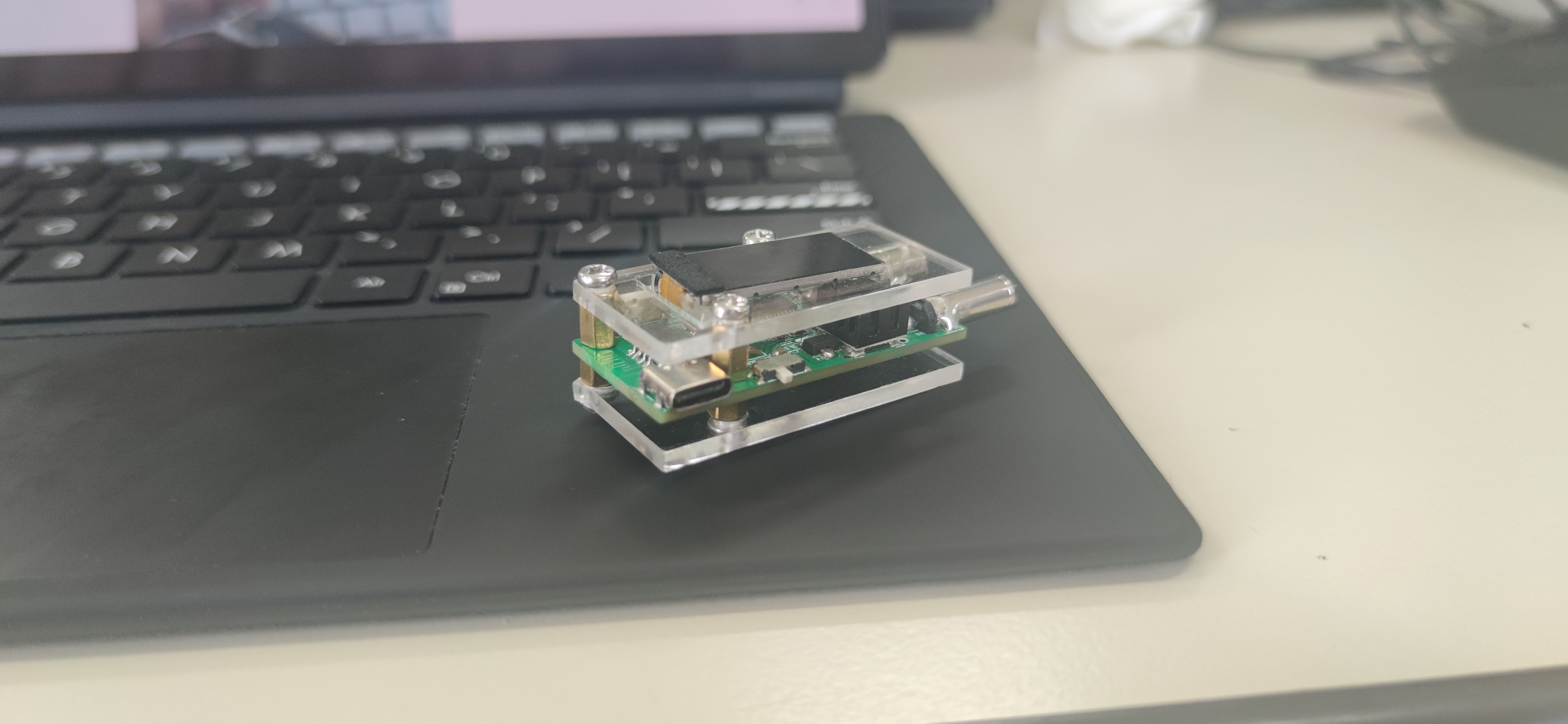


 京公网安备 11010802033920号

 XC6104C030


