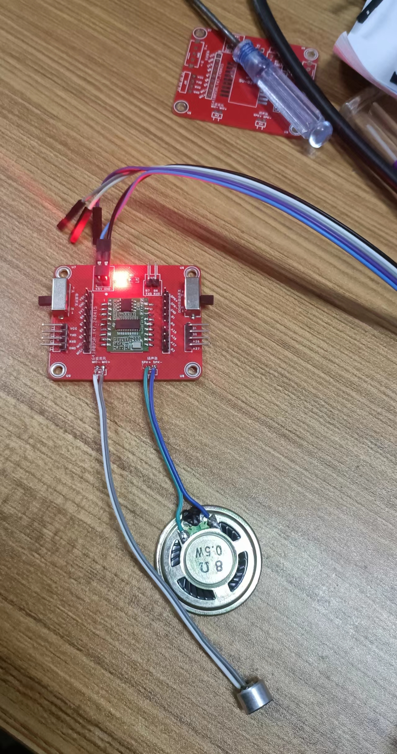
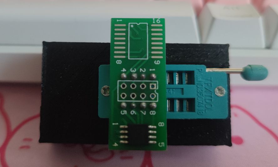
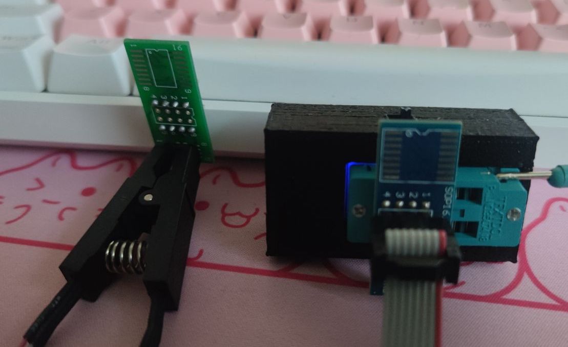
This project was primarily designed because the SU-03T module's development board has a 2mm pin pitch, while my commonly used DuPont wires and other modules have a 2.54mm pitch. Furthermore, programming the SU-03T using a CH340 requires unplugging and replugging the GND pin, which is cumbersome. Therefore, I designed a simple expansion board to control the SU-03T's power-on, power-off, and cold-start processes during programming via a toggle switch.
This project uses a 45° copper pour, mainly because I hadn't tried 45° before when designing boards, and this was an opportunity to test its effectiveness.
Testing showed that the expansion board works correctly and achieves cold-start functionality via the toggle switch. Compared to the first version, the second version adds an SS34 in series for reverse power supply protection. **
Note:** Please use this project with caution. I have limited PCB design experience, and there may be shortcomings in routing and layout. I hope experts can provide guidance.
PDF_SU-03T Expansion Board.zip
Altium_SU-03T Expansion Board.zip
PADS_SU-03T Expansion Board.zip
BOM_SU-03T Expansion Board.xlsx
95115
Small gamepad v1 based on ESP32C3
A small gamepad based on the ESP32C3, costing approximately 25 yuan.
The schematic diagram for this project is from https://oshwhub.com/djzrs/he-zhou-esp32c3-shou-bing-ti-dai-wl-hong-wai-ban.
It has been modified and rearranged, adding a screen, casing, and other components. It's
a small gamepad based on the ESP32C3,
connecting to the computer via Bluetooth.
Optional automatic joystick position calibration is available . Non
-standard components used include:
IIC SSD1306 (OLED screen) *1,
standard keyboard switch holders and switches *4,
13*13 size joystick (with buttons) *2
, Hezhou ESP32C3 development board *1,
M3*6 (or shorter) screws *6
(other components can be found on the PCB).
Note:
Two rows of 16-pin headers should be soldered to the development board for easy insertion and removal. The 4-pin header is for inserting the 13*13 size joystick
of the SSD1306 module. Don't be tempted by cheap options! (I bought two cheap ones (around 3 RMB) from a certain online store, and both had extremely serious drifting, with the joysticks visibly misaligned...) When using the Heze ESP32C3 development board, you must unlock GPIO11 (otherwise, pressing the right joystick will short-circuit). 3D shell file address: https://makerworld.com/zh/models/44344. You can print them using your own FDM 3D printer (costing only a few cents). Print one for the top cover and one for the bottom cover. The code was developed using Arduino (a patchwork of various routines) . It's still under development; a test version is currently released (see attachment ). The project has little commercial value, and the code is poorly written, so I just packaged it up and released it directly.
arduino code.rar
PDF_Small Gamepad Based on ESP32C3 v1.zip
Altium_Small Gamepad Based on ESP32C3 v1.zip
PADS_ESP32C3-based Mini Gamepad v1.zip
BOM_Small Gamepad Based on ESP32C3 v1.xlsx
95116
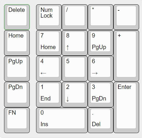
CaiZiMao DS 22-keyboard wired numeric keypad QMK VIA
Numeric keypad based on QMK, supports VIA key remapping.
This is a numeric keypad based on QMK, supporting VIA key remapping.
The PCB size is 9.9*9.9.
Free
3D printing of the outer shell is available monthly from JLCPCB. Shell files are available here: https://makerworld.com/zh/models/436056#profileId-341157
Taobao link: https://item.taobao.com/item.htm?id=786180422801&spm=a213gs.v2success.result.1.614f48313TRlEk&skuId=5539174123371
QQ group: 677654482 (various file downloads).
Default layout
real-life images
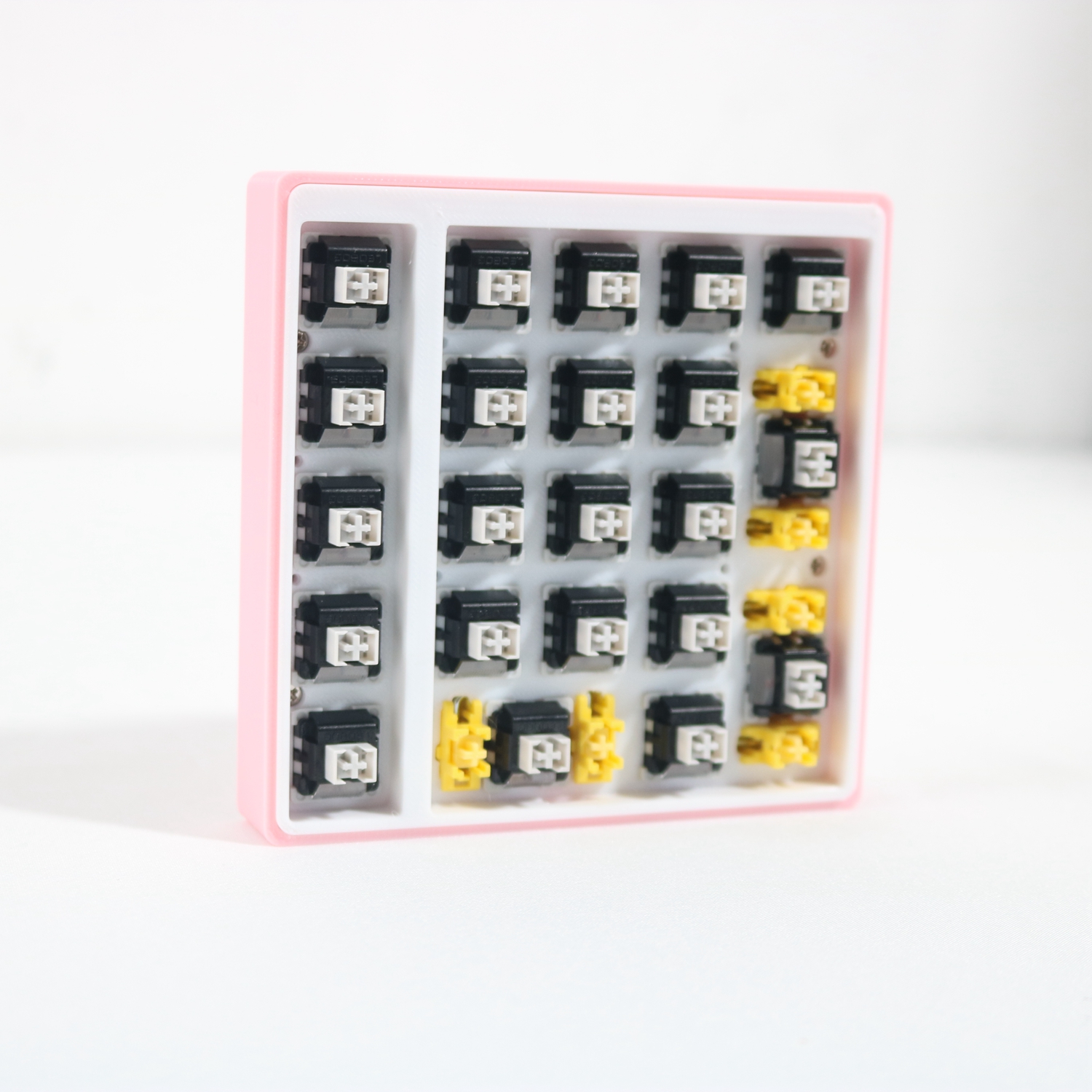
are included. Flashing:
Use J-Link to burn the BootLoader
, then use QMK-toolbox to flash DS22.bin. Download address: https://github.com/qmk/qmk_toolbox/releases
VIA https://usevia.app/importmao_ds22_via.json
Caizi Cat DS22.stp
Gerber_DS22_QMK_V1.0_2024-04-20.zip
DS22_QMK_V1.0_2024-4-20.html
BOM_DS21_QMK_V1.0_DS21_QMK_V1.0_2024-04-20.xlsx
mao_ds22_via.json
0mao_ds22_via.bin
generic-none_bootloader for STM32-87.bin
PDF_CaiZiMao DS 22-key keyboard with wired numeric keypad QMK VIA.zip
Altium_菜籽猫 DS 22-key keyboard with wired numeric keypad QMK VIA.zip
PADS_菜籽猫DS 22keys keyboard with wired numeric keypad QMK VIA.zip
BOM_菜籽猫DS 22-key keyboard with wired numeric keypad QMK VIA.xlsx
95119
The ESP8266 mini-program perfectly supports weather, clock, WiFi, TV, and photo album.
Interact with the Mini TV via WeChat mini-programs or web pages to enhance its playability.
The new version supports direct photo uploads from mini-programs to the Mini TV.
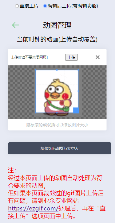
The web version firmware also allows you to upload GIFs anytime, anywhere—no more being stuck with the same old astronaut; upload whatever you want!
Project Description:
This project uses Espressif's ESP8266 as the main controller to drive a 1.54-inch TFT LCD screen. It utilizes capacitive touch buttons, WS2812 LED lights, and a buzzer to create a popular WiFi weather clock desktop decoration. In addition to the standard weather clock functionality, this project adds a photo album function, allowing users to upload and delete photos with a single click via a mini-program or webpage, further enhancing its practicality. Capacitive touch buttons are also added for switching interfaces, increasing ease of use and interactivity. The addition of WS2812 LED lights adds a cool effect to the small TV, offering various ambient lighting effects: fixed color; fixed color breathing light; and fixed brightness gradient color. A buzzer is added to function as an alarm clock, a long-awaited and practical feature. It supports setting up to three alarms, each with options for: single alarm, weekday, and daily alarms, sufficient for daily use.

The project features
automatic WiFi connection, allowing users to set and modify WiFi usernames and passwords via a mini-program or webpage, eliminating the hassle of changing locations – one of the reasons I dedicated myself to this project.
It displays the time using automatic WiFi synchronization, ensuring accuracy, and allows setting the time zone within the mini-program or webpage, making it usable even abroad. It
displays weather information by retrieving real-time weather data from a weather website, with the mini-program or webpage supporting city/location modification.
Multiple clock and weather interface themes are available, switchable via buttons, the mini-program, or the webpage – there's one to suit your taste.
Text color is adjustable, allowing you to change the text color freely within the mini-program or webpage, changing your mood with a different color.
A photo album function allows users to upload or delete images via the mini-program or webpage, and edit uploaded images, including zooming, shrinking, and cropping.
Brightness is adjustable, recognizing different screen brightness needs, so a function to adjust and save brightness within the mini-program or webpage is included. To facilitate nighttime use, a night mode has been added. Once set, the mini TV can automatically adjust its brightness at set intervals, making it more user-friendly.
Ambient lighting effects are also included; the added WS2812 chip allows for fixed color, breathing light, and gradient color effects, eliminating the need to purchase a separate ambient light fixture for a cool look.
An alarm clock function has been added, featuring a buzzer that can be used as an alarm. Don't assume a buzzer only makes a "bi~bi~" sound; the built-in "Ode to Joy" theme song will give you a new perspective
on buzzers. The alarm clock supports several common modes: single ring, weekday ring, and daily ring. The astronaut GIF in the lower right corner can be freely changed. The web version 3.0 firmware adds the ability to replace GIFs, a significant upgrade. This function allows uploading GIFs up to 80*80 pixels and 100KB to the webpage, or using the webpage's built-in editing functions to upload any GIF, which can be scaled, cropped, and automatically adjusted to the appropriate pixels and size. This feature makes the mini TV more than just a monotonous rotating astronaut; various anime and cartoon characters can be freely uploaded.
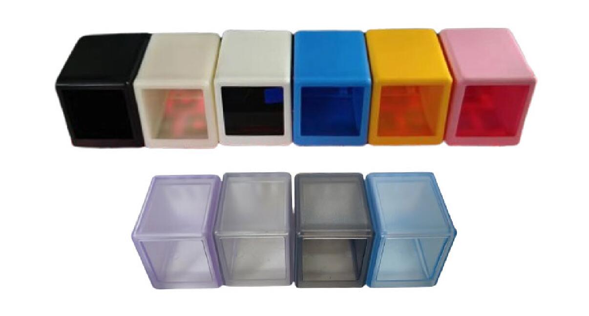
The firmware also supports certain inverted color screens;
it also supports mirrored display, so you can create a transparent mini-TV with a prism;
some customized firmware versions also support stock quotes, computer performance monitoring, timers, etc.;
an optional lithium battery rechargeable version is available;
related links :
v1.x version -- using the mini-program for interaction allows for many settings: https://www.bilibili.com/video/BV1a3411m7rJ/
v2.1 version -- adding album functionality using the mini-program for interaction: https://www.bilibili.com/video/BV1A54y1g7yU/
v3.0 web version -- using the ESP8266's built-in web interaction, adding GIF upload: https://www.bilibili.com/video/BV1TG411D76i
v3.0 web version user guide: https://www.bilibili.com/video/BV1A54y1g7yU/
"Beginner's Guide to Replicating" https://www.bilibili.com/read/cv22449803/
Project Attributes:
The hardware portion of this project references Misaka's "SD2 Mini TV Open Source Project," xutoubee's "ESP32 Desktop Mini TV Open Source Project," and Zhihui's "HoloCubic Open Source Project."
The software code, v2.x and v3.0, is my original work.
Project Progress :
2022.12 Replicated the SD2 Mini TV and HoloCubic Mini TV.
2023.1 Started writing v1.0 Mini TV firmware (source code referenced from Misaka's source code and some of xutoubee's source code), and simultaneously wrote and released the mini-program code; both the firmware and the mini-program are free.
2023.2 Abandoned the original code, rewrote the program, supporting photo album, OTA upgrades, buttons, color lights, etc., and continued to use it for free.
November 2023: The original code and the mini-program platform were abandoned again. A web-based 3.0 firmware was developed and released. The new firmware added GIF editing and uploading capabilities, a completely new UI, and improved performance while increasing functionality. The mini-program version firmware and mini-program were retained, maintained, and made available to users free of charge.
January 2024: An English version of the web-based firmware was developed and released, supporting global weather information.
April 2024: A lithium battery charging version was added to the hardware, with firmware supporting power display and energy-saving functions.
The hardware design
system block diagram shows
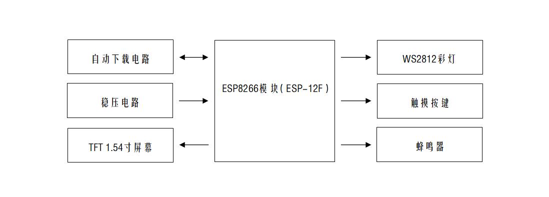
the voltage
regulator circuit using the classic AMS1117-3.3 chip, with 10uf capacitors for decoupling at the input and output.

The automatic download circuit
uses the classic CH340C solution, cleverly utilizing two transistors and leveraging the microcontroller's download mode to achieve one-click automatic download. Those interested in the principles can search on CSDN; most explanations are quite good. Actually, you can also use chips like CH340K or CH340X. They don't require transistors or other external components; you only need resistors and capacitors. This project uses CH340C because the SOP-16 package is easy to solder, making it easier for beginners to use.

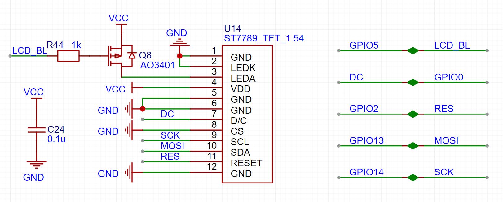
The TFT screen display circuit
uses a 1.54-inch LCD screen. The 0.7mm ribbon cable is relatively easy to solder, and currently costs around 8 yuan, which is inexpensive and very suitable for replication. An AO3401 MOSFET is used to control the screen backlight.
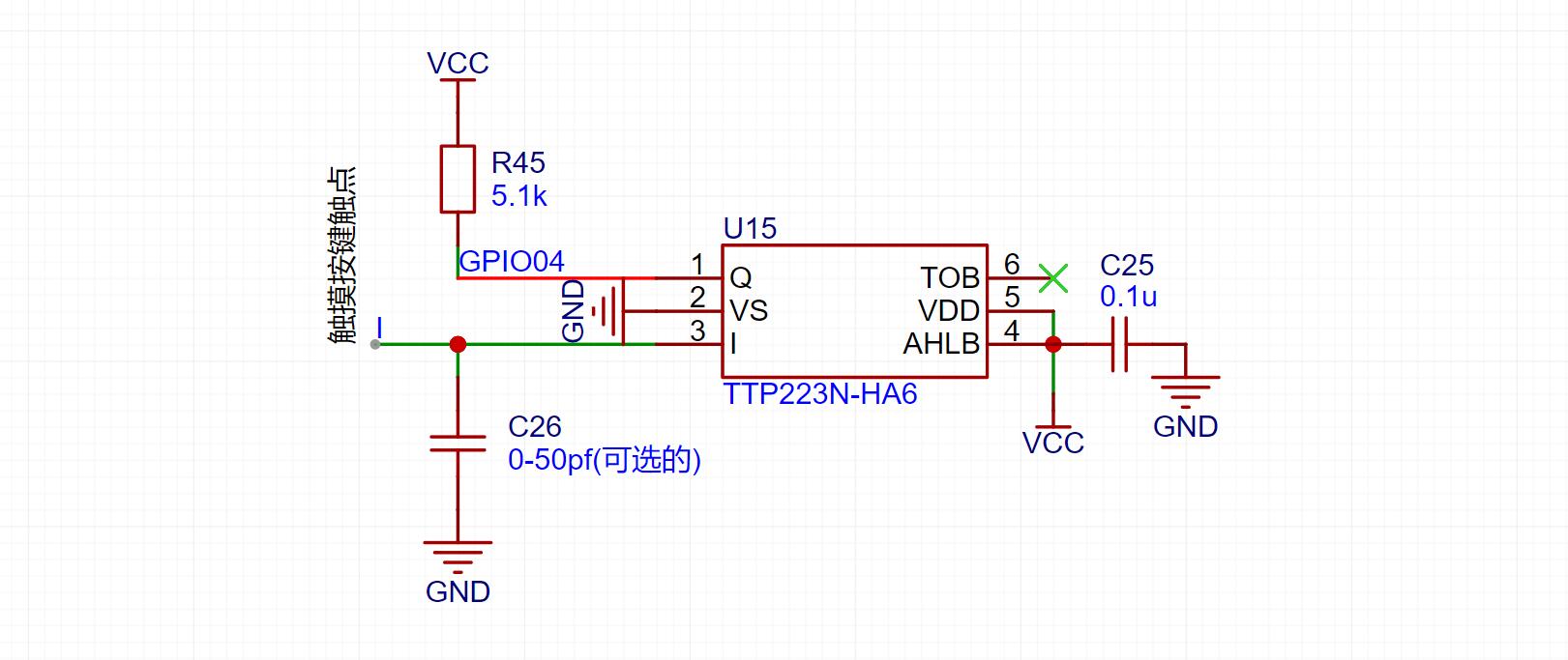
The capacitive touch buttons
use the TTP223 chip to implement the touch button function. This chip only requires one capacitor and one resistor, and the sensitivity is quite ideal. Note that the 0-50fp capacitor is normally not soldered unless the sensitivity is particularly poor, in which case you can add this capacitor to test it. Alternatively, you can directly buy a touch button module for this part; it only costs a few cents. Purchase links are available in the "Replica Components Links" section of the project attachments.
The ambient light uses a WS2812 programmable LED. This LED only requires one data input to control the display of various colors, which is very convenient.

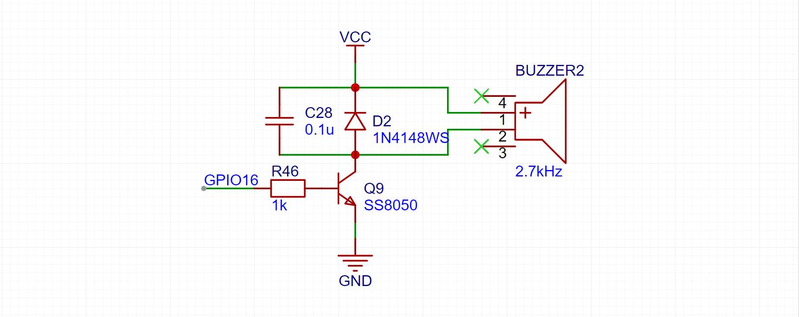
The buzzer uses a 75*75 SMD passive buzzer, and the firmware can drive it to play rhythmic tones (currently with "Ode to Joy" built-in). This part of the circuit uses a transistor to amplify the driving capability, and also uses a diode for current conduction. Those familiar with passive buzzers may have encountered situations where the buzzer gets very hot to the touch. This is because a passive buzzer is essentially an inductor; the voltage can reach several volts or even tens of volts when the power supply is stopped. If this voltage isn't released, it could burn out the buzzer or even other components. It's best not to omit this diode. The
software
program mainly consists of: WiFi connection, time server synchronization, obtaining and parsing weather data, UI display, button control, color light control, buzzer control, image reception and saving, and OTA upgrade. This section will mainly focus on image uploading and OTA upgrades. For other parts, refer to the open-source code of this project and some library examples.
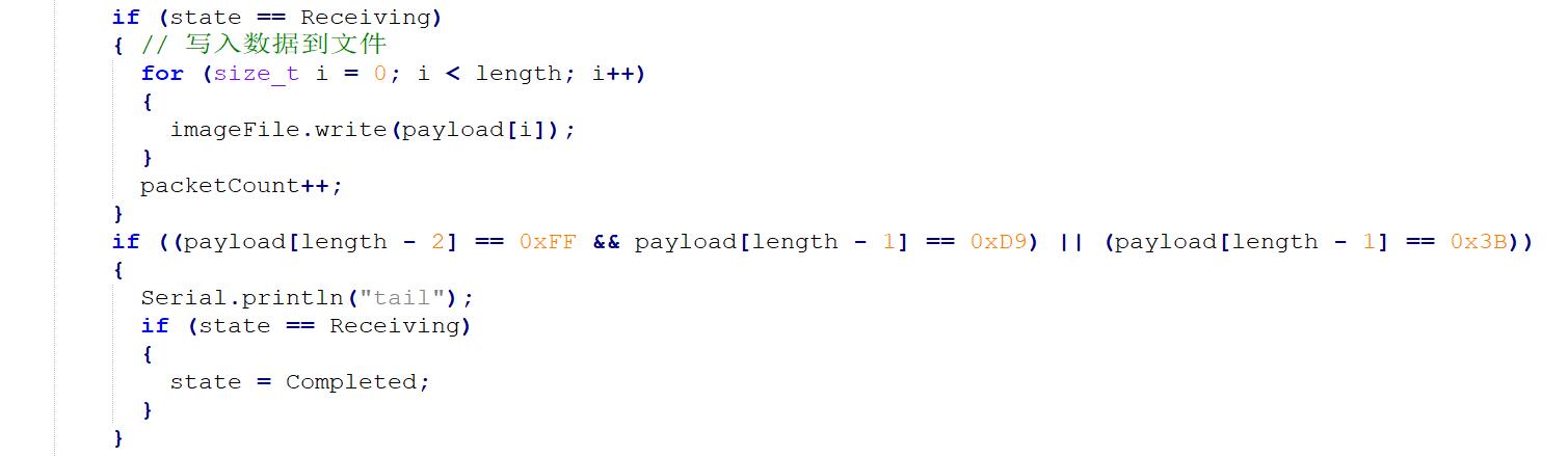
Image reception and saving
involves directly storing data sent from the mini-program or webpage to a file.
OTA upgrades
are also very simple; it's just the example code, requiring no modification.

The casing uses a classic open-source mini TV casing, which is simple and beautiful. The 3D printing files are attached. Injection molded casings are also available; you can find the link in "Replica Components Links". The package includes:
casing display
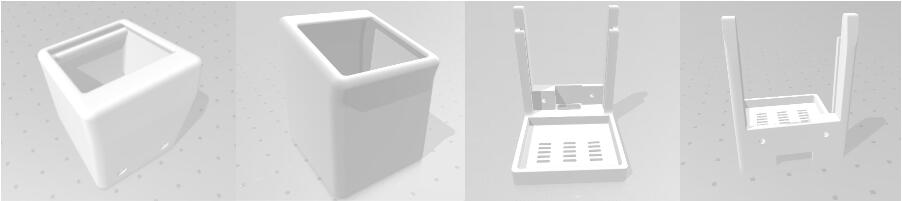
, physical demonstration,
weather clock, UI interface,
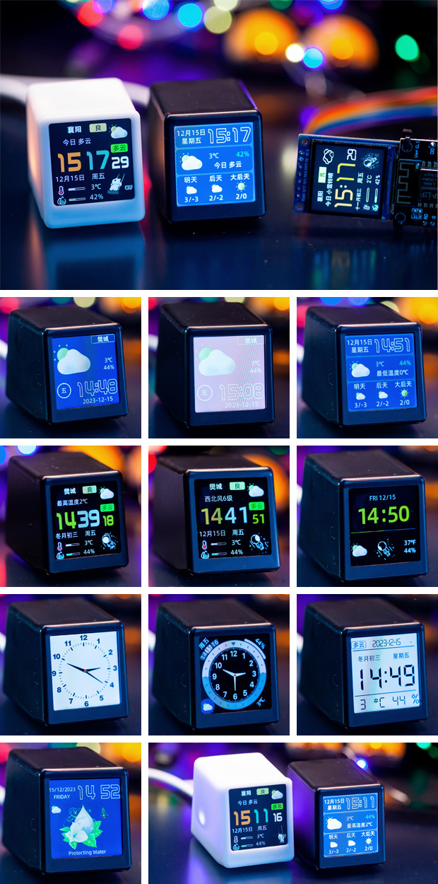
font color settings , photo

upload,

GIF animation upload,
and mutual assistance/communication.
I have created several QQ groups to discuss problems and experiences encountered in replicating and using the mini TV.
Group 1: 744565357, Group 2: 319163806, Group
3 : 3036979;

Thanks
to JLCPCB for letting me get so many PCBs for free, and for letting me continue to get more for free -_-;
Thanks to Misaka for the open-source project "Super Beautiful Personal Clock Weather Station SD²", link: https://oshwhub.com/MisakaBanBan/small_desktop_display;
Thanks to xutoubee for the open-source project "ESP32 Desktop TV", link: https://oshwhub.com/xmz0916/esp32-desktop-tv
; Thanks to Zhihui for the open-source project "HoloCubic--Multifunctional Transparent Display Desktop Station", link: https://github.com/peng-zhihui/HoloCubic;
Thanks to all the friends in my group for their continued support!
studio_video_1705060501101.mp4
QQ short video 20240407124927.mp4
Replica Component Links.xlsx
Little Beginner's Guide to Replicating a Mini TV.pdf
3D Shell.rar
Small TV Reference Source Code.rar
PDF_Master the ESP8266 Weather Clock WiFi Mini Program Photo Album (Perfectly Supported) .zip
Altium_Control Mini Program ESP8266 Weather Clock WiFi Mini TV Photo Album Perfectly Supported.zip
PADS_Control Mini Program ESP8266 Weather Clock WiFi Mini TV Photo Album Perfectly Supported.zip
BOM_Master the ESP8266 Weather Clock WiFi Mini Program Photo Album perfectly.xlsx
95120
Raspberry Pi Pico Enhanced Edition
A replica of the Raspberry Pi Pico, version 1.0 has a minimum package size of 0603 (except for a few ESD transistors, which can be left unsoldered), and version 1.1 has a minimum package size of 0402. To compensate for the lack of a DAC in the RP2040, a space was specifically reserved for dual op-amps.
0x00 Why did I make this?
Recently, the price of Pico from Hezhou has doubled, and I couldn't hold on any longer. After carefully examining the circuit, I realized that the Flash capacity wasn't even fully utilized.
PDF_Raspberry Pi Pico Enhanced Version.zip
Altium_Raspberry Pi Pico Enhanced Version.zip
PADS_Raspberry Pi Pico Enhanced Version.zip
BOM_Raspberry Pi Pico Enhanced Edition.xlsx
95122
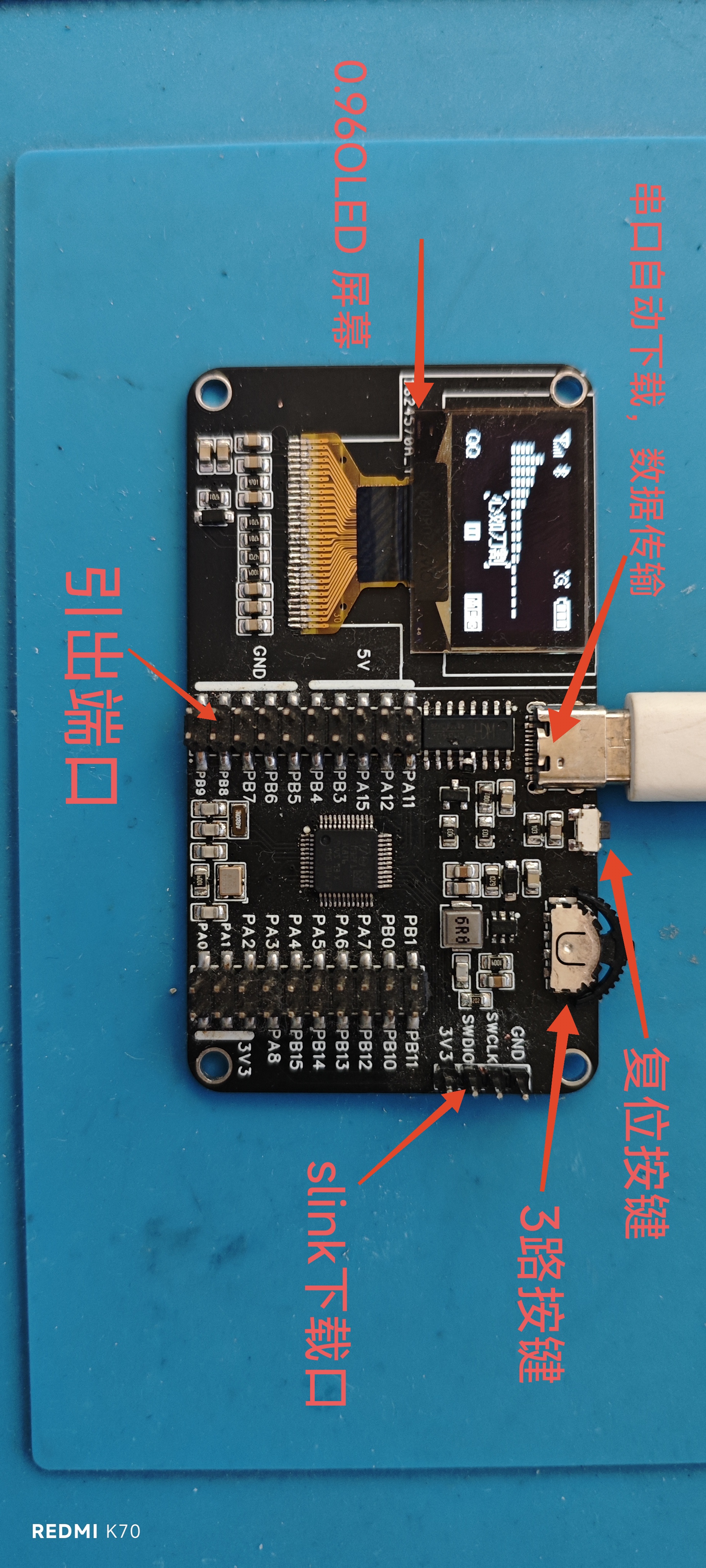
STM32 development board (with serial port download, screen, and buttons)
STM32 development board with automatic serial download, serial data transmission, 0.96 OLED screen, and 3-way button.
1. Based on the original design, a 0.96-inch OLED (SCL PB8, SDA PB9), dial buttons (PA12, PA11, PA8), and a serial port automatic download circuit (serial port can download programs and transmit data) have been added.
2. It supports both serial port and Stling download. During this process, there is no need to change the boot options of boot0 and boot1. The
included STL format 3D printed shell
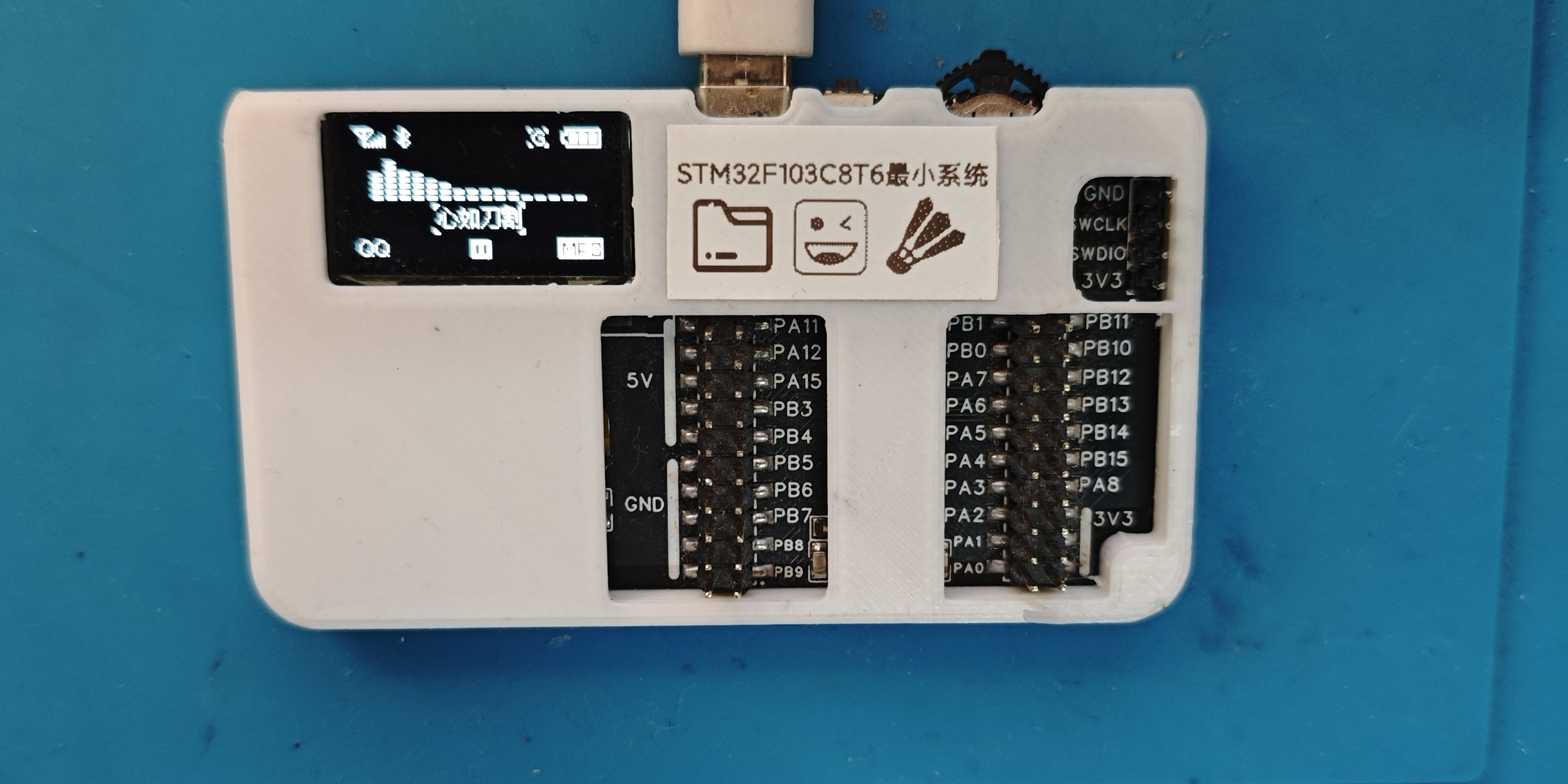
makes it more flexible and versatile. Programs can be downloaded using Stling, and the running results can be displayed on the screen, or the processed results can be read via serial port

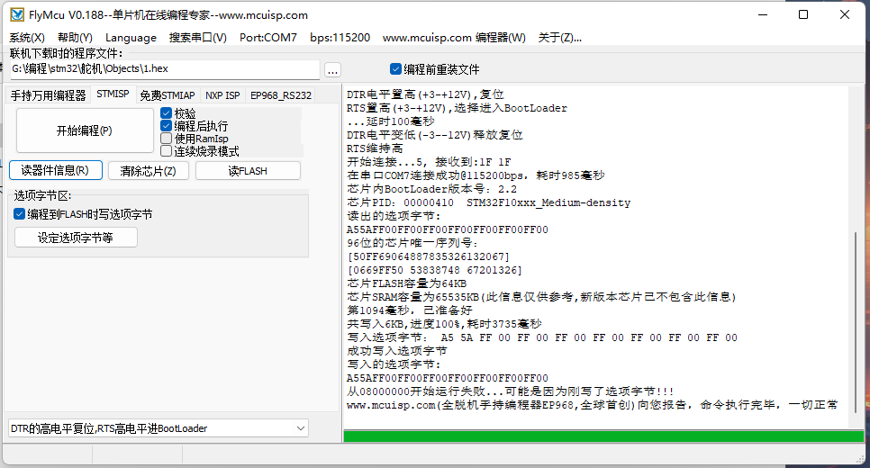
. For serial port download, select DTR high level for reset and RST high level for booting. After clicking "Start Programming," press the reset button on the development board to begin downloading.
For Stling download, after the program download is complete, press the reset button on the development board to start program execution.
Serial port download.zip
Development board v1.stl
PDF_stm32 development board (with serial port download, screen, and buttons).zip
Altium_stm32 development board (with serial port download, screen, and buttons).zip
PADS_stm32 development board (with serial port download, screen, and buttons).zip
BOM_stm32 development board (with serial port download, screen, and buttons).xlsx
95124
Arduino Development Board - DIY Uno
Arduino Development Board - Homemade
The expansion pins added to the original board eliminate the need for additional expansion boards, making it convenient for DIY projects of various kinds.
PDF_Arduino Development Board_DIY uno.zip
Altium Arduino Development Board - Homemade Uno.zip
PADS_Arduino Development Board_DIY uno.zip
BOM_Arduino Development Board_DIY uno.xlsx
95125
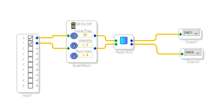
ADAU1701 DSP Verification Board
SigmaDSP
The system
introduces all digital inputs and outputs (MP0-MP11). The ADC and DAC are brought out as headphone jacks.
A jumper cap can be used to select PLL and BOOT modes.
The onboard EEPROM limits
I2S input, requiring an external MCLK. The interface is not brought out. Programming
can be done in two ways:
1. via MCU (
GitHub link
); 2. via USB (see attachment). A simple
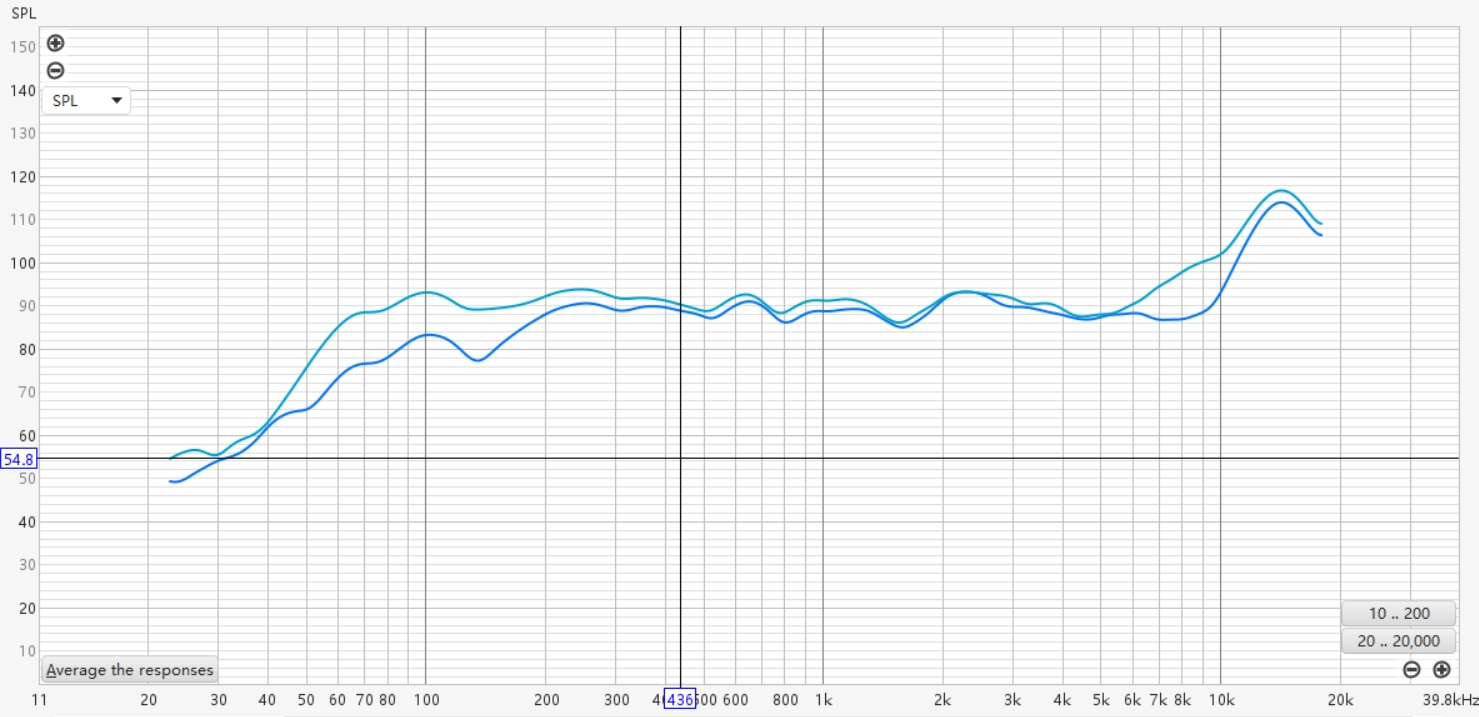
verification is provided
: use Super Bass and EQ to enhance low and high frequencies, and compare the frequency response curves before and after (the recording equipment is not professional and is for reference only).
freeUSBi.pdf
PDF_ADAU1701 DSP Verification Board.zip
Altium_ADAU1701 DSP Verification Board.zip
PADS_ADAU1701 DSP Verification Board.zip
BOM_ADAU1701 DSP Verification Board.xlsx
95126
SPI nor Flash wireless high-speed programmer ESP32-S3/C3
A high-speed wireless programmer based on ESP32-S3/C3 SPI nor Flash.
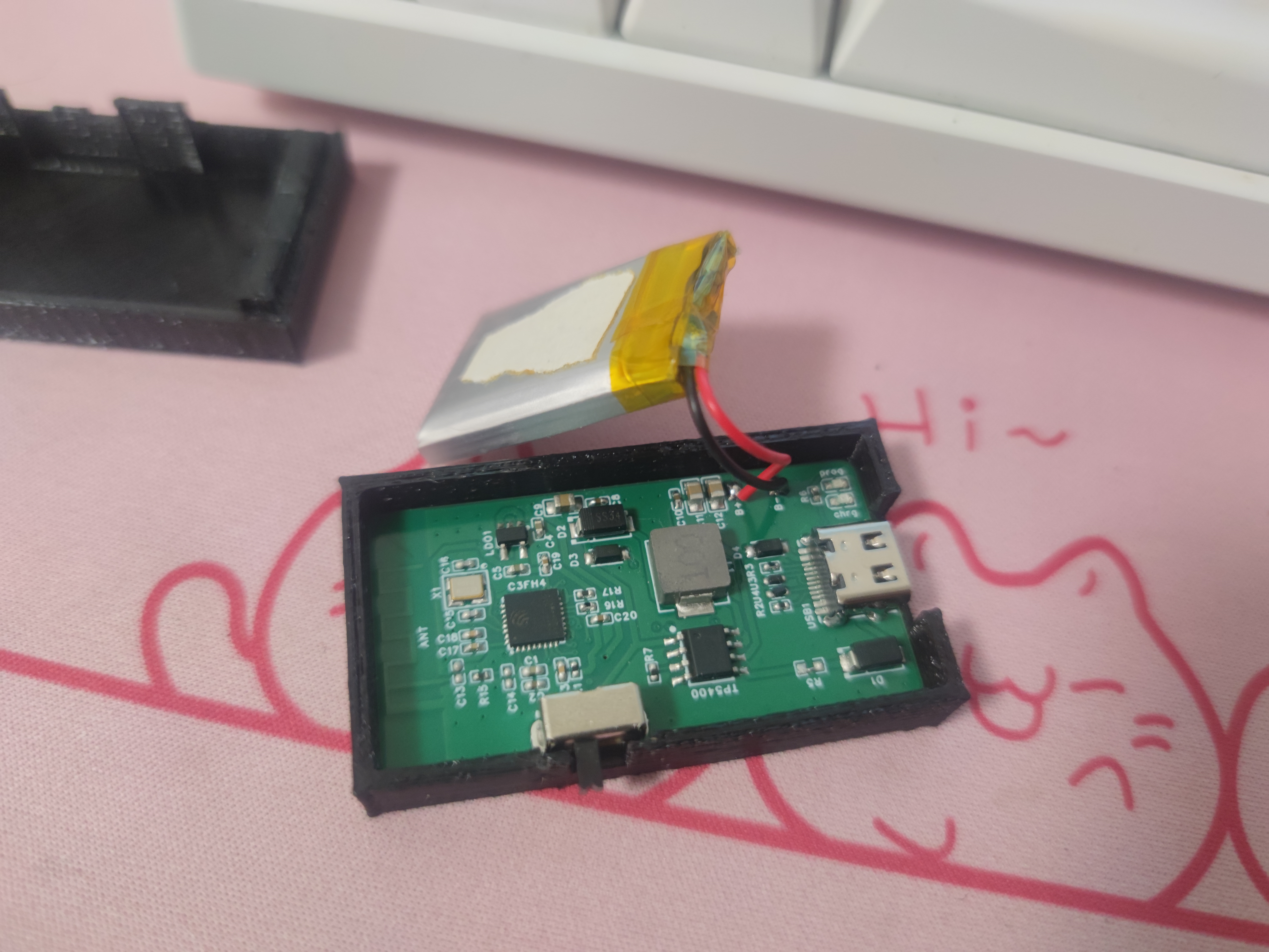
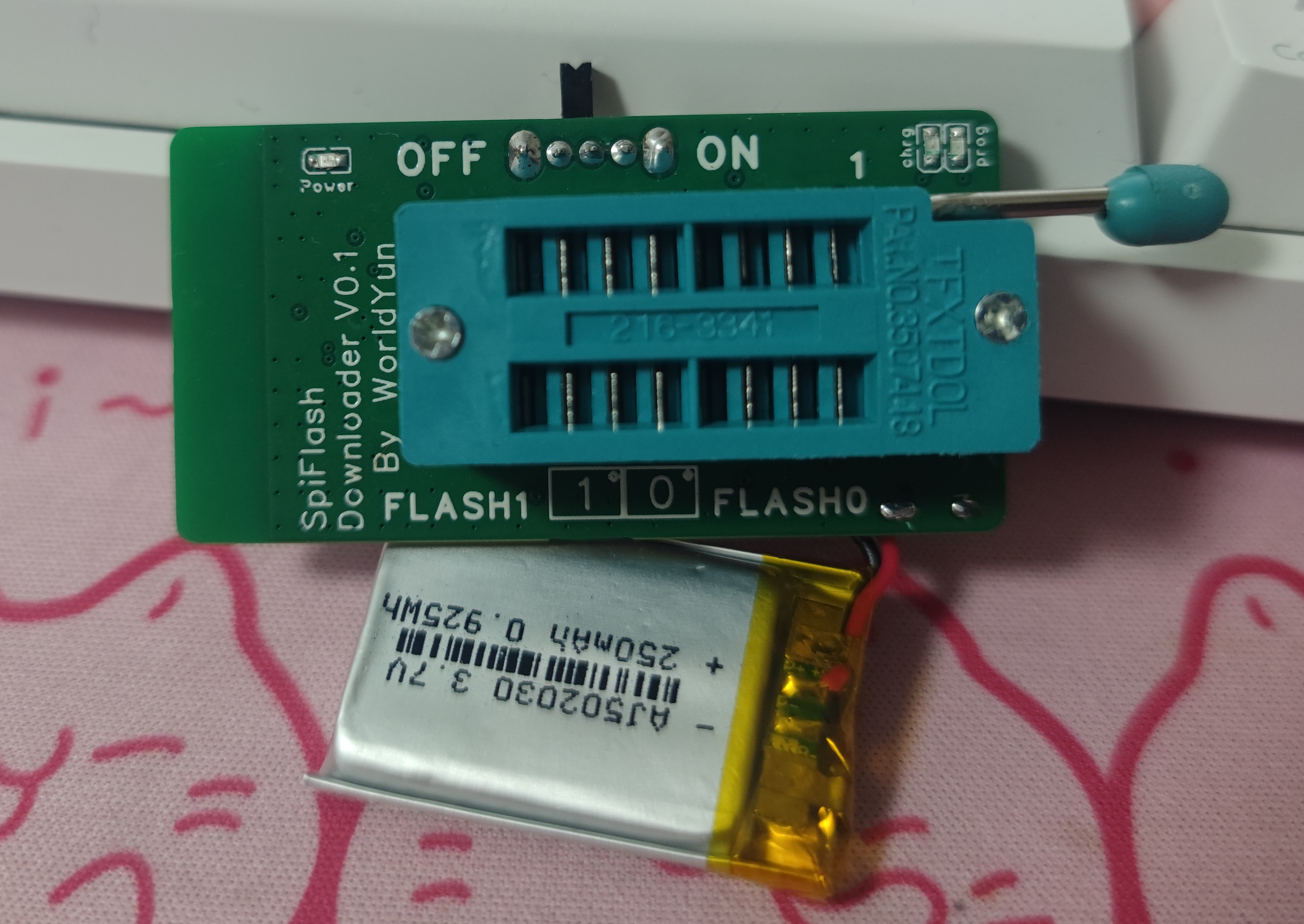
Unlike traditional USB-to-SPI programmers like the CH341A, this programmer requires no data cable connection, has a built-in battery, and transmits data via LAN. The SPI master is an ESP32-S3/C3, not a PC host computer, with an adjustable SPI frequency up to 80MHz. It features dual Flash slots for simultaneous operation and can connect to multiple programmers simultaneously. In actual testing, reading from an 8MB Flash chip took 7 seconds, and writing took 24 seconds. Read and write times are related to the wireless LAN environment; severe 2.4G WiFi interference will increase the time.
Currently, the S3, C3, and C3-DIP versions have all been verified and are safe for PCB fabrication. Cost: S3 > C3 > C3-DIP. A rough estimate of the personal replication cost for the DIP version is around ten yuan (provided you have a 0402 resistor-capacitor package). Before replication, please carefully read the following precautions: 1. Please use the BOM in the attachment. 2. The flash0 slot for the S3 and C3 versions is a 5x6 surface-mount eSIM, which will be explained in detail below. 3. When fabricating C3 and C3-DIP versions, please use JLC04161H-7628 impedance, with impedance control set to 20%.
Regarding the flash0 base for S3 and C3 versions, I have only found one seller on major online shopping platforms, priced at 0.55 RMB per piece, minimum order of 10 pieces, with shipping around 15 RMB. One pin of the base needs to be bent. There are other alternatives, priced at 19 RMB per piece, minimum order of 1 piece, free shipping, requiring modification of the PCB file. To avoid advertising, I am not providing purchase links; please find them yourself if needed. Due to the two flash base options, the cost of small-scale personal replication of the S3 and C3 versions is not low, with the C3 version approximately 27 RMB more expensive than the C3-DIP version. For mass production, the cost is 3 RMB more expensive than the C3-DIP version. The S3 version uses the S3 module, making it approximately 12 RMB more expensive than the C3 version. The C3-DIP version uses common DIP clips, offering low cost and high stability. Therefore, unless you specifically need S3 or C3 versions that allow direct programming of WSON and TSOP packaged flash chips without an adapter board, we recommend replicating the C3-DIP version. Data
reading demonstration: [Image of
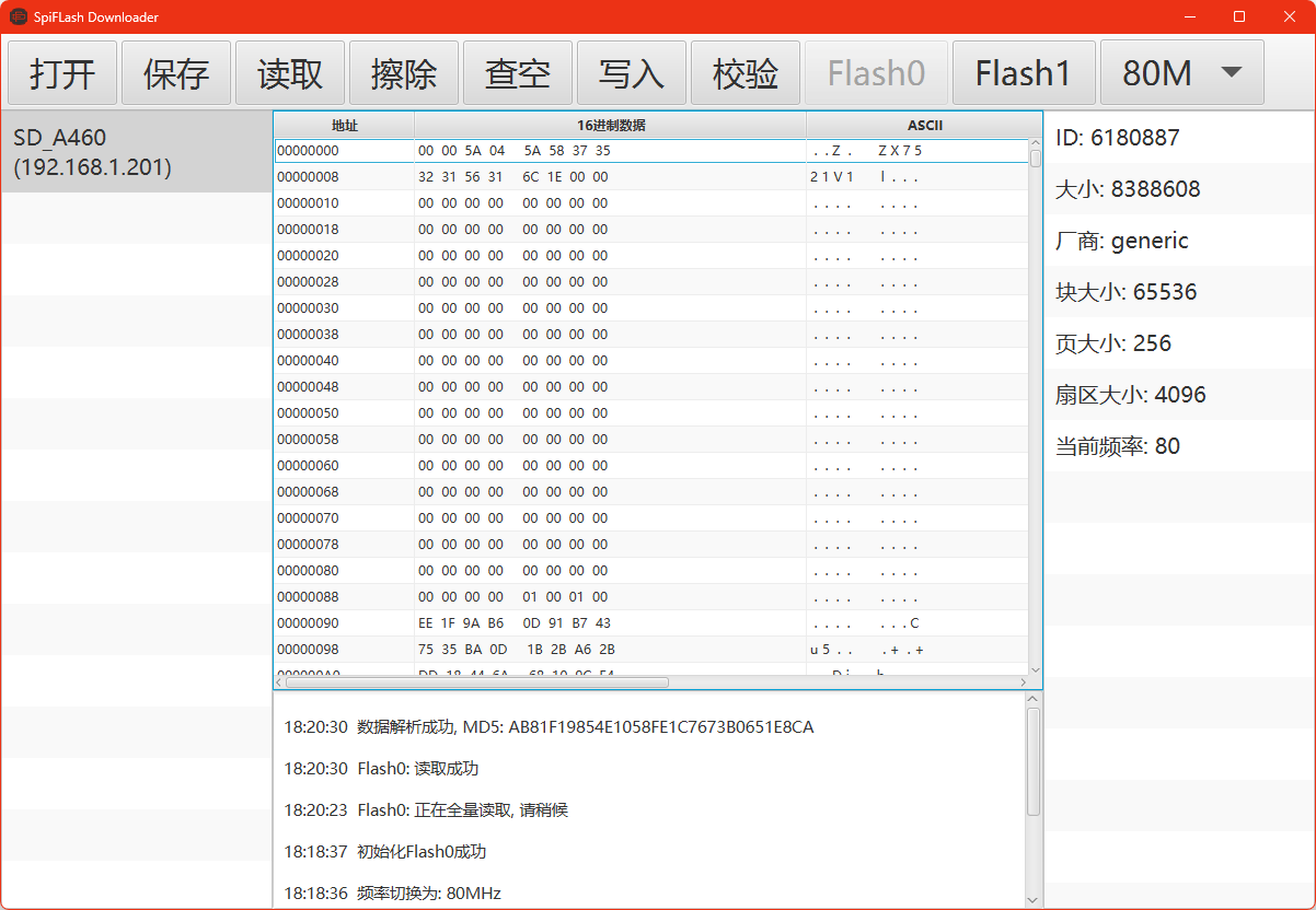
physical product] [Image of C3 version]


SFD-ESP32-C3-B.stl
SFD-ESP32-C3-T.stl
SpiFlashDownloaderSetup.exe
SFD-ESP32-C3-DIP-T.stl
SFD-ESP32-C3-DIP-B.stl
BOM_ESP32-S3-C3.xlsx
BOM_ESP32-S3-C3-DIP.xlsx
flash_download_tool_3.9.5.zip
PDF_SPI nor Flash Wireless High-Speed Programmer ESP32-S3-C3.zip
Altium_SPI nor Flash Wireless High-Speed Programmer ESP32-S3_C3.zip
PADS_SPI nor Flash Wireless High-Speed Programmer ESP32-S3_C3.zip
BOM_SPI nor Flash Wireless High-Speed Programmer ESP32-S3_C3.xlsx
95127
Van Gogh - Starry Night Light Painting
Based on the open-source Starry Sky PCB, a simple circuit is used to replicate and upgrade it into a light painting.
Under the night sky, romance surges like a tide, with twinkling stars reflecting each other, dazzling and profound, mysterious and romantic.
Based on the open-source starry sky PCB, this project replicates and upgrades it into a light painting using a simple circuit.
The original open-source starry sky PCB project link is: https://oshwhub.com/sytnocui/star-pcb-drawing.
The images show a yellow and blue starry sky both on. The
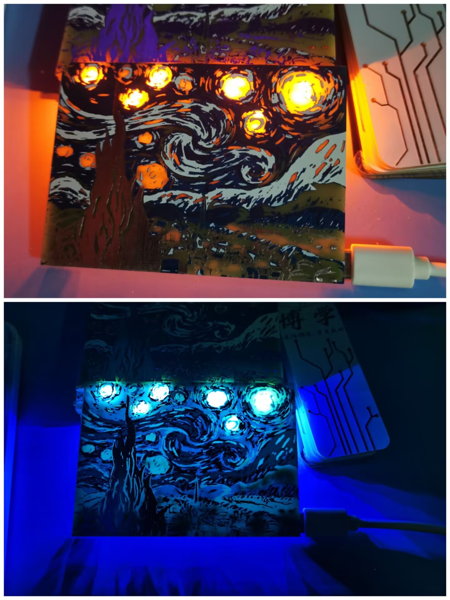
light painting features a touch switch and stepless dimming.
The light painting can be selected to be constantly lit or flashing via a toggle switch on the back. In flashing mode, stepless dimming and on/off control are also available. See the attached video link for the effect.
The effect would be even better if a corresponding 3D model could be created to block the light.
Constant light effect image.jpg
Blue starry sky twinkling effect video.mp4
Yellow starry sky twinkling effect video.mp4
PDF_Van Gogh - Starry Night Light Painting.zip
Altium_Van Gogh-Twinkle Starry Night Light Painting.zip
PADS_Van Gogh - Twinkling Starry Night Light Painting.zip
BOM_Van Gogh - Twinkling Starry Night Light Painting.xlsx
95128
electronic


 京公网安备 11010802033920号

 CY39200Z388-233NTI


