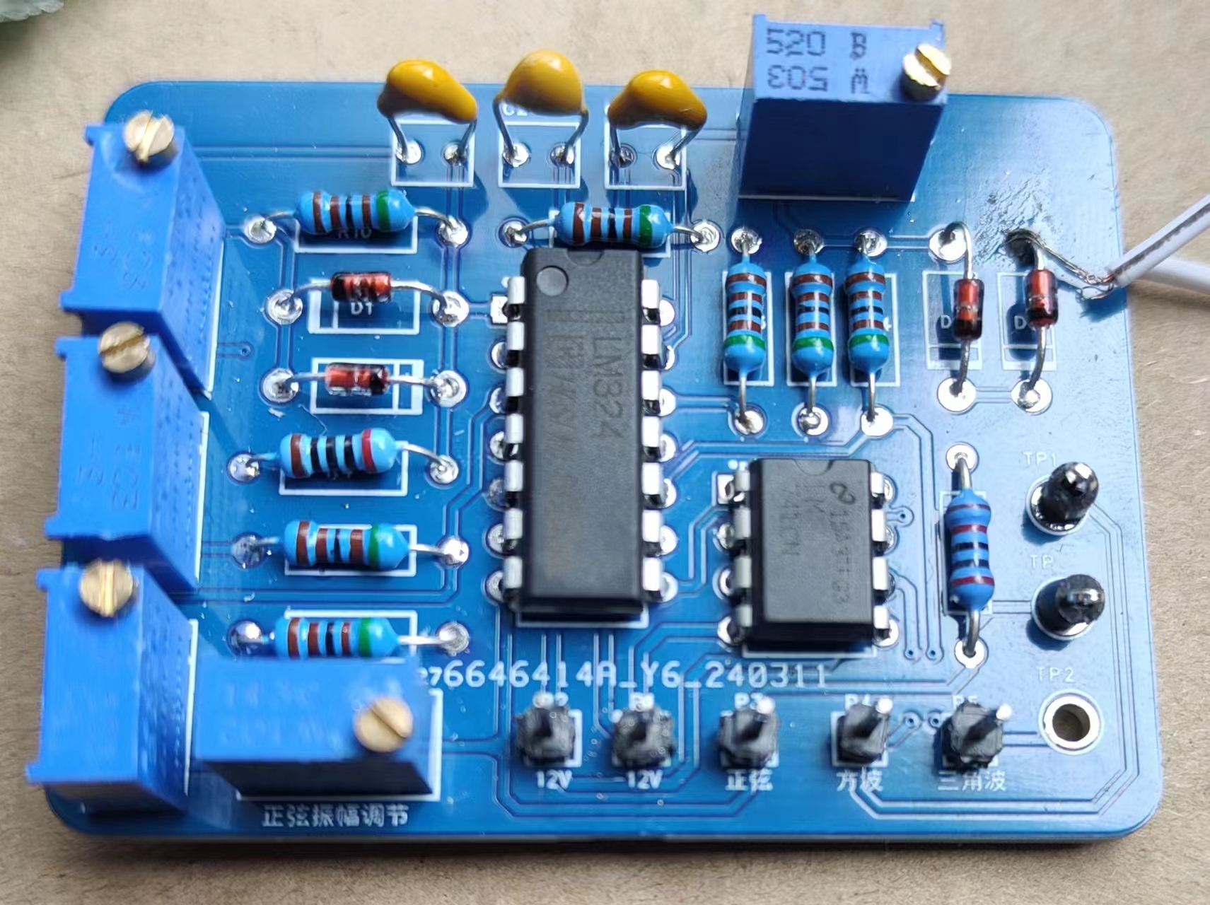
Principle: The sine generator is connected to an inverting amplifier, which can control potentiometer R7 to adjust the amplitude; its output is connected to the input of a voltage comparator, which can directly obtain a square wave signal, but the magnitude cannot be adjusted; the triangular wave signal is achieved by an independent integrating circuit (only the period can be adjusted).
Operating conditions: input voltage ±12V, and a reference ground.
PDF_SignalGenerator.zip
Altium_signal_generator.zip
PADS_SignalGenerator.zip
BOM_SignalGenerator.xlsx
95246
Laptop WWAN to USB
The laptop has a built-in 4G/5G network card to USB adapter for use as a built-in mouse receiver.
Function Description:
This laptop has a built-in 4G/5G network card to USB adapter for use with a built-in mouse receiver.
Precautions:
1. Pay attention to the soldering height of the USB female connector to avoid interference with the motherboard.
2. It uses 3.3V power supply; some receivers may not work properly. Testing showed that the Logitech Unifying receiver works normally with 3.3V, but the Bolt receiver is not recognized with 3.3V.
3. Some motherboards have unsoldered components, resulting in no 3.3V voltage output; jumper wires are required for power supply. Testing showed that the Fujitsu U939 works directly, but the Hasee K670DG4D1 has no power supply.
0.8mm
thick immersion gold plate, hand-polished and chamfered.
Revision Notes:
None.
Attachments:
A simple casing was made for easy fixation. Acknowledgements:
The
design process referenced the schematic diagram of the LTE peripherals in the Hasee K670DG4D1 (Blue Sky W650KKKJ1).
NGFF_Shell.stl
Gerber_NGFF_BK_2_USB.zip
PDF_Laptop WWAN to USB Adapter.zip
Altium_Laptop WWAN to USB Adapter.zip
PADS_Laptop WWAN to USB Adapter.zip
BOM_Laptop WWAN to USB Adapter.xlsx
95247
Bluetooth steering wheel hub: TiHUBv2
Bluetooth steering wheel hub
Features I hope everyone can improve:
Add dual-sided LEDs to each dual-sided button, single color is fine, dim, possibly driven by a MOSFET from the battery.
Add a side rotary encoder near the thumb.
Replace the encoder on the lower right side with a rotary band switch for switching modes (may need to increase the number of channels through different resistance values or shift registers).
Change one of the buttons to a seven-way joystick.
Add a battery level display (detecting the current reserved space for surface-mount resistors), which can be used in conjunction with the first LED flashing to remind the user.
I welcome suggestions for other new features to improve the user experience.
If these features are usable, I will merge them into the main branch. Let's work together to promote the progress of the open-source community and the simulator. Thank you!
Manual: TiHubV2 User Manual + BOM (qq.com)
Introduction Video:
TiHub v2 Bluetooth Wireless HUB_Bilibili_bilibili
Donations welcome:

The main features of the new steering wheel hub :
First, in terms of design, it has changed from one large board to two small boards connected in opposite directions, and the size of the boards has been just reduced to 10x10 cm, making it easier to prototype with JLCPCB.
Secondly, the main controller has been changed from ESP32 to NRF52840, which significantly reduces power consumption and greatly enhances battery life, turning the previous two or three days of battery life into almost unlimited battery life.
Thirdly, the previous mechanical keyboard switches have been replaced with simple 12x12 buttons with button caps, which feel quite good and look very professional after applying stickers.
Fourthly, the shift paddles that previously required wire connections have been replaced with onboard connections, making the assembly process much easier.
Currently, the cost of this set is very low, and since it uses pre-built modules, everyone can solder them themselves. Like the previous version, all the code and 3D models will be open source. Friends who are interested can make one and try it out, or I will also release the pre-built kit later.
PDF_Bluetooth Steering Wheel Hub: TiHUBv2.zip
Altium Bluetooth Steering Wheel Hub: TiHUBv2.zip
PADS Bluetooth Steering Wheel Hub: TiHUBv2.zip
BOM_Bluetooth Steering Wheel Hub: TiHUBv2.xlsx
95248
Mini Easy Digital Oscilloscope
A simple digital oscilloscope based on the GD32E230C8T6, with a small size.
I. Introduction
• A simple digital oscilloscope based on GD32E230C8T6. Dimensions: 7.5*4.5*1.4cm (height is estimated, excluding the rotary encoder).
The schematic is mainly based on the training camp, with the screen design referenced from a Taobao seller (HeZhou also has schematics).
The shape is inspired by @qaxslk's sandwich structure (not yet board-made)
. The firmware currently uses @eos911's large-screen firmware (until the Clion environment is set up)
. Compared to the training camp version, all components have been swapped for surface-mount packages, buttons have been changed to side buttons, PWM is led out via copper pillars, GD32 chips are used directly, the screen uses a wire-bonded design, the BNC interface has been changed to an MMCX interface, and some resistor values have been modified (see details below) .
Ideal cost: Rotary encoder 1.68, MMCX 2, 1.8 TFT screen 6.6, TLP72I 0.22, LM393 0.18, XL7660 0.6, GD32E230C8T6 1.05, crystal oscillator 0.44, AMS1117-3.3 0.2, others are negligible (actual cost is higher)
. And it's a pity I missed the event... II. Specific modifications
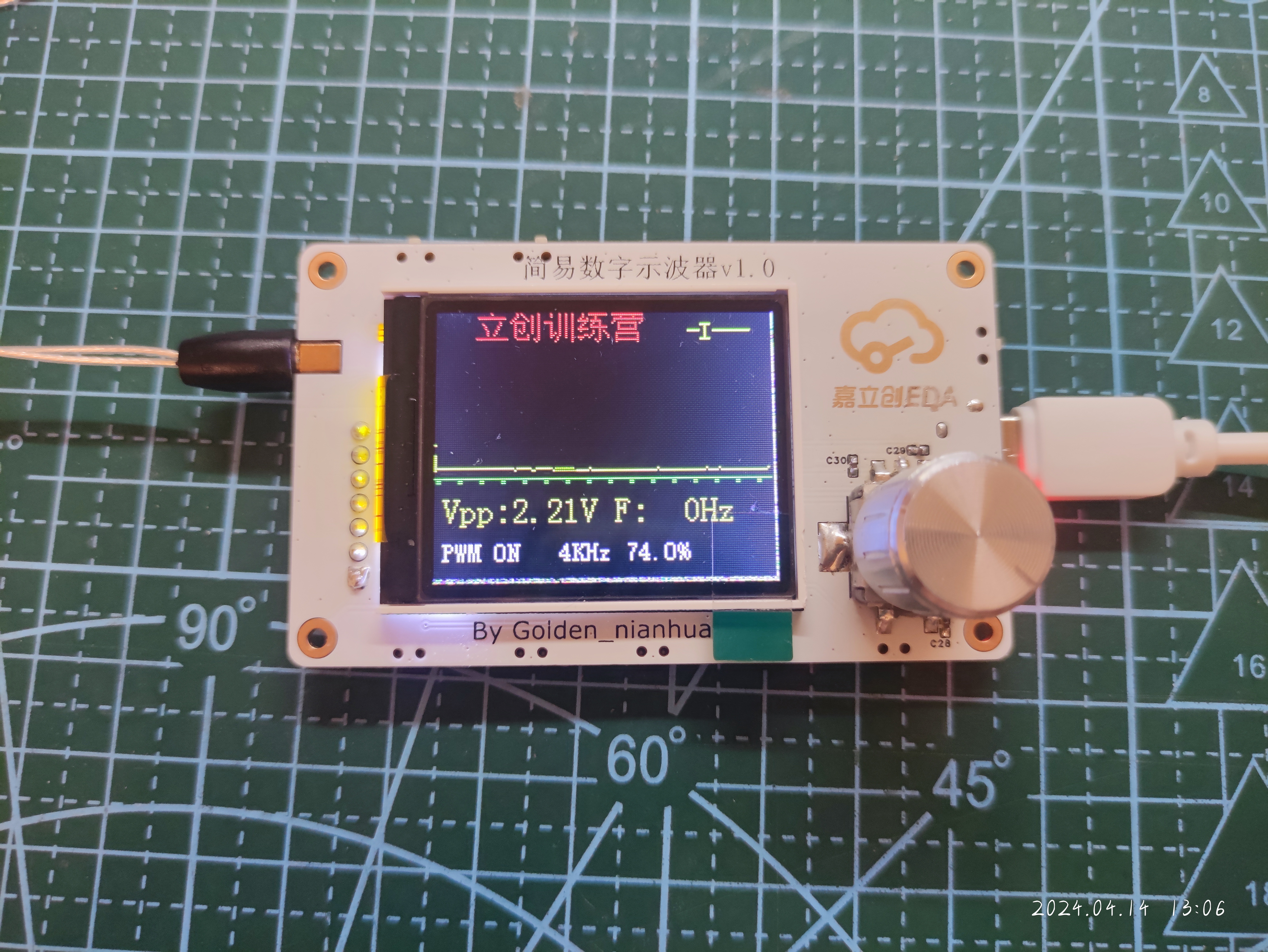
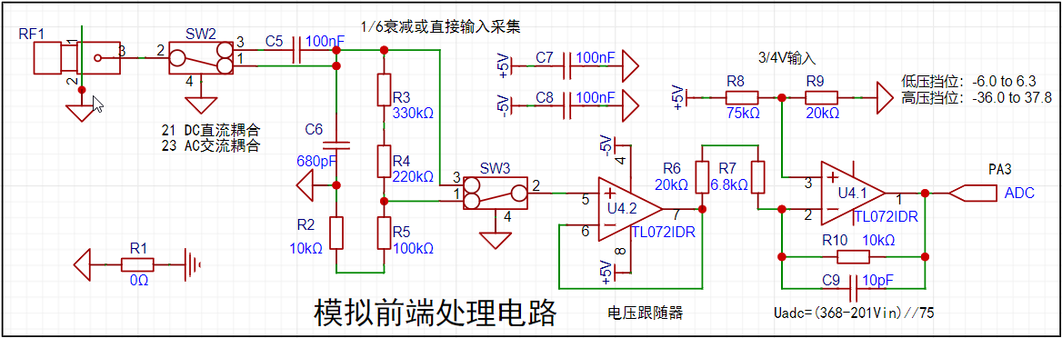
to the simulated front-end processing circuit are shown in the figure. Only calculations were performed, not simulations. III. Issues : • The rotary encoder's rotation direction is reversed. It seems easier to modify the firmware or the wiring later. • KEY1 and KEY2 are reversed (I didn't even notice the reversed order while routing the wiring...). • The screen driver seems incompatible, shifting slightly to the upper left. • Direct copper connection to the GND pads causes too much heat dissipation, hindering desoldering. • It seems better to leave the two corners of the 3.3V power supply section on the screen pads unconnected.
Oscilloscope v1.0 Verification.mp4
PDF_mini Simple Digital Oscilloscope.zip
Altium_mini Simple Digital Oscilloscope.zip
PADS_mini Simple Digital Oscilloscope.zip
BOM_mini Simple Digital Oscilloscope.xlsx
95253
TP4333 power bank
Power bank based on TP4333
The PCB board is designed based on the 18650 battery box from Taobao. It can be directly glued on with hot glue. The input and output are 1A, which is only for emergency use. I didn't add the button lights on the board; you can adjust them yourself.
PDF_TP4333 Power Bank.zip
Altium_TP4333 power bank.zip
PADS_TP4333 power bank.zip
BOM_TP4333 Power Bank.xlsx
95254
Industrial vacuum cleaner main control
Control of industrial vacuum cleaners
The design of a vacuum cleaner control system is a complex and precise engineering project, integrating multiple key modules and technologies to ensure system stability and reliability while achieving vacuum cleaner control functions. The core components of this system include a control module, solenoid valve control, comparators, optocoupler SCR drivers, optocoupler zero-crossing detection, and AC current rectification, each playing a crucial role.
First, let's look at the control module. This module is the brain of the entire system, responsible for coordinating and controlling the operation of various components. It controls the system through two input paths. The first path involves AC power being stepped down by a transformer, then rectified to output a stable 12V DC voltage, which is then output as 5V DC via an LDO to supply the microcontroller, comparator, and optocoupler. The second path involves AC power being output as DC via a current transformer and rectifier bridge, compared by a comparator, and outputting high/low level signals based on the relationship between the input voltage and the reference voltage. These signals are then input to the microcontroller for processing.
The microcontroller plays a critical role in this system, with two I/O ports for selecting automatic and manual modes. Switching between modes is achieved by connecting a single-pole double-throw switch to ground. In automatic mode, when the microcontroller receives a high-level signal from the comparator, it outputs a low-level signal to control the optocoupler, causing the motor to start working. If the microcontroller does not receive a signal from the comparator, it will detect a signal through a sensor, and the connected diode will also conduct, triggering the optocoupler and motor to work.
Regarding the adjustment of the motor speed and the solenoid valve's vibration frequency, the system utilizes the voltage divider principle of two resistors; the microcontroller can switch and adjust based on the voltage signal received from the I/O port. This achieves precise control of the vacuum cleaner's operating state, thereby improving its performance and efficiency.
In addition to the above functions, the system also includes an optocoupler connection to the solenoid valve for control. By controlling the optocoupler's conduction, the solenoid valve's operating state can be precisely controlled, enabling comprehensive control and management of all components of the vacuum cleaner.
The design of the vacuum cleaner control system not only involves various advanced technologies and modules but also requires careful design and debugging of the collaborative relationships between various components to ensure the system's stability, reliability, and efficiency. This complexity and precision in system design provides a solid foundation for improving vacuum cleaner performance and lays an important foundation for the future development of vacuum cleaner control technology.
PDF_Industrial Vacuum Cleaner Main Control Unit.zip
Altium_Industrial Vacuum Cleaner Main Controller.zip
PADS_Industrial Vacuum Cleaner Main Controller.zip
BOM_Industrial Vacuum Cleaner Main Control File.xlsx
95255
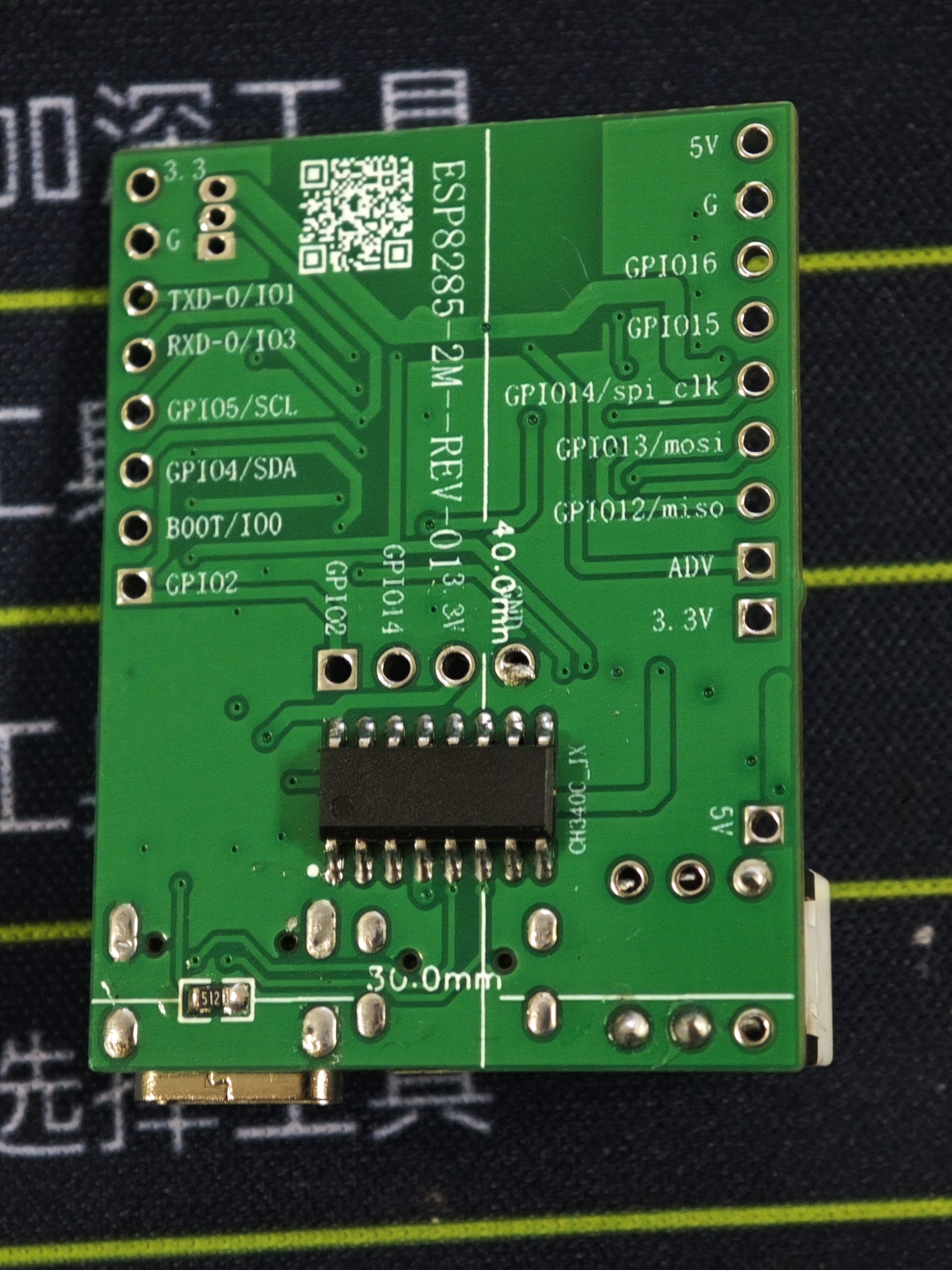
ESP8285 development board Type-C automatic download of version 340c
The ESP8285 module development board features an onboard 340 serial port for downloading and supports both Android and Type-C interfaces.
The buttons are a bit big. Oh well, I accidentally added an extra zero to the buttons last time I bought them. I'll just use them gradually. They're all
the two common types of resistors: one 10k and one 4.7k. Of course, you could use all 10k resistors.
I don't have that many components on hand, so I'll just make do with what I have.
The board design isn't very good, so I'm just showing it off.

Blink_LED-1.ino
PDF_ESP8285 Development Board Type-C Automatic Download Version 340c.zip
Altium_ESP8285 development board Type-C automatic download of version 340c.zip
PADS_ESP8285 development board Type-C automatic download of version 340c.zip
BOM_ESP8285 development board Type-C automatic download of version 340c.xlsx
95256
ESP smart switch
Switch based on ESP8266 and magnetic latching relay
Project Objective:
In today's booming smart home market, some older homes, or even rented apartments, face challenges in installing smart home systems due to wiring or other reasons. This project aims to create a small module that allows users with some DIY skills to experience low-latency smart control without altering existing switches and wiring.
Hardware:
ESP12 + magnetic latching relay, along with a DH11 temperature and humidity module and a photoresistor.
Software:
ESPHOME programming is used, requiring only simple configuration and offering convenient online OTA updates.
Results:
This module enables smart control of lights without altering existing switch wiring, maintaining the original switch functionality. It also caters to those unfamiliar with smart home systems, providing a seamless transition.
Note:
The PCB DRC may report pads being too close to the slot. This is intentional for easier soldering. This board has been verified and functions correctly.
Because my ESPHOME server is not on the same network segment, I used MQTT to connect to Home Assistant; using ESPHOME directly would be more convenient.
esp12.yaml
PDF_esp Smart Switch.zip
Altium_esp smart switch.zip
PADS_esp smart switch.zip
BOM_esp Smart Switch.xlsx
95257
ESP8266 Single-channel motor/servo control board
The board supports 5-32V power supply; the PWM power output voltage depends on the battery power supply voltage. It can be controlled via Wi-Fi hotspot.
The board supports 5-32V power supply; the PWM power output voltage depends on the battery power supply voltage. It can be controlled via Wi-Fi hotspot.
PDF_ESP8266 Single-channel motor-servo control board.zip
Altium_ESP8266 Single-channel Motor_Servo Control Board.zip
PADS_ESP8266 Single-channel Motor/Servo Control Board.zip
BOM_ESP8266 Single-channel motor_servo control board.xlsx
95258
Studio 32 Practice Board
This is a learning practice board for new students in the mobile robotics studio. Most of the board uses 0603 surface mount technology for soldering practice. The cost of one board is approximately forty yuan.
This is a practice board designed for first-year students in the studio. It allows them to practice soldering and learn STM32, and is relatively inexpensive considering its cost-effectiveness.
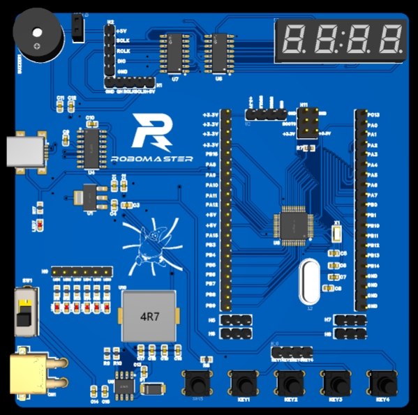
The board is a double-layer board, with most components in 0603 surface mount packages, making it suitable for beginners who want to learn soldering. The XT-30 module in the lower left corner can be removed if the 12V requirement is not needed. It can implement everyday functions such as a buzzer, LED, digital display, and buttons. All pins are brought out for various expansion capabilities. The board uses SWD/USB download and supports 5V/3.3V/12V power supply, making it easy for beginners to learn.
PDF_Studio 32 Practice Board.zip
Altium_Studio32PracticeBoard.zip
PADS_Studio 32 Practice Board.zip
BOM_Studio 32 Practice Board.xlsx
95259
electronic


 京公网安备 11010802033920号

 X40411V8-A


