is to create a thermal printer driver board based on an ESP32 wireless module, capable of printing images and text.
Stepper motor driver.
below; Power-on and driver download completed; Photo printing results as shown below .
This is a simple current and voltage meter based on the CW32F030C8T6 microcontroller, specifically the LCSC Diwenxing development board.
This is a simple current and voltage meter based on the CW32F030C8T6 microcontroller, specifically the LCSC Diwenxing development board. It can measure parameters such as voltage, current, and power. This
article will briefly introduce the design ideas of both the hardware and software.
Software code open source link .
Hardware
1. Voltage Sampling Circuit
Since it is a simple current and voltage meter, it must have voltage and current sampling circuits, as shown in the figure.

You can see that there are two voltage ranges. Here, we take the 0~30V range as an example.
V+ is the voltage input terminal. After being divided by resistors R9 and R10, it is filtered by C23 and clamped by D2, and then output to the CW32's ADC channel 11. Assuming the CW32's ADC reference voltage is 1.5V, we can calculate:
1.5/10K = Vmax / (10K + 220K), that is, Vmax = 1.5 * 23 = 34.5V is the maximum voltage.
Because resistors have a precision range, a 220K resistor may not actually be 220K; it could be 219K, 221K, etc., leading to potentially inaccurate voltage data. Therefore, voltage measurement calibration is necessary. A circuit for analog voltage measurement is designed:

by using adjustable resistors to divide the input voltage, the desired voltage value can be adjusted for subsequent software calibration.
2. The current sampling circuit
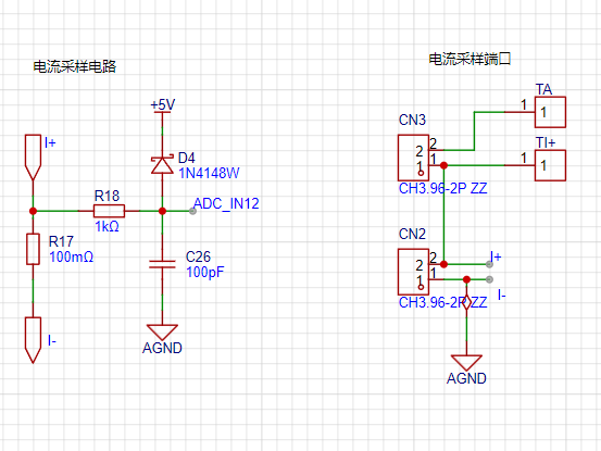
is shown in the figure. Based on the physics learned in junior high school, U=IR. Given U and R, I can be easily derived. The principle of current sampling is to measure the voltage across the sampling resistor to obtain the current flowing through it.
In the figure, the current flows from I+ through the sampling resistor R17 and then to I-. The ADC ground is connected to I-, so only the voltage across I+ needs to be sampled to obtain the current data.
Of course, during debugging and calibration, it is difficult to obtain the desired current flowing through R17, but obtaining the required voltage is relatively simple. Therefore, a circuit for simulating current acquisition was also designed:
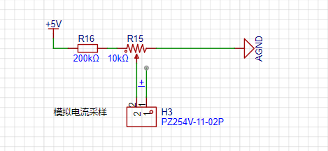
we first do not solder R17, and obtain the corresponding voltage value by adjusting the value of R15, thereby simulating the corresponding current.
3. Power Supply Circuit:

Since the LDO on the development board does not have a very high withstand voltage, in order to work properly, we need a higher withstand voltage LDO to output a 5V voltage to the development board and some peripheral circuits.
In front of the LDO, there is a reverse connection protection circuit composed of D1, and a low-pass filter circuit composed of C18, C17, C20, C21, and U3. This circuit can filter out some high-frequency interference and increase the stability of the circuit. U3 is actually a resistor.
4. Control Circuit:

The control circuit mainly consists of a human-machine interaction circuit composed of 3 buttons and a 0.96-inch OLED display screen.
5. Other
circuits:
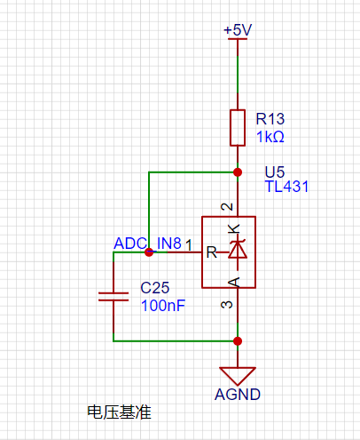
A voltage reference circuit, which can provide an additional voltage reference input to the ADC.
The software
primarily showcases the code for key functionalities; the actual code will be open-sourced on Gitee and GitHub.
Directory structure:
├─.cmsis
│ └─include
├─.eide
├─.pack
│ └─WHXY
│ └─CW32F030_DFP.1.0.5
│ ├─Device
│ │ ├─Include
│ │ └─Source
│ │
└─ARM │ ├─Flash
│
└─SVD ├─.vscode
├─APP
│ └─ui
├─Board
├─BSP
│ ├─key
│ ├─log
│ ├─oled
│ ├─u8g2
│ └─uart
├─build
│ └─Project
│ └─.obj
│ ├─APP
│ │ └─ui
│ ├─Board
│ ├─BSP
│ │ ├─key
│ │ ├─log
│ │ ├─oled
│ │ ├─u8g2
│ │ └─uart
│ ├─Libraries
│ │ └─src
│ └─Module
│ ├─adc
│ ├─flash
│ ├─oled
│ ├─timer
│ └─u8g2
├─Libraries
│ ├─inc
│ └─src
├─Module
│ ├─adc
│ ├─flash
│ └─timer
└─Project
└─MDK
└─RTE
├─Device
│ └─CW32F030C8
├─_Project
└─_Target_1
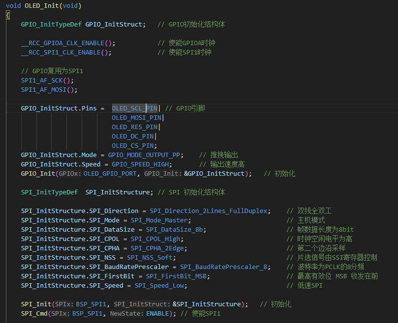
1. The display section
is as described above. The voltage and current data are displayed using a 0.96-inch OLED screen, so an OLED screen driver needs to be written. Here, we refer to the code from Zhongjingyuan. The GPIO pins connected to the OLED need to be initialized:
Because the u8g2 graphics library is used, the graphics library code also needs to be ported.

After porting, code needs to be written to display voltage and current data, voltage calibration, and current calibration interfaces:
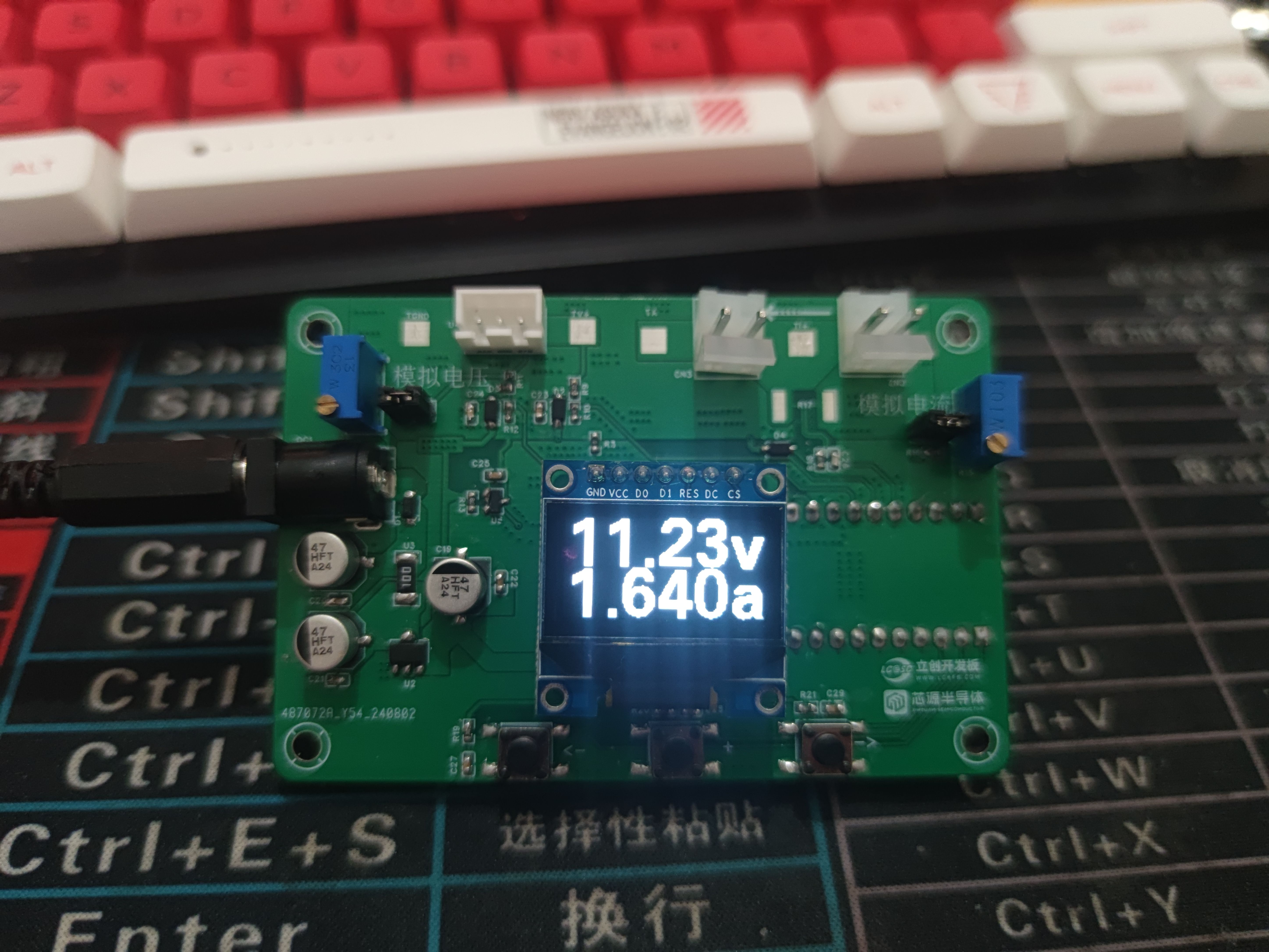
void UI_main(u8g2_t *u8g2) // Main interface, displaying voltage and current information
{
u8g2_SetFont(u8g2, u8g2_font_fub30_tf);
Vol_ADC = mean_value_filter(VLotage_buff, ADC_SAMPLE_SIZE);
Cur_ADC = mean_value_filter(Current_buff, ADC_SAMPLE_SIZE);
if (Vol_ADC > X05)
{
Vol_Real = (float32_t)((Vol_ADC - X05) * K + Y05);
}
else
{
Vol_Real = (float32_t)(Vol_ADC * K);
}
if (Cur_ADC > IX05)
{
Cur_Real = (float32_t)(((Cur_ADC - IX05) * KI + IY05) / 100);
}
else
{
Cur_Real = (float32_t)(Cur_ADC * KI / 100);
}
u8g2_FirstPage(u8g2);
do
{
sprintf(buff, "%.2fv", Vol_Real);
u8g2_DrawStr(u8g2, 0, 31, buff);
sprintf(buff, "%.3fa", Cur_Real);
u8g2_DrawStr(u8g2, 0, 63, buff);
} while (u8g2_NextPage(u8g2));
}
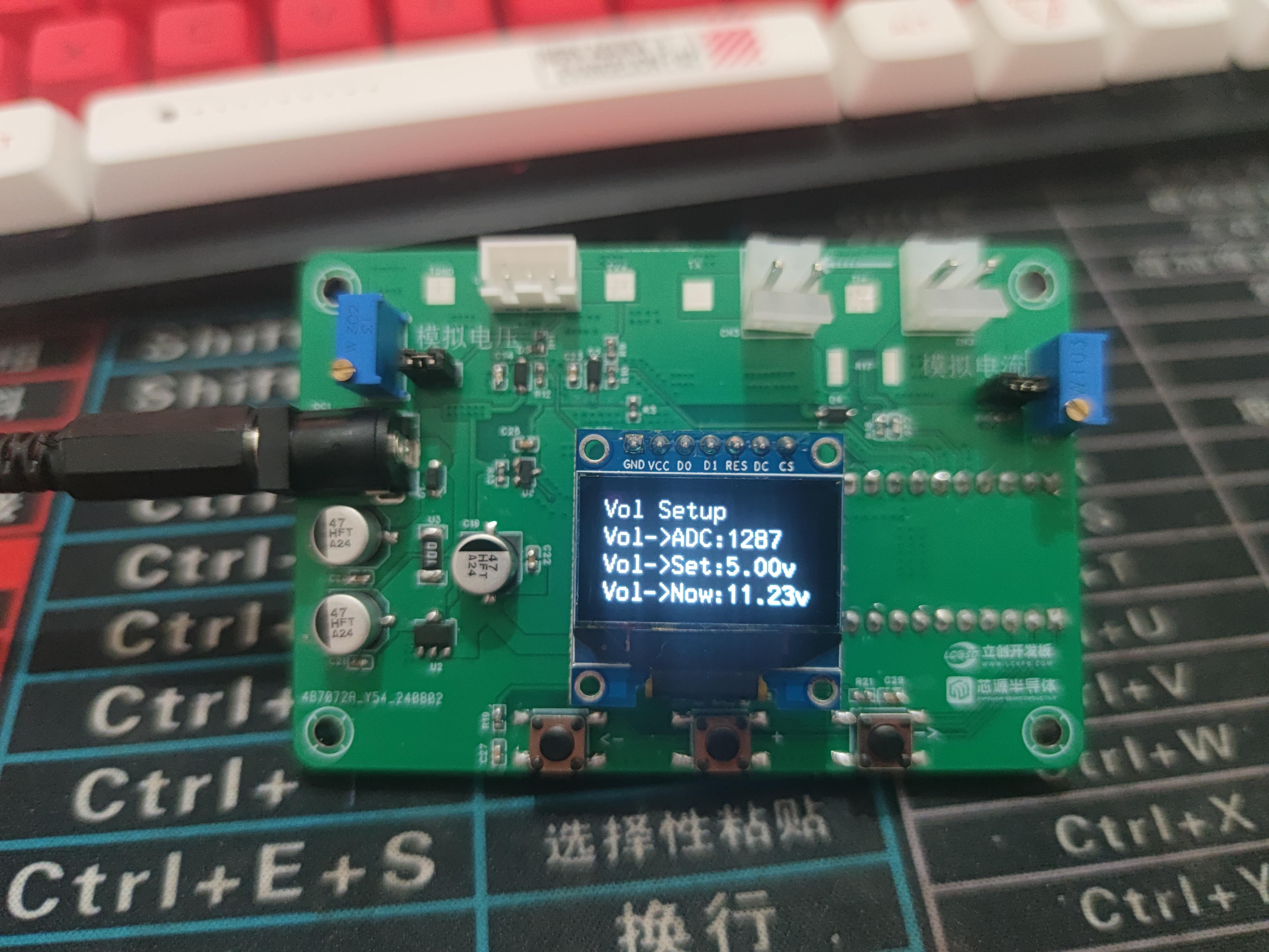
void UI_SetVOl(u8g2_t *u8g2) //Voltage calibration interface
{
u8g2_SetFont(u8g2, u8g2_font_t0_16_tf);
Vol_ADC = mean_value_filter(VLotage_buff, ADC_SAMPLE_SIZE);
if (Vol_ADC > X05)
{
Vol_Real = (float32_t)((Vol_ADC - X05) * K + Y05);
}
else
{
Vol_Real = (float32_t)(Vol_ADC * K);
}
u8g2_FirstPage(u8g2);
do
{
sprintf(buff, "Vol Setup");
u8g2_DrawStr(u8g2, 0, 15, buff);
sprintf(buff, "Vol->ADC:%d", Vol_ADC);
u8g2_DrawStr(u8g2, 0, 31, buff);
switch (Vol_List)
{
case CA_Y05:
sprintf(buff, "Vol->Set:%.2fv", (float32_t)Y05);
break;
case CA_Y15:
sprintf(buff, "Vol->Set:%.2fv", (float32_t)Y15);
break;
default:
break;
}
u8g2_DrawStr(u8g2, 0, 47, buff);
sprintf(buff, "Vol->Now:%.2fv", Vol_Real);
u8g2_DrawStr(u8g2, 0, 63, buff);
} while (u8g2_NextPage(u8g2));
}
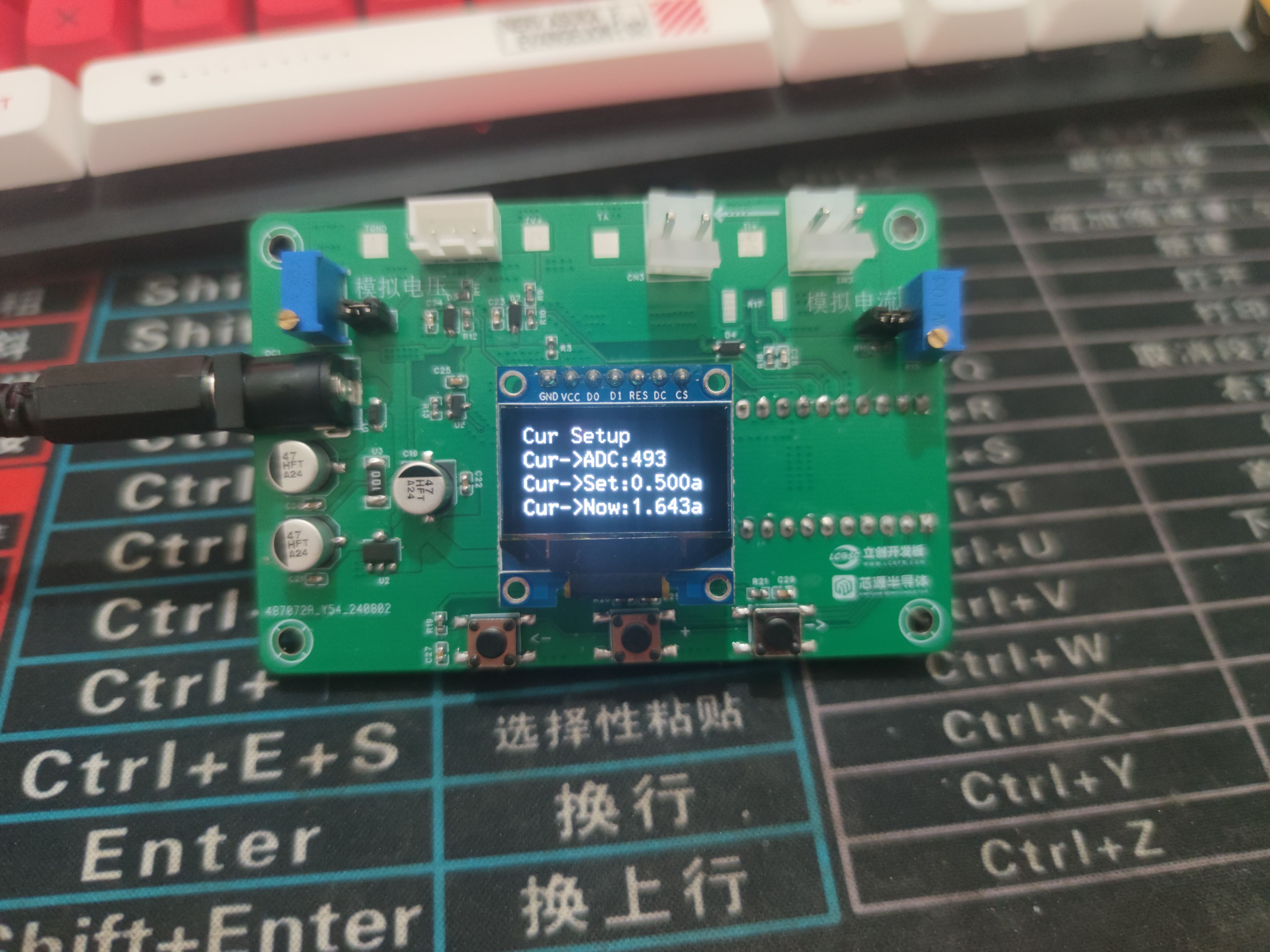
void UI_SetCurr(u8g2_t *u8g2) //Current calibration interface
{
u8g2_SetFont(u8g2, u8g2_font_t0_16_tf);
Cur_ADC = mean_value_filter(Current_buff, ADC_SAMPLE_SIZE);
if (Cur_ADC > IX05)
{
Cur_Real = (float32_t)(((Cur_ADC - IX05) * KI + IY05) / 100);
}
else
{
Cur_Real = (float32_t)(Cur_ADC * KI / 100);
}
u8g2_FirstPage(u8g2);
do
{
sprintf(buff, "Cur Setup");
u8g2_DrawStr(u8g2, 0, 15, buff);
sprintf(buff, "Cur->ADC:%d", Cur_ADC);
u8g2_DrawStr(u8g2, 0, 31, buff);
switch (Cur_List)
{
case CA_Y05:
sprintf(buff, "Cur->Set:%.3fa", (float32_t)IY05 / 100);
break;
case CA_Y15:
sprintf(buff, "Cur->Set:%.3fa", (float32_t)IY15 / 100);
break;
default:
break;
}
u8g2_DrawStr(u8g2, 0, 47, buff);
sprintf(buff, "Cur->Now:%.3fa", Cur_Real);
u8g2_DrawStr(u8g2, 0, 63, buff);
} while (u8g2_NextPage(u8g2));
}
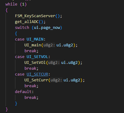
In the main function, different interfaces are displayed according to the interface variables:
2. Button control part
Because there is bouncing during the button press, it will cause errors in the MCU reading the pin level, so filtering is required. In the hardware design, a capacitor is added as a hardware filter for each button. In the software, a timer and finite state machine algorithm are used to implement button filtering.
First, configure the timer. Here, we configure basic timer 1 as a 1ms interrupt:
`void BTIME1_InitFor1ms()
{
__RCC_BTIM_CLK_ENABLE();
__disable_irq();
NVIC_EnableIRQ(BTIM1_IRQn);
__enable_irq();
BTIM_TimeBaseInitTypeDef BTIM_TimeBaseInitStruct = {
.BTIM_Mode = BTIM_Mode_TIMER,
.BTIM_OPMode = BTIM_OPMode_Repetitive,
.BTIM_Period = 8192,
.BTIM_Prescaler = BTIM_PRS_DIV8};
BTIM_TimeBaseInit(CW_BTIM1, &BTIM_TimeBaseInitStruct);
// Enable BTIM1's overflow interrupt
BTIM_ITConfig(CW_BTIM1, BTIM_IT_OV, ENABLE);
// Start timer BTIM1`
BTIM_Cmd(CW_BTIM1, ENABLE);
}
Then set the key scan flag to 1 every 10ms.
uint16_t t;
extern uint8_t adc_en;
void BTIM1_IRQHandler(void)
{
// Check if it's an overflow interrupt
if (BTIM_GetITStatus(CW_BTIM1, BTIM_IT_OV))
{
// Clear the overflow interrupt flag
BTIM_ClearITPendingBit(CW_BTIM1, BTIM_IT_OV);
FSM_KeyScanHeadler(1);// Heartbeat of the state machine
if(++t == 500)
{
t = 0;
adc_en = 1;
}
}
}
Then initialize the GPIO of the buttons
void KEY_Init()
{
RCC_AHBPeriphClk_Enable(RCC_AHB_PERIPH_GPIOB, ENABLE);
GPIO_InitTypeDef GPIO_InitStructure = {
.Pins = KEY1_PIN | KEY2_PIN | KEY3_PIN,
.Mode = GPIO_MODE_INPUT,
.Speed = GPIO_SPEED_HIGH};
GPIO_Init(KEY_PORT, &GPIO_InitStructure);
KEY_defconfig(KEY);
KEY[KEY_LEFT].ReadKeyValue = KEY_LeftRead;
KEY[KEY_RIGHT].ReadKeyValue = KEY_RightRead;
KEY[KEY_OK].ReadKeyValue = KEY_OkRead;
}
First, we define some key-related structures, etc.:
/// @brief Key-related
typedef enum
{
KEY_STATE_RELEASE = 0,
KEY_STATE_PRESS,
} KEY_STATE;
typedef enum
{
KEY_LEVEL_LOW = 0,
KEY_LEVEL_HIGH
} KEY_LEVEL;
typedef enum
{
KEY_EVEN_NULL = 0,
KEY_EVEN_PRESS,
KEY_EVEN_RELEASE,
KEY_EVEN_CLICK,
KEY_EVEN_REPEAT,
KEY_EVEN_LONGPRESS_STAR,
KEY_EVEN_LONGPRESS_HOLD,
} KEY_EVEN;
typedef enum KEY_LIST_t
{
KEY_LEFT = 0,
KEY_OK,
KEY_RIGHT,
KEY_COUNT // Number of keys, must be fixed, the first key enumeration must be set to 0
} KEY_LIST;
/// @brief FSM related
typedef enum
{
FSM_KEY_Up = 0, // Key release
FSM_KEY_DownShake, // Key press shake
FSM_KEY_Down, // Key press state
FSM_KEY_UpShake, // Key release shake
} FSM_State_t;
typedef enum
{
FSM_EVEN_INIT = 0,
FSM_EVEN_PRESS,
FSM_EVEN_CLICK,
FSM_EVEN_REPEATDOWN,
FSM_EVEN_LONGPRESS
} FSM_EVEN_State_t;
typedef struct
{
FSM_State_t state; // Key state
FSM_EVEN_State_t even_state;
uint8_t volatile cnt; // Timer
uint8_t volatile click_times; // Number of consecutive presses
} FSM_value_t;
typedef struct
{
KEY_LEVEL key_pressLevel;
FSM_value_t FSM_value;
KEY_STATE key_state;
void (*EvenCallBack)(KEY_EVEN, void *);
uint32_t (*ReadKeyValue)(void);
} KEY_t;
Key state machine
Because key bounce occurs during the transition between pressed and released states, we divide the key state into 4: key release state, key press bounce state, key press state, key release state
. 1. By default, the key is in the released state. We check the key every 10ms. When the level read is the level of the key being pressed, we enter the key press bounce state; otherwise, we remain in the key release state.
2. In the key press bounce state, we check the key level again (another 10ms has passed). If the key level is the level of the key being pressed, then we can confirm that the key is indeed pressed and enter the key press state.
3. Button pressed state. (Another 10ms has elapsed) Check the button level again. If it remains at the pressed level, maintain the button pressed state; otherwise, enter the button release bouncing state
. 4. Button release bouncing state. Similarly, when the button level is at the release level, enter the button release state; otherwise, return to the button pressed state.
The finite state machine
code for button state scanning is now complete as follows:
if (FSM_Scan_Count >= TICKS_INTERVAL) // Default entry time is 10ms
{
FSM_Scan_Count = 0;
for (uint8_t i = 0; i < KEY_COUNT; i++)
{
/**
* @brief This part is the button state scan
*
*/
if (KEY[i].ReadKeyValue == NULL)
continue;
switch (KEY[i].FSM_value.state)
{
case FSM_KEY_Up: // If the key is pressed, enter the key-pressed bounce state; otherwise, enter the key-released state.
if (KEY[i].ReadKeyValue() == KEY[i].key_pressLevel)
KEY[i].FSM_value.state = FSM_KEY_DownShake;
else
{
KEY[i].key_state = KEY_STATE_RELEASE;
}
break;
case FSM_KEY_DownShake: // Key-pressed bounce state. This is after one time delay. If the key is pressed,
if (KEY[i].ReadKeyValue() == KEY[i].key_pressLevel)
KEY[i].FSM_value.state = FSM_KEY_Down;
else
KEY[i].FSM_value.state = FSM_KEY_Up;
break;
case FSM_KEY_Down:
if (KEY[i].ReadKeyValue() == KEY[i].key_pressLevel)
{
KEY[i].key_state = KEY_STATE_PRESS;
}
else
KEY[i].FSM_value.state = FSM_KEY_UpShake;
break;
case FSM_KEY_UpShake:
if (KEY[i].ReadKeyValue() == KEY[i].key_pressLevel)
KEY[i].FSM_value.state = FSM_KEY_Down;
else
KEY[i].FSM_value.state = FSM_KEY_Up;
break;
default:
break;
}
The event handling part of the button is based on multibotton on GitHub.
/**
* @brief This part detects button events, such as single click, double click, etc., and calls the corresponding callback function
*
*/
switch (KEY[i].FSM_value.even_state)
{
case FSM_EVEN_INIT: // Initial state
if (KEY[i].key_state == KEY_STATE_PRESS)
{
KEY[i].FSM_value.even_state = FSM_EVEN_PRESS;
KEY[i].EvenCallBack(KEY_EVEN_PRESS, NULL); // Trigger button press event
}
else
KEY[i].FSM_value.even_state = FSM_EVEN_INIT;
break;
case FSM_EVEN_PRESS:
if (KEY[i].key_state == KEY_STATE_PRESS)
{
if (KEY[i].FSM_value.cnt++ > (200 / TICKS_INTERVAL)) // If pressed, enter long press state
{
KEY[i].FSM_value.cnt = 0;
KEY[i].FSM_value.even_state = FSM_EVEN_LONGPRESS;
KEY[i].EvenCallBack(KEY_EVEN_LONGPRESS_STAR, NULL); // Trigger long press start event
}
}
else
{
KEY[i].FSM_value.click_times++;
KEY[i].FSM_value.even_state = FSM_EVEN_CLICK; // Otherwise, enter click state
KEY[i].EvenCallBack(KEY_EVEN_RELEASE, NULL);
}
break;
case FSM_EVEN_CLICK:
if (KEY[i].key_state == KEY_STATE_PRESS)
{
KEY[i].FSM_value.cnt = 0;
KEY[i].FSM_value.even_state = FSM_EVEN_REPEATDOWN; // If pressed, enter combo state
}
else // Otherwise, trigger combo event or click event according to the condition
{
if (KEY[i].FSM_value.cnt++ >= SHORT_TICKS)
{
KEY[i].FSM_value.cnt = 0;
KEY[i].FSM_value.even_state = FSM_EVEN_INIT;
if (KEY[i].FSM_value.click_times > 1)
KEY[i].EvenCallBack(KEY_EVEN_REPEAT, (void *)&KEY[i].FSM_value.click_times);
else
KEY[i].EvenCallBack(KEY_EVEN_CLICK, NULL);
KEY[i].FSM_value.click_times = 0;
}
}
break;
case FSM_EVEN_REPEATDOWN:
if (KEY[i].key_state == KEY_STATE_PRESS)
{
if (KEY[i].FSM_value.cnt++ >= LONG_TICKS / 2)
{
KEY[i].FSM_value.click_times++;
KEY[i].EvenCallBack(KEY_EVEN_REPEAT, (void *)&KEY[i].FSM_value.click_times);
KEY[i].FSM_value.click_times = 0;
KEY[i].FSM_value.even_state = FSM_EVEN_LONGPRESS;
KEY[i].FSM_value.cnt = 0;
}
}
else
{
KEY[i].FSM_value.even_state = FSM_EVEN_CLICK;
KEY[i].FSM_value.click_times++;
}
break;
case FSM_EVEN_LONGPRESS:
if (KEY[i].key_state == KEY_STATE_PRESS)
{
if (KEY[i].FSM_value.cnt++ >= LONG_TICKS)
{
KEY[i].FSM_value.cnt = 0;
KEY[i].EvenCallBack(KEY_EVEN_LONGPRESS_HOLD, NULL);
}
}
else
{
KEY[i].FSM_value.even_state = FSM_EVEN_INIT;
KEY[i].FSM_value.cnt = 0;
KEY[i].EvenCallBack(KEY_EVEN_RELEASE, NULL);
}
break;
default:
KEY[i].FSM_value.even_state = FSM_EVEN_INIT;
break;
}
This part uses events and callbacks to handle key events:
for example, if a key is pressed and released within a certain time, a key click event can be triggered, and a key callback function can be called to handle the click event. For example,
the callback function for a key in a voltmeter/ammeter: where args is the parameter for the key callback, here representing the number of clicks.
void KeyLeft_CB(KEY_EVEN EVEN, void *args)
{
switch (EVEN)
{
case KEY_EVEN_PRESS:
break;
case KEY_EVEN_LONGPRESS_STAR:
break;
case KEY_EVEN_LONGPRESS_HOLD:
break;
case KEY_EVEN_RELEASE:
break;
case KEY_EVEN_CLICK:
switch (uip->page_now)
{
case UI_MAIN:
break;
case UI_SETVOL:
uip->page_now = UI_MAIN; // Switch to the main interface
break;
case UI_SETCUR:
uip->page_now = UI_SETVOL; // Switch to the voltage setting interface
break;
default:
break;
}
break;
case KEY_EVEN_REPEAT:
break;
default:
break;
}
}
3. Voltage and Current Acquisition:
This section references some tutorials from the training camp: CW32 Digital Voltage and Current Meter Training Camp
ADC Configuration.
Since the voltage and current acquisition uses an ADC, the ADC needs to be configured:
First, the ADC is initialized:
void Module_ADC_init()
{
__RCC_GPIOA_CLK_ENABLE();
__RCC_ADC_CLK_ENABLE
();
PB10_ANALOG_ENABLE();
PB01_ANALOG_ENABLE(); PB11_ANALOG_ENABLE();
PB00_ANALOG_ENABLE();
ADC_InitTypeDef ADC_InitStructure;
ADC_StructInit(&ADC_InitStructure);
ADC_InitStructure.ADC_ClkDiv = ADC_Clk_Div4;
ADC_InitStructure.ADC_VrefSel = ADC_Vref_BGR1p5;
ADC_InitStructure.ADC_SampleTime = ADC_SampTime10Clk;
ADC_SerialChTypeDef ADC_SerialChStructure;
// ADC_SerialChStructure.ADC_SqrEns = ADC_SqrEns0;
ADC_SerialChStructure.ADC_Sqr0Chmux = ADC_SqrCh11;
ADC_SerialChStructure.ADC_Sqr1Chmux = ADC_SqrCh12;
ADC_SerialChStructure.ADC_SqrEns = ADC_SqrEns01;
The code snippet `ADC_SerialChStructure.ADC_InitStruct = ADC_InitStructure;
ADC_SerialChContinuousModeCfg(&ADC_SerialChStructure);
ADC_ClearITPendingAll();
ADC_Enable();
ADC_SoftwareStartConvCmd(ENABLE);
`
configures two ADC sampling sequences: `ADC_Sqr0Chmux` and `ADC_Sqr1Chmux`, configured as Sqr0 and Sqr1 respectively. Sqr0 is the voltage sampling sequence, and Sqr1 is the current sampling sequence.
In
hardware design, we know that voltage sampling passes through a voltage divider resistor, and current sampling passes through a sampling resistor. Therefore, when displaying voltage and current data, certain calculations need to be performed on the acquired ADC data.
Due to noise, directly using the data acquired by the ADC for calculation will result in large fluctuations in the display. Therefore, a filtering algorithm is first used to smooth the ADC data. Here, mean filtering is used. The ADC data is taken 10 times each time, and the maximum and minimum values are removed before the arithmetic average is calculated:
// Continuously acquire voltage value
void GetVoltagContinue(uint16_t *buff)
{
for (uint8_t i = 0; i < ADC_SAMPLE_SIZE; i++)
{
ADC_GetSqr0Result(buff + i);
}
}
// Continuously acquire current
void GetCurrentContinue(uint16_t *buff)
{
for (uint8_t i = 0; i < ADC_SAMPLE_SIZE; i++)
{
ADC_GetSqr1Result(buff + i);
}
}
// Mean filtering
uint32_t mean_value_filter(uint16_t *value, uint16_t size)
{
uint32_t sum;
uint16_t max;
uint16_t min = 0xffff;
for (int i = 0; i < size; i++)
{
sum += value[i];
if (value[i] > max)
max = value[i];
else if (value[i] < min)
min = value[i];
else
;
}
sum -= (max + min);
sum = sum / (size - 2);
return sum;
}
After obtaining the smoothed ADC data, some calculations are needed to obtain the voltage or current data:
Because the CW32F030's ADC is 12-bit, the ADC data range is: 0 ~ 4095. Therefore, under a 1.5V reference voltage, the voltage value corresponding to the ADC data is (ADC / 4096) * 1.5, which is the voltage on the ADC pin. We know that
U * (R1 / R1 + R2) = UR1, so given UR1, U = UR1 * (R1 + R2 / R1).
Therefore, ideally, if the data acquired by the ADC is represented as voltage data (taking the 30V range as an example):
U = 1.5 * (ADC / 4096) * (220K + 10K) / 10K; similarly, the representation of current data can be understood.
However! Due to the error inherent in resistors, directly using this method to represent voltage and current data is inaccurate. Therefore, another method is used here, also referencing the training camp tutorial.
Suppose a sampling system where the AD converter can obtain digital quantities, corresponding to the physical quantity voltage (or current);
1. If an AD value point Xmin is calibrated at the "zero point" and an AD value point Xmax is calibrated at the "maximum point", according to the principle that "two points form a straight line", a straight line connecting the zero point and the maximum point can be obtained. The slope k of this line is easy to find. Then, by applying the equation of the straight line to solve for each point X (AD sample value), the physical quantity (voltage value) corresponding to the AD value can be obtained:

The slope k in the figure above is:
k = (Ymax-Ymin)/(Xmax-Xmin)
Therefore, the physical quantity corresponding to the AD value at any point in the figure above is:
y = k×(Xad-Xmin)+0
The above algorithm only calibrates between the "zero point" and the "maximum point". If the intermediate AD sample value is used, it will bring a large error in the corresponding physical quantity. The solution is to insert more calibration points.
As shown in the diagram below, four calibration points (x1, y1), (x2, y2), (x3, y3), and (x4, y4) are inserted.

This results in a line that is no longer a straight line, but rather a "reflected line" (equivalent to segmentation). To calculate the voltage value corresponding to a point Xad between x1 and x2:
y = k × (Xad – X1) + y1.
It can be seen that the more calibration points inserted, the higher the accuracy of the physical value.
Voltage and current measurements can be performed using a voltage and current calibration board, a multimeter, or other suitable equipment to calibrate the collected voltage and current. The more calibration points, the more accurate the measurement.
Here, voltages of 5V and 15V and currents of 0.5A and 1.5A are used for calibration .
// 5V and 15V calibration
unsigned int X05 = 0;
unsigned int X15 = 0;
unsigned int Y15 = 12; // Since the author does not have a 15V power supply, 12V is used instead.
unsigned int Y05 = 5;
float32_t K; // Slope
// 0.5A and 1.5A calibration
unsigned int IX05 = 0;
unsigned int IX15 = 0;
unsigned int IY15 = 150; // 1.5A
unsigned int IY05 = 50; // 0.5A
float32_t KI; // Slope
void ComputeK(void)
{
K = (Y15 - Y05);
K = K / (X15 - X05); // Voltage slope
KI = (IY15 - IY05);
KI = KI / (IX15 - IX05); // Current slope
}
void save_calibration(void)
{
uint16_t da[5];
da[0] = 0xaa;
da[1] = X05;
da[2] = X15;
da[3] = IX05;
da[4] = IX15;
flash_erase();
flash_write(0, da, 5);
}
/**
* @brief
*
*/
void read_vol_cur_calibration(void)
{
uint16_t da[5];
flash_read(0, da, 5);
if (da[0] != 0xaa) // Calculate the theoretical value and store it before calibration
{
X15 = 15.0 / 23 / 1.5 * 4096;
X05 = 5.0 / 23 / 1.5 * 4096;
IX05 = 0.5 * 0.1 / 1.5 * 4096;
IX15 = 1.5 * 0.1 / 1.5 * 4096;
save_calibration();
}
else
{
X05 = da[1];
X15 = da[2];
IX05 = da[3];
IX15 = da[4];
}
}
Therefore, the final voltage and current conversion formula is:
if (Vol_ADC > X05)
{
Vol_Real = (float32_t)((Vol_ADC - X05) * K + Y05);
}
else
{
Vol_Real = (float32_t)(Vol_ADC * K);
}
if (Cur_ADC > IX05)
{
Cur_Real = (float32_t)(((Cur_ADC - IX05) * KI + IY05) / 100);
}
else
{
Cur_Real = (float32_t)(Cur_ADC * KI / 100); The current needs to be divided by 100
here
because the Y-coordinate of the current is magnified by 100 times for calculation and storage when calculating K.
The demonstration
board has three buttons, represented by <- + ->, where <- is LEFT, + is OK, and -> is RIGHT.
During startup, you can use the -> and <- keys to switch pages. In the voltage and current interfaces, pressing the + key allows you to set the voltage and current calibration.
In the voltage calibration interface, the default is 5V. Adjust the analog voltage to 5V, press the + key, save, and switch to 15V calibration. After setting, press the + key again to save and switch back to 5V calibration; the voltage calibration data is now saved in flash memory. The current calibration is similar.
1. voltage-ammeter.zip
PDF_CW32 Voltage and Current Meter.zip
Altium_CW32 voltage and current meter.zip
PADS_CW32 Voltage and Current Meter.zip
BOM_CW32 Voltage and Current Meter.xlsx
92579
electronic
 Power supply
 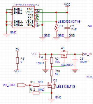 voltage conversion;
 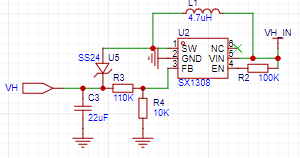 Thermal printer interface;
  Stepper motor driver.
 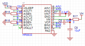 Verification results:
 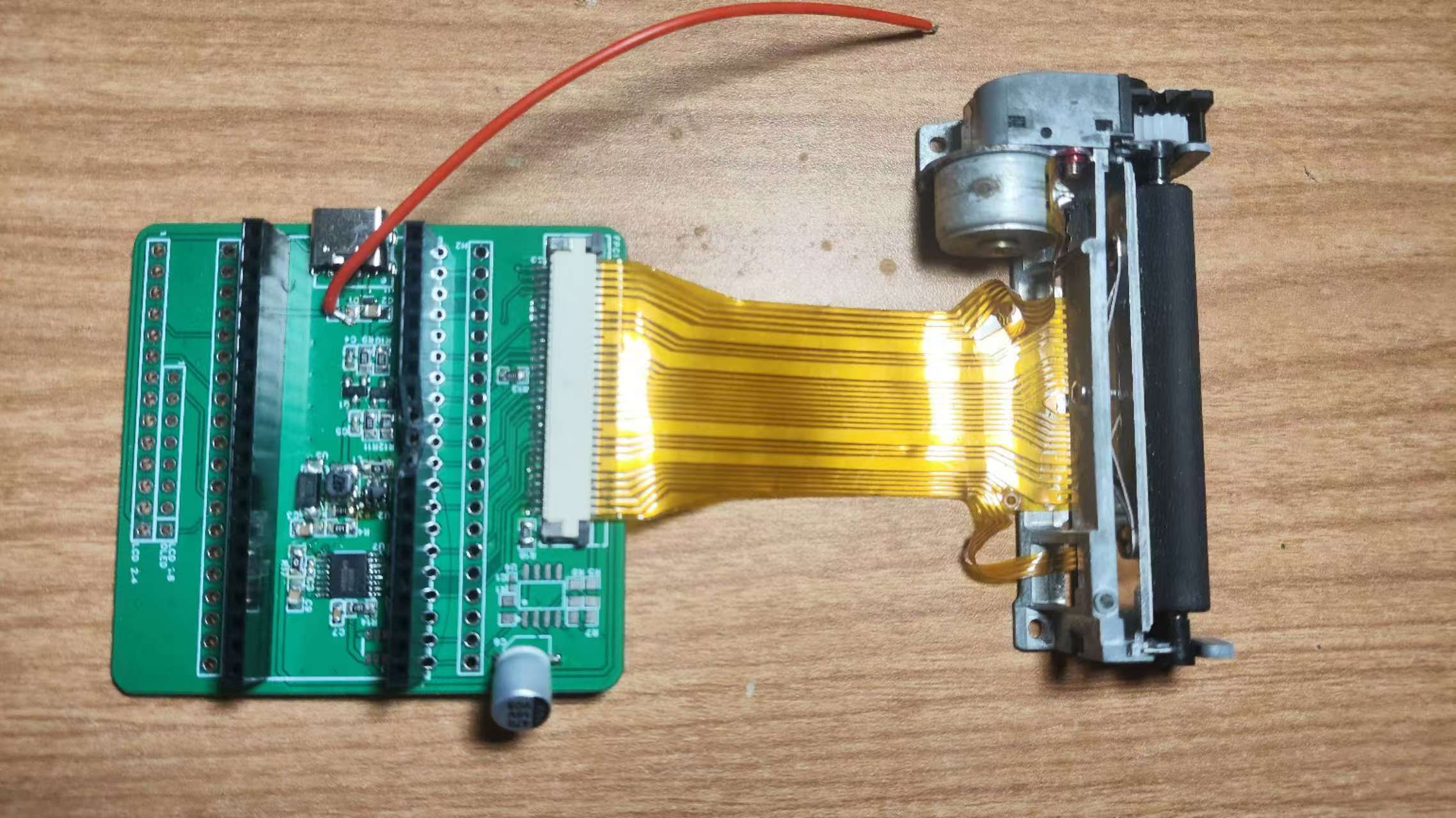 below; Power-on and driver download completed; Photo printing results as shown below .
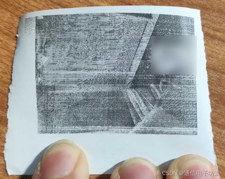


 京公网安备 11010802033920号

 CDR02BP109BCWR


