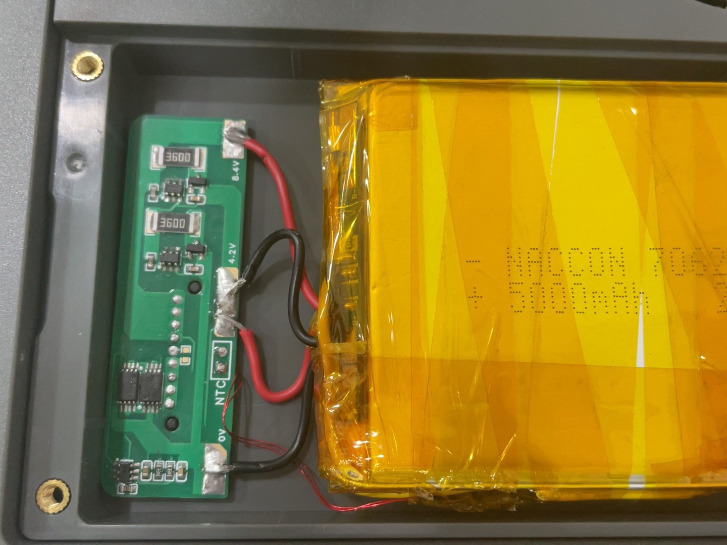
This battery protection board is compatible with the Macoxon STO1104E. Other battery models may have different interface options and require modification. Use Xiaomi 4858102 batteries; the thinner the better. Ideally, two batteries stacked together should not exceed 10mm, otherwise the back cover will be pushed up. You can also choose other batteries, as long as they don't exceed the dimensions of the battery compartment. The included accessory is a power bank clip for the back of a Rigol oscilloscope; you can download it if needed.
RGUAN DHO804 battery clip right side.stl
RGUAN DHO804 battery back clip left side.stl
PDF_Maccomico Oscilloscope Battery Protection Board - with Equalization.zip
Altium_Maccomy Oscilloscope Battery Protection Board - with Equalization.zip
PADS_McChip Oscilloscope Battery Protection Board - with Equalization.zip
BOM_McChip Oscilloscope Battery Protection Board - with Equalization.xlsx
95360
ESP32 Multifunctional Electronic Load
The ESP32 is the main controller for the electronic load. For details, please refer to the work of this expert: https://oshwhub.com/fj956391150/ESP32-shuo-kong-dian-zi-fu-zai-y
The layout of the buttons and power interface has been optimized, and the 4-pin header power interface has been removed for easier wiring.
It can use the entire ESP32S3 series of chips; some require external flash, therefore the GPIO33-37 pins need code modification. See the circuit diagram for details.
The heatsink hole spacing has been adjusted to 75*75.
0402 surface mount components have been changed to 0603 for easier surface mount. The cover
plate hasn't been drawn yet; the PCB from the expert is included.
Note that it's currently a 6-layer board design; prototyping with a 4-layer board will require modification.
PDF_ESP32 Multifunctional Electron Loader.zip
Altium_ESP32 Multifunctional Electronic Loader.zip
PADS_ESP32 Multifunctional Electronic Loader.zip
BOM_ESP32 Multifunctional Electronic Load.xlsx
95362
Nuvoton M463/M467 Development Board
The Nuvoton M463/467 development board comes with a built-in DapLink debugger.
The Nuvoton M463/467 development board comes with a built-in Daplink debugger for convenient debugging and output. It is available in two package versions: LQFP48 and LQFP64.
PDF_Nutcom M463-M467 Development Board.zip
Altium_Nuvoid M463_M467 Development Board.zip
PADS_Nuvoido M463_M467 Development Board.zip
BOM_Nutcomm M463_M467 Development Board.xlsx
95363
New definition of RD8G37Q48 core board
New definition of RD8G37Q48 core board
This is a newly defined RD8G37Q48 core board with all I/O pins exposed for easy functional verification. It features onboard buttons, a bunch of LEDs, and a power supply voltage selector (which can be adjusted via jumpers). The CH340 can be used to download and debug programs; enabling the RST pin allows for automatic program download via ISP.
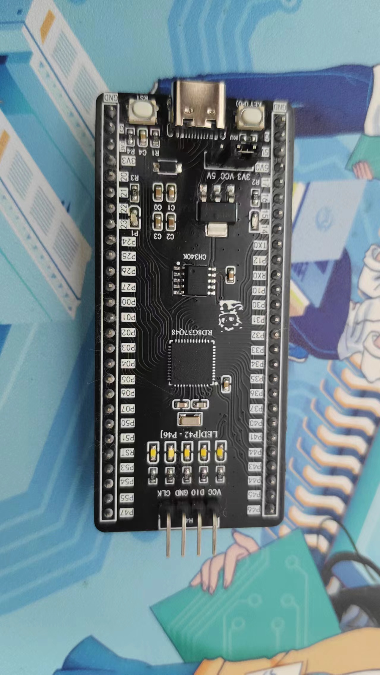

The BOM is inaccurate; please refer to the schematic.
As usual, let's turn on an LED!
vd.mp4
PDF_Newly Defined RD8G37Q48 Core Board.zip
Altium_New Definition RD8G37Q48 Core Board.zip
PADS_New Definition RD8G37Q48 Core Board.zip
BOM_New Definition of RD8G37Q48 Core Board.xlsx
95364
TLA2528-Eval
TLA2528 Evaluation Module.
This is an Evaluation Module for the TLA2528 Integrated Chip from Texas Instruments. ( This board has been verified by our team of professionals.)
5V power supply can be provided by USBC or from the external ribbon pin.
All GPIO/ADC channel pins have been drawn through the 2.54mm ribbon pin.
You can experiment with the TLA2528 IC by establishing connections between your microcontroller board and the I2C Interface of the Evaluation Module.
The address of the TLA2528 is set by R5 and R6 located on the bottom side of the board, for more information, please refer to the TLA2528 datasheet.
PDF_TLA2528-Eval.zip
Altium_TLA2528-Eval.zip
PADS_TLA2528-Eval.zip
BOM_TLA2528-Eval.xlsx
95365
MP8765-Eval
MP8765 Evaluation Module with Load Testing
This is a design verification of the MP8765 IC from Monolithic Power Systems. ( This Evaluation Module has been verified by our team of professionals)
PCB layout is mostly according to the layout recommendation section of the datasheet of MP8765.
At the right side of the board, connect a load/shunt resistor between the LOAD and PGND pad, then use a GPIO from the microcontroller to control the load switch at whatever speed (di/dt) or duty cycle you want. Then you can watch the output voltage ripple or transient performance on your scope with this officially recommended layout.
Operate with your own design considerations/risks.
PDF_MP8765-Eval.zip
Altium_MP8765-Eval.zip
PADS_MP8765-Eval.zip
BOM_MP8765-Eval.xlsx
95366
ESP32-C3-FH4 Development Board
Development board with poor signal
I've done two drafts, and it's barely usable. I just randomly put two inductors in the matching circuit, so the signal isn't very good.
It's based on the Espressif ESP32C3-FH4, and compared to the Holco C3 development board, it lacks GPIOs 11, 12, 13, 18, and 19
, supports Bluetooth and WiFi, and running LVGL on the screen works fine.

20240302_a2da8bad2063c80f_451878947248_95701196986461_published_mp4_264_fs_0_xianyu_taobao.mp4
PDF_ESP32-C3-FH4 development board.zip
Altium_ESP32-C3-FH4 development board.zip
PADS_ESP32-C3-FH4 development board.zip
BOM_ESP32-C3-FH4 Development Board.xlsx
95367
electronic


 京公网安备 11010802033920号

 1KIS124-49TT


