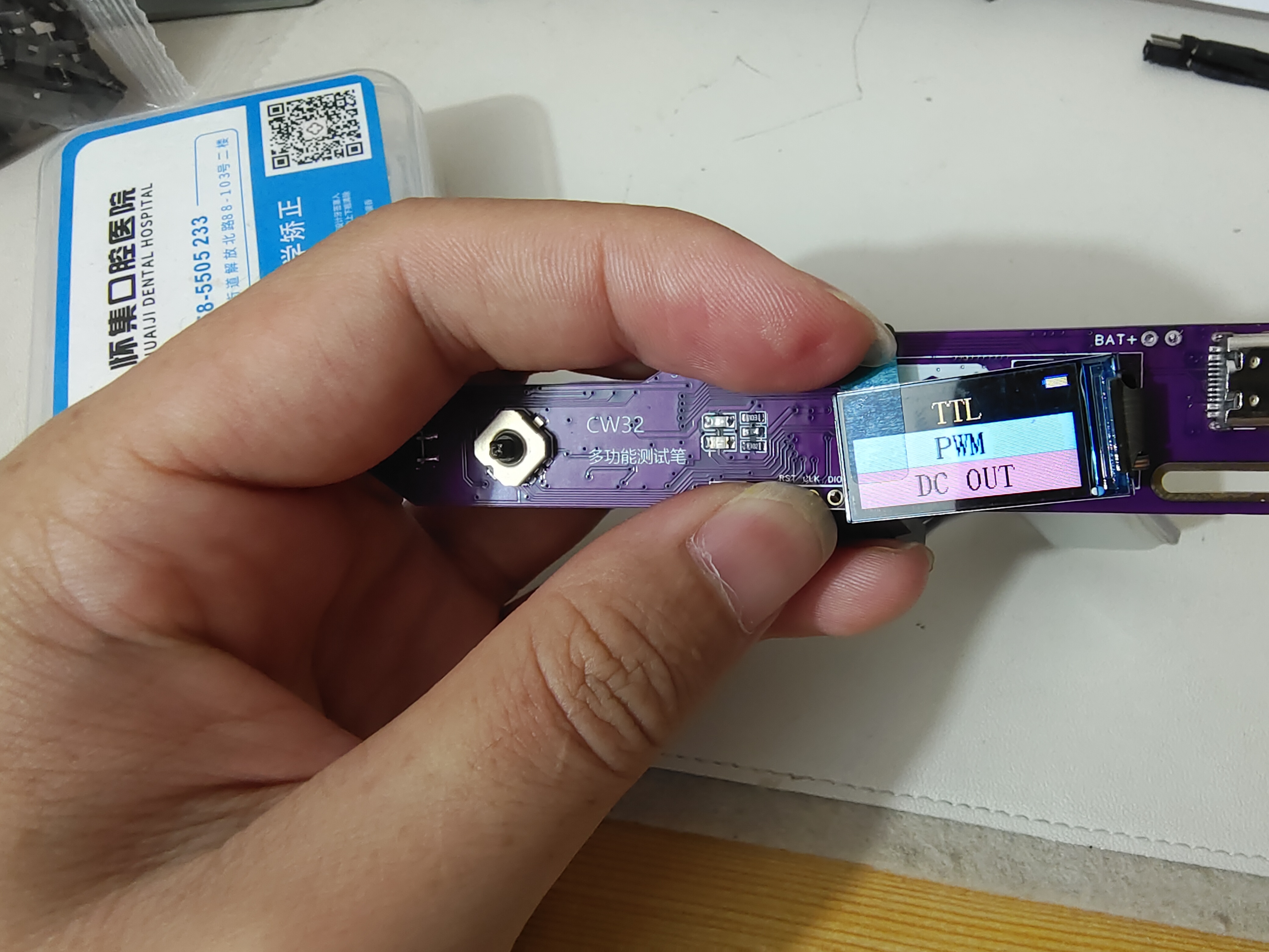
The replica multi-functional test pen uses
a CW32F030C8T6 main controller.
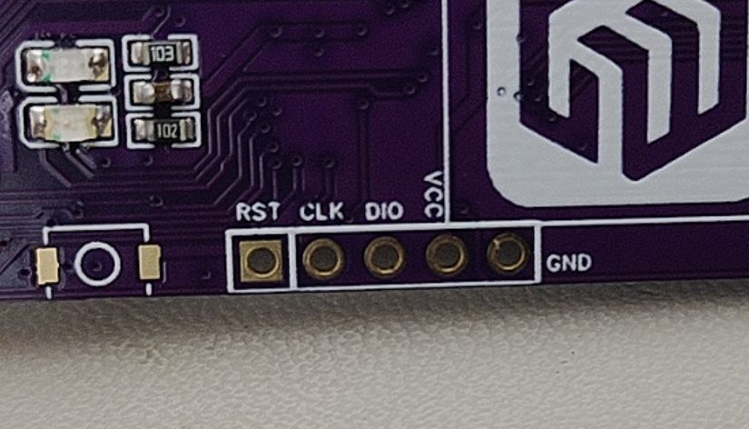
Vcc, GND, DIO, CLK, and REST are brought out separately for easy programming. A reset button is also included; this button doesn't necessarily need to be soldered on, but can be reset by shorting REST and GND with tweezers.

The signal output

circuit can output DC signals or directly output PWM signals. Essentially, it directly outputs signals from the microcontroller. The DC output level is achieved by adjusting the duty cycle of the PWM (the set signal frequency is 20kHz; for other frequencies, the DC calibration value needs to be modified), and then converting it to a "DC" signal through two stages of low-pass filtering.
However, since the output voltage of the PWM-to-DC converter is lower than the high level of the PWM, it can only output voltages from 0 to (+3.3VX), which does not meet the 0-5V target I proposed in the design. Therefore, an operational amplifier was added to double the voltage output, ultimately allowing an output voltage from 0 to 6V, meeting the target requirement. The amplified output voltage is then passed through another low-pass filter to obtain a more ideal DC signal. (This uses a positive proportional amplifier circuit to amplify the signal transmitted from the front end by a factor of 2.)
III. Signal Input Circuit
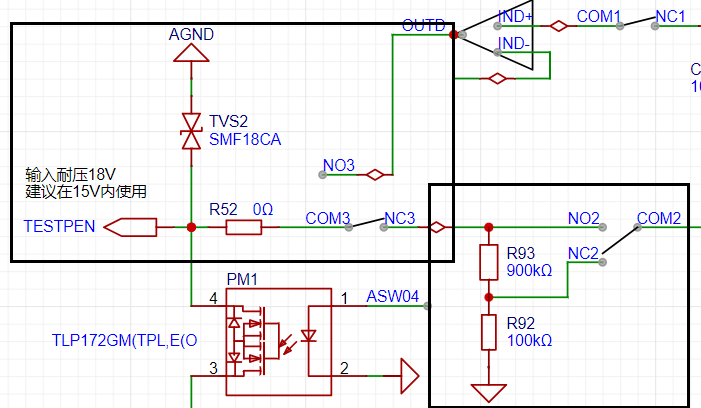
The above diagram (black box) shows the most basic signal input circuit. First, a bidirectional TVS diode protects the subsequent circuitry. Then, the signal can be selected as either input or output mode via analog switch 3 (COM3 and NC3, NO3) (default output mode). Analog switch 2 allows selection of whether the input signal is attenuated. The analog front end design is inspired by an oscilloscope, with an input impedance of 1MΩ. Like an oscilloscope, it allows selection of X1 and X10 ranges, with X10 selected by default. This design maximizes the safety of the subsequent circuitry, similar to how, when storing a multimeter with a separate power button, the range should be set to "AC voltage, maximum range".
IV. BLE Bluetooth Transmission
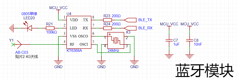
To facilitate connection between the test pen and a computer or mobile phone, I chose to use Bluetooth BLE technology for wireless data transmission.
The main reasons for not using the more common CH340 serial-to-USB converter for direct connection are as follows:
① The data cable has a certain weight and rigidity, making it less flexible to operate while wireless;
② It is not recommended to use the device with the data cable plugged in, as this will cause the floating ground of the test probes to become grounded, potentially causing a short circuit during testing;
③ Most importantly: safety! If a high voltage is input to the test probes due to operational error, and the protection circuit fails, causing the microcontroller to burn out, this high voltage could very likely travel along the data cable directly to the phone or computer, causing serious damage!
V. Physical Verification
PDF_Instruments.zip
Altium_Instruments.zip
PADS_Instruments.zip
BOM_Instruments.xlsx
95388
#Bootcamp# Simple Oscilloscope Project Based on GD32 - 1745974A
As a complete beginner, I followed JLCPCB to build a simple oscilloscope. I went through the entire product development process, from schematic diagram, PCB, board fabrication, to 3D casing modeling. I did every step very carefully.
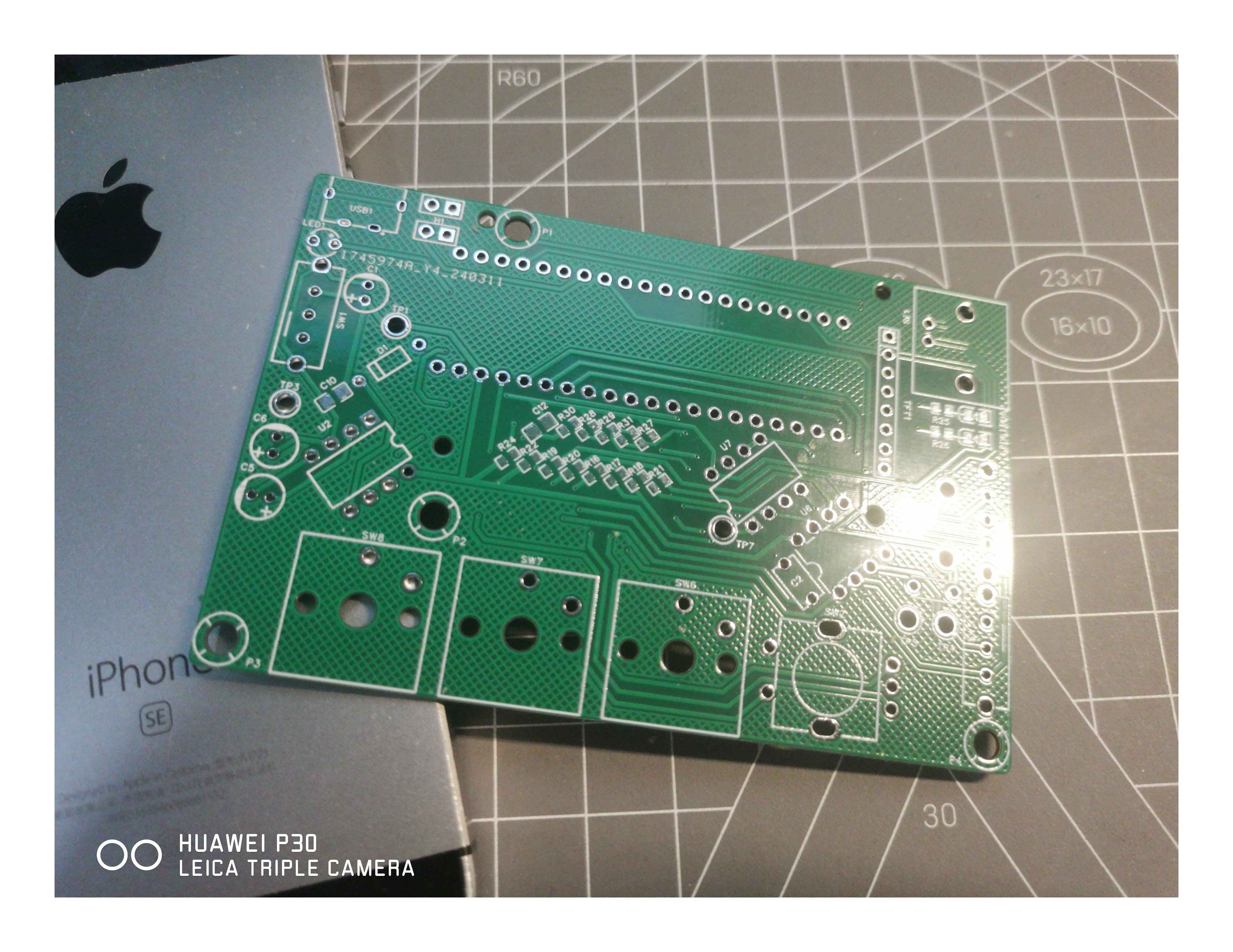


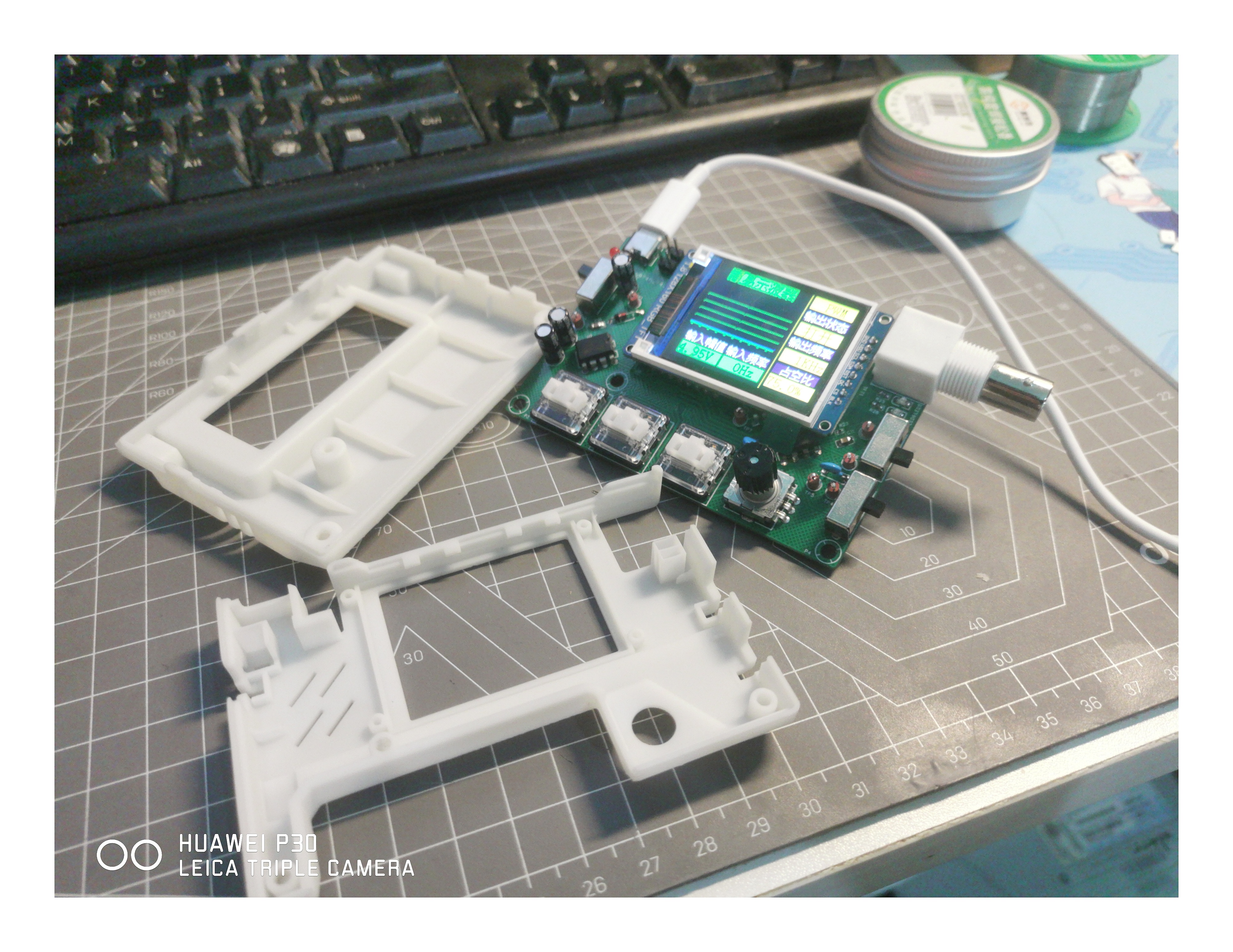

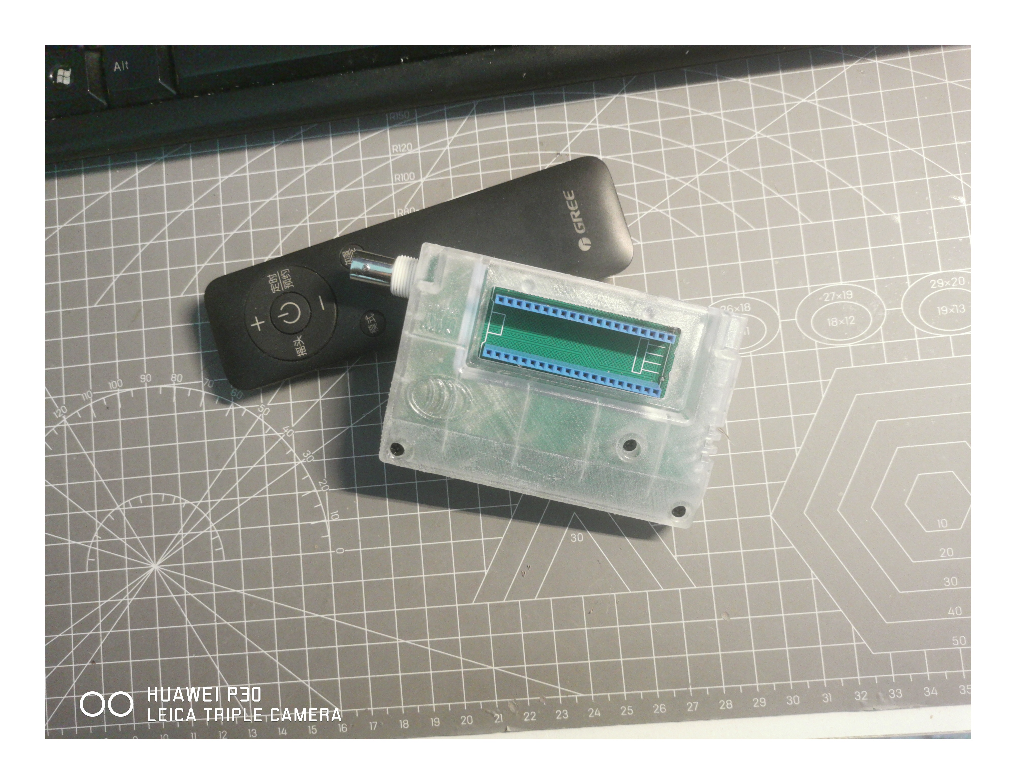
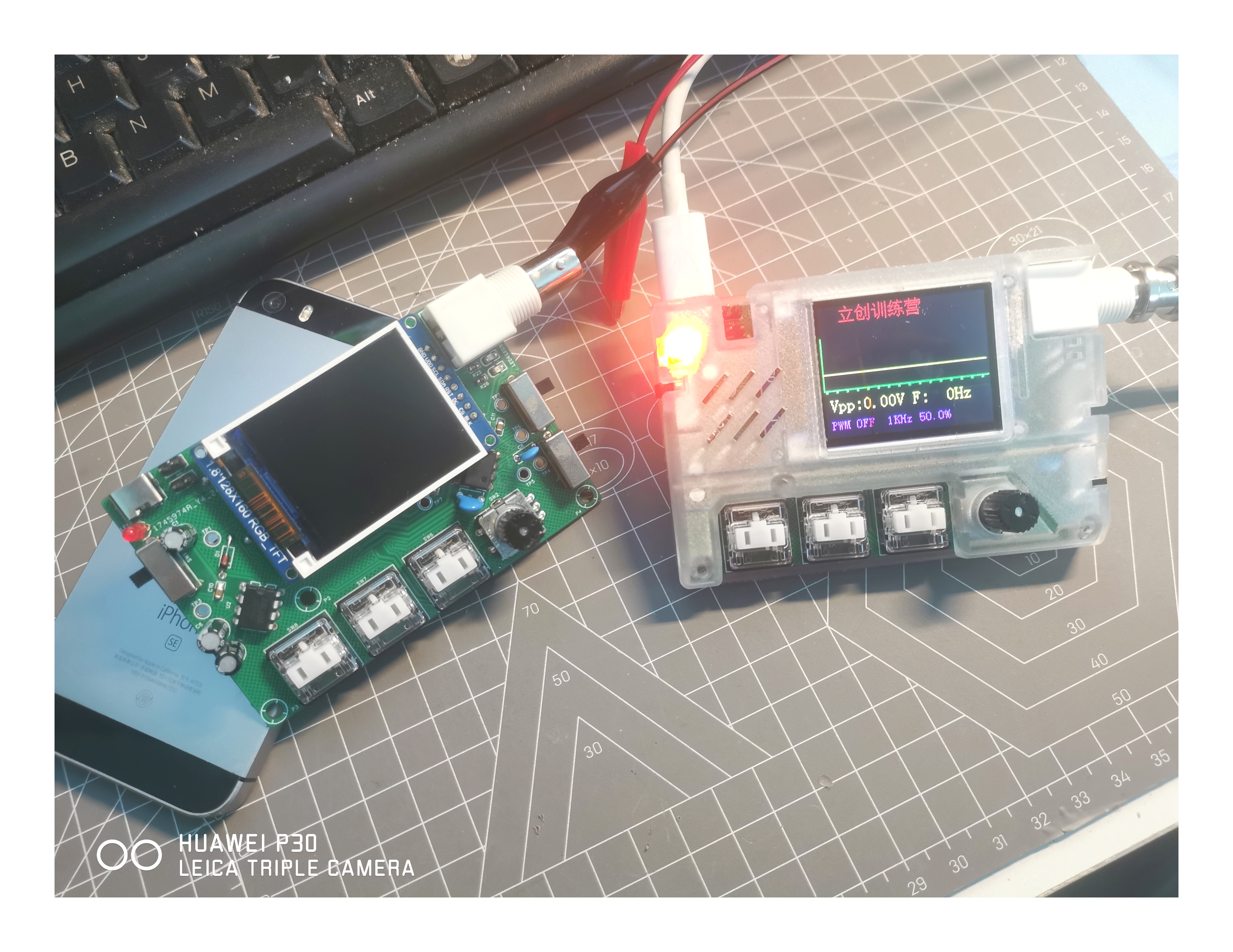
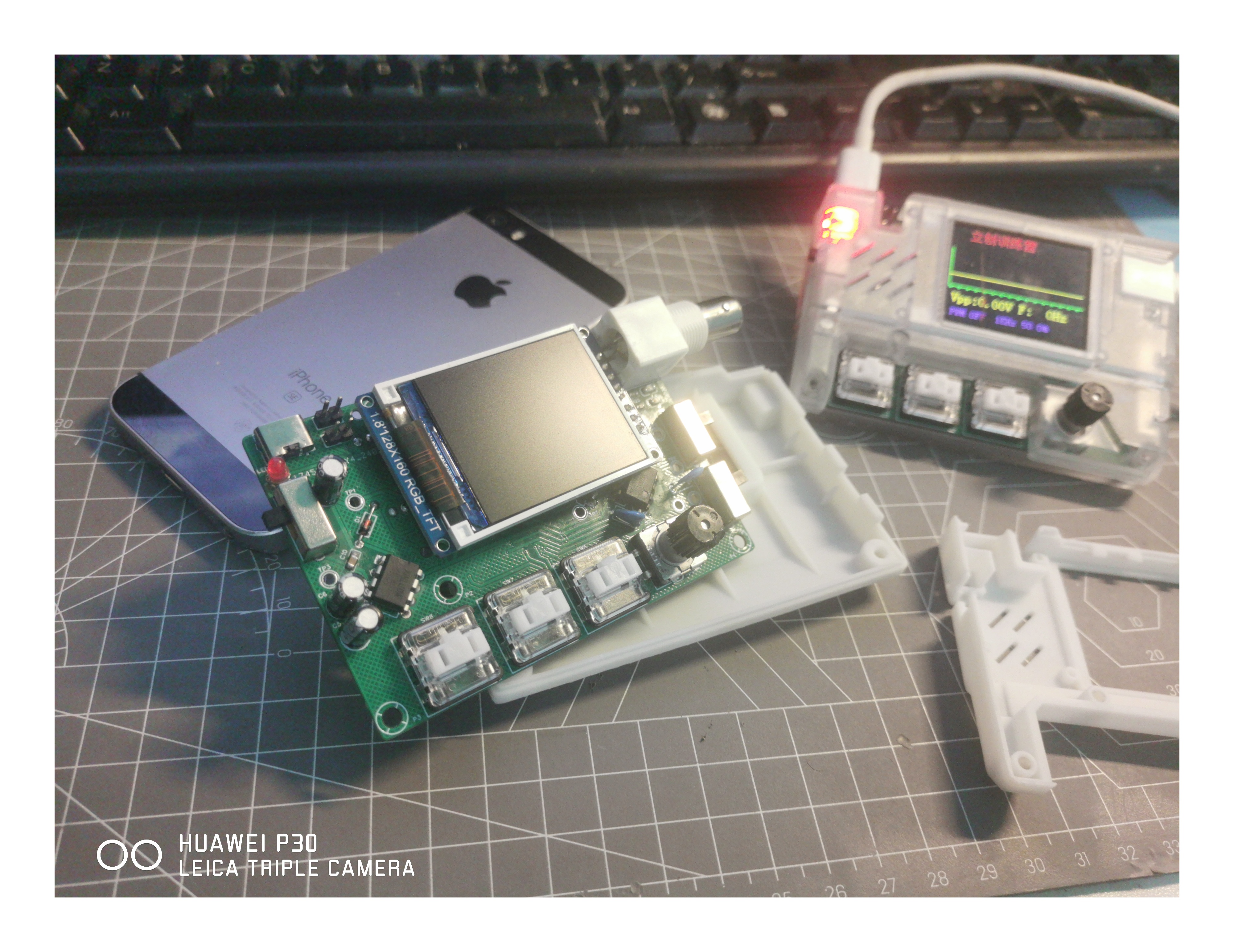
Table of Contents
Project Summary
Suggestions
Pitfalls Encountered During the Project
PCB Design:
Modeling:
Soldering:
Code
--------------------------------------------------------------------------------------------------------------------------------------------------------------
Project Summary:
First of all, I'm very grateful to JLCPCB for providing the platform and opportunity, allowing a novice like me to complete this project with the team. The project went relatively smoothly, perhaps due to good luck.
The first prototype of the casing couldn't be assembled because the capacitor height differed from the height of the model exported by JLCPCB. Also, I hadn't received the components yet, but I was eager to print the casing, resulting in a mismatch. It took a lot of time to design it, as it was done to meet mass production requirements. Later, I continued to complete the casing and even made a transparent prototype, which was exactly what I wanted.
Initially, I drew a PCB layout similar to the teacher's, but then felt it didn't suit my taste, so I modified it myself. Aesthetics are crucial. I also required myself to make a two-layer board, which was easy to achieve because the board area is large and the number of components is small.
Recommendations:
For those who want to replicate this simple oscilloscope, since I was a complete beginner myself, I'll offer some advice from a completely beginner's perspective:
The biggest challenge for most beginners is designing the PCB. When I was working on this project, I learned to design two PCBs on Bilibili beforehand, without soldering any components. This made the project much easier. If you've designed and built PCBs beforehand, you'll feel a great sense of accomplishment, which is very important. It boosts your confidence; you know how to design a PCB, and you'll have confidence. Furthermore, JLCPCB provides excellent resources, including free PCB fabrication. Think about it, since it's free, you don't have to worry about making mistakes. Just get the finished PCB and send it back for verification. Even without soldering components, it's still a real PCB, and having it there is very satisfying. Also, there are many free, high-quality JLCPCB EDA tutorials on Bilibili.
Don't get bogged down in programming knowledge. Since we're beginners, let's not worry about complex programming for now. Focus on building the device first. For programming, follow the instructor's videos. If you successfully flash the code, that's great. If not, don't be discouraged; you've taken the first step. You can gradually catch up on the programming knowledge later. Be flexible in your learning; don't get stuck on programming. It's not something you can learn in a short time. However, it's best to flash a complete code snippet. This allows you to test if the board has any problems. If not, you'll feel a greater sense of accomplishment. If there are problems, find and solve them.
Pitfalls encountered during the project:
PCB design: It's easy to make mistakes in the placement of positive and negative terminals in the schematic. My schematic was fine; the DRC was correct, and the instructor approved it. Later, after I finished the schematic and posted a screenshot in the group, someone pointed out that the capacitor's positive and negative terminals were reversed, which is quite a serious problem, according to the experienced members in the group. So, I suggest that beginners like me share our work with others, chat, and maybe an expert will spot the problem.
Modeling: I've already drawn two models. The first model was drawn ahead of time, before the components arrived, causing interference between the drawn model and the components, especially preventing the screen from being installed. I was too rushed in creating the 3D model; it's best to solder everything first and then draw the 3D model to avoid many problems. The second version is much better, except the holes for the rotary encoder were too small, which I fixed by sanding them down. I'll fix this issue in the uploaded model file later.
Soldering: I encountered many pitfalls during the process, too many to recall. The main issue I faced was in soldering. When soldering the board, you must pay close attention to the component models. I mixed up the positions of the capacitor and LED, but luckily someone pointed it out in the group chat; otherwise, the capacitor would have lit up instead of the LED. I'd also like to express my sincere gratitude to the enthusiastic members of the group for their
help with the code.
I followed the code development team for a long time, but lacking any prior experience and time, the project progressed slowly. We encountered numerous problems with the code, starting with software installation, which was quite troublesome for beginners like us. However, by following the tutorials, it was manageable, so patience is key. Code formatting and details are also prone to errors, such as semicolons and colons, and mixing up Chinese and English semicolons and colons. There are many details to pay attention to. If you're a beginner like me, I suggest flashing a complete code package first to test the board's functionality. Don't get bogged down in firmware; if your skills aren't up to par, flash a pre-built firmware – it will greatly enhance your sense of accomplishment.
I flashed firmware from a JLCPCB developer, and after that, the oscilloscope worked correctly, proving my board design was correct. I'm very grateful for their open-source firmware. Here's the link to their open-source project – it's excellent in every aspect, from the casing and firmware to the hardware; they are true masters. https://oshwhub.com/eos911/simple-oscilloscope
Finally, a big thank you to the teachers at JLCPCB! Reviewing so many documents and giving individual feedback is truly commendable. I sincerely hope JLCPCB continues to thrive.
Here's a Bilibili video: [JLCPCB - Simple Oscilloscope - Completed - Bilibili] https://b23.tv/VPnjxpv
Video demonstration-1.mp4
Full Process - 1.mp4
PDF_#bootcamp# Simple Oscilloscope Project Based on GD32 - 1745974A.zip
Altium_#bootcamp# Simple Oscilloscope Project Based on GD32 - 1745974A.zip
PADS_#bootcamp# Simple Oscilloscope Project Based on GD32 - 1745974A.zip
BOM_#Training Camp# Simple Oscilloscope Project Based on GD32 - 1745974A.xlsx
95390
INA282 Current Detection Module for the Electronic Design Contest
INA282 current sensing,
bidirectional current sensing, -2.5A to -2.5A (can be extended to -5A to 5A with a parallel resistor).
Wide common-mode range: -14V to 80V
bidirectional current detection -2.5A to 2.5A (can be extended to -5A to 5A via a parallel resistor).
External reference output connection:
Using TL431 as the external reference, the output is 2.5V.
Test results:

Under the detection conditions of 24V
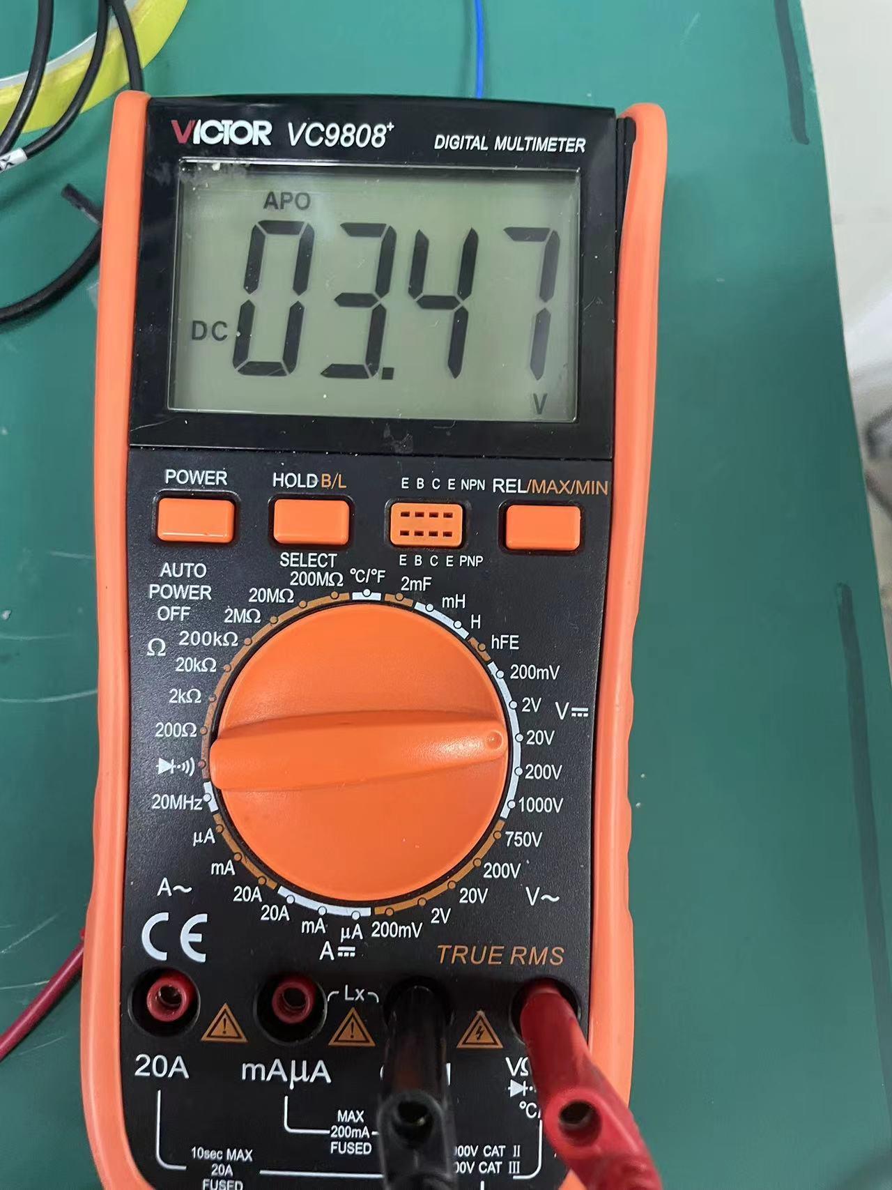
input current and a positive current of 1A, the INA282 output voltage is 3.47V.

Under the input current of 1A in reverse, the INA282 output voltage is 1.51V.
PDF_INA282 Current Detection Module for the Electronic Design Contest.zip
Altium_Electronic Design Contest Module INA282 Current Detection.zip
PADS_INA282 Current Detection Module (Electronic Design Competition) .zip
BOM_INA282 Current Detection Module (Electronic Design Competition).xlsx
95391
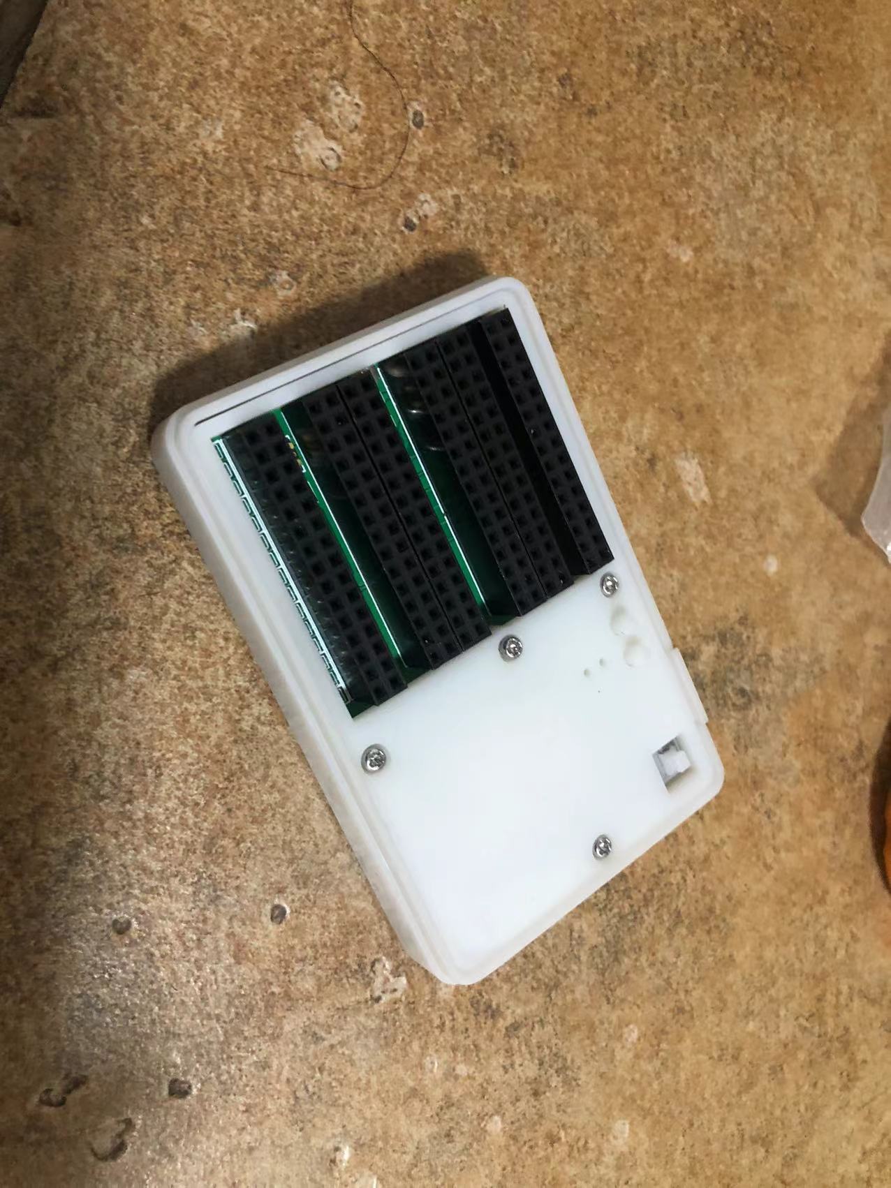
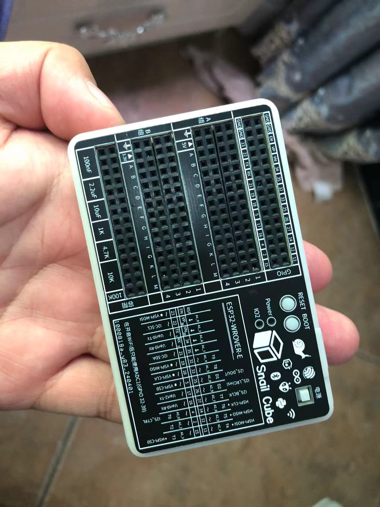
SnailCube
This is a toolbox that combines an ESP32 development board and a breadboard.
This is a development box that integrates an ESP32 development board, breadboard, and specific capacitors and resistors.

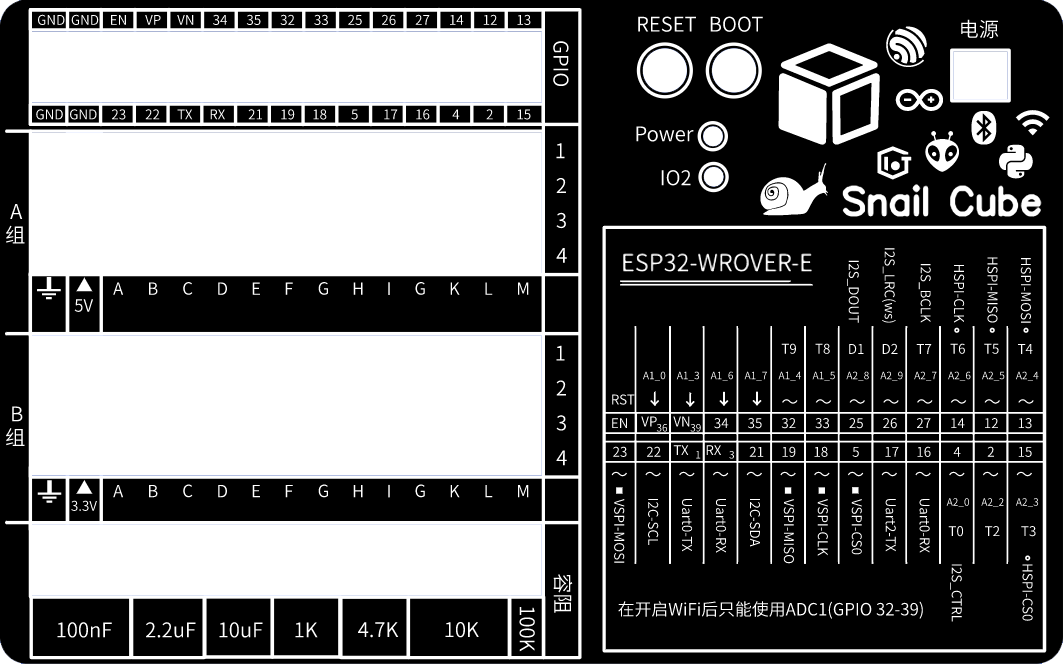
Thanks to LCSC for reviewing it. The panel PCB uses high-definition silkscreen printing, otherwise the effect would be much worse.
Shell.zip
BOM_SnailCube.xlsx
95392
The 15th Blue Bridge Cup EDA Competition Mock Test 2
Mock Exam Question 2 for the 15th Blue Bridge Cup EDA Competition (Provided by JLCPCB EDA, for reference only)
The second mock test for the 15th Blue Bridge Cup EDA competition is provided for participants to use for training and study.
The 15th Blue Bridge Cup EDA Competition Mock Test 2 (provided by JLCPCB EDA).zip
PDF_The 15th Blue Bridge Cup EDA Competition Mock Test II.zip
Altium_15th Blue Bridge Cup EDA Competition Mock Test 2.zip
PADS_15th Blue Bridge Cup EDA Competition Mock Test 2.zip
BOM_The 15th Blue Bridge Cup EDA Competition Mock Test II.xlsx
95393
electronic


 京公网安备 11010802033920号

 1.5KE8.2CAA0G


