809H adapter


PDF_809H converter.zip
Altium_809H adapter.zip
PADS_809H adapter.zip
BOM_809H adapter.xlsx
97297
Lithium battery USB-C port charging/discharging 5V output power supply board
I am Little Cabbage
Specifically, the datasheet shows the ETA9697E8A chip used, which outputs approximately 200mA-400mA of current at 5V to power low-power devices.
PDF_Lithium Battery Port C Charging/Discharging 5V Output Power Supply Board.zip
Altium lithium battery USB-C charging/discharging 5V output power supply board. (zip)
PADS_Lithium Battery Port C Charging/Discharging 5V Output Power Supply Board.zip
BOM_Lithium battery C-port charging/discharging 5V output power supply board.xlsx
97298
jms578 card opener
JMS578 Card Opener Independent Switch
JMS578 Card Opener Independent Switch
JMS578 Firmware Programmer Backup
jms578 write-protected firmware.zip
JMS578 schematic diagram.pdf
PDF_jms578 card opener.zip
Altium_jms578 card opener.zip
PADS_jms578 card opener.zip
BOM_jms578 card opener.xlsx
97299
DPLINK
Using STM32F103CBT6 as the main controller
V2.bin
PDF_DPLINK.zip
Altium_DPLINK.zip
PADS_DPLINK.zip
BOM_DPLINK.xlsx
97300
51 Minimum System Board (Surface Mount)
51 Minimum System Board (Surface Mount Small Size Version)
Verified and approved. There are two modifications: First, the switch, which was originally a half-switch, has been changed to a double-sided self-locking switch, meaning the two sides can be directly connected, eliminating the need to distinguish between the front and back. Second, the USB port has been changed to micro for greater universality.
WeChat image_20231106175229.jpg
WeChat image_20231106175241.jpg
PDF_51 Minimal System Board (Surface Mount).zip
Altium_51 Minimum System Board (Surface Mount).zip
PADS_51 Minimum System Board (Surface Mount).zip
BOM_51 Minimum System Board (Surface Mount).xlsx
97301
TPS61094 Supercapacitor Charging Board
TPS61094 Supercapacitor Charging and Discharging Board
The TPS61094 features a wide input voltage range and an output
voltage . When the TPS61094 is charging a supercapacitor in buck mode
, the charging current and termination voltage can be programmed using two external resistors
. When the TPS61094 operates in boost mode, the output voltage can be programmed using
one external resistor.
In automatic buck or boost mode (EN = 1, MODE = 1), upon
applying an input power supply, the device bypasses the input voltage to the output while simultaneously
charging the backup supercapacitor. When the input power supply is disconnected or falls below
the target output voltage, the TPS61094 enters boost mode and
regulates the output voltage via the backup supercapacitor. The TPS61094
consumes 60nA of quiescent current in this mode.
The TPS61094 supports true shutdown mode (EN = 0, MODE = 1) and
forced bypass mode (EN = 0, MODE = 0). In true shutdown mode
, the TPS61094 completely disconnects the load from the input power supply. When
forced , the TPS61094
connects the load directly to the input voltage via a bypass switch and consumes only 4nA of current, thereby extending battery
life .
PDF_TPS61094 Supercapacitor Charging Board.zip
Altium_TPS61094 Supercapacitor Charging Board.zip
PADS_TPS61094 Supercapacitor Charging Board.zip
BOM_TPS61094 Supercapacitor Charging Board.xlsx
97302
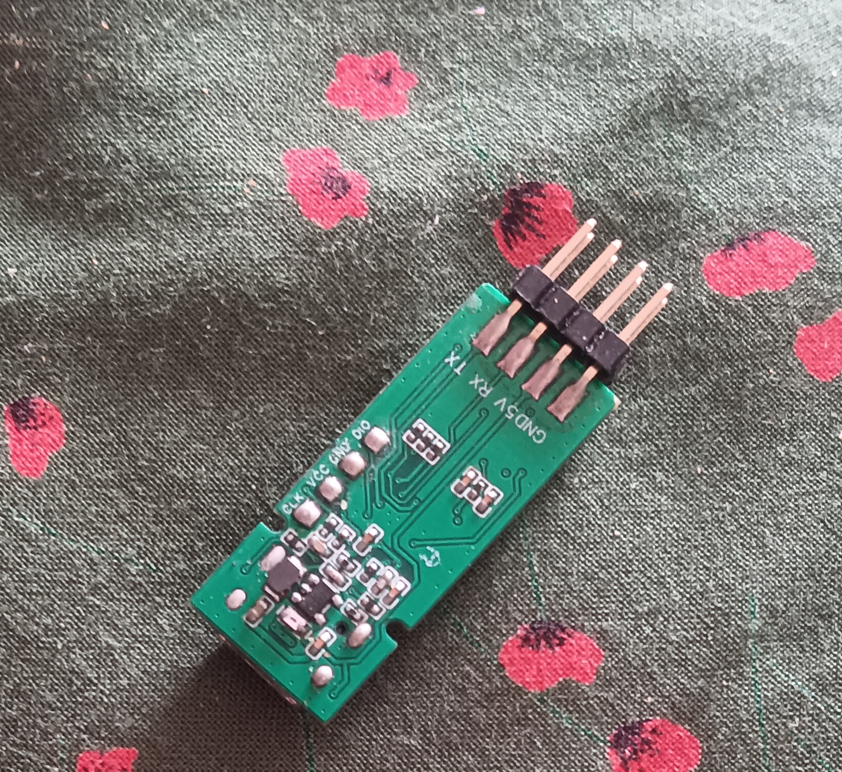
USB to TTL
USB to TTL module
The CH340E chip is used to implement USB to TTL conversion
and an LDO chip is added. Due to its own requirements, the 3.3V interface is not brought out. If needed, it can be modified to bring out the interface.
PDF_USB to TTL.zip
Altium_USB to TTL.zip
PADS_USB to TTL.zip
BOM_USB to TTL.xlsx
97304
STC12C5A60S2 Minimum System
STC12C5A60S2 Minimum System
Bilibili video link: https://www.bilibili.com/video/BV1nN4y1r7Ej/?vd_source=22f2e51672b8e25786b9935cba3c3d13
Personal chat: Thanks to JLCPCB for the colorful silkscreen printing, it's beautiful and the colors are vibrant. I hope they can hold similar events again. Secondly, it's also good preparation for my studies; I've learned a lot, thank you very much.
For those who aren't good at soldering, using reasonably priced, highly fluid solder wire will make soldering LQFP chips much easier. If you're not skilled, practice more, and you'll quickly master the technique and benefit. You can even slightly replace the micro USB port with the same device with larger pins to avoid failures that could damage your confidence.
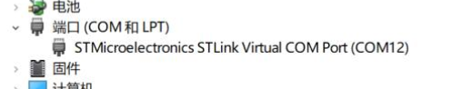
The circuit has been tested and is working properly. The chip used is STC12C5A60S2, whose instruction code is fully compatible with the traditional 8051, but is 8-12 times faster. We can see that port COM4 is connected normally, and the program can be burned normally.
The circuit diagram is shown below. For
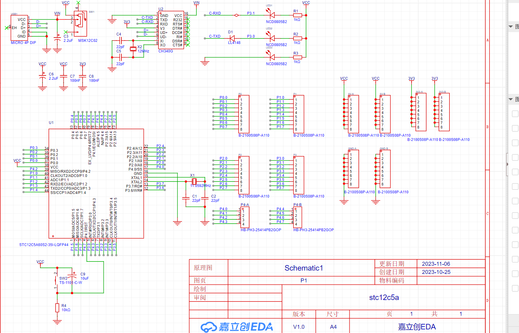
the burning process, if you can't see it clearly, you can watch the video link. I apologize for not knowing how to upload a video this time.

If this project has been helpful to you, please take a little time to give me a like. I would be very grateful to you. Please point out any shortcomings. Thank you very much.
Config_BOM_2023-10-26.json
Burning demonstration.mp4
PDF_stc12c5a60s2 Minimal System.zip
Altium_stc12c5a60s2 Minimal System.zip
PADS_stc12c5a60s2 Minimal System.zip
97305
USB HUB-V3 based on SL2.1A
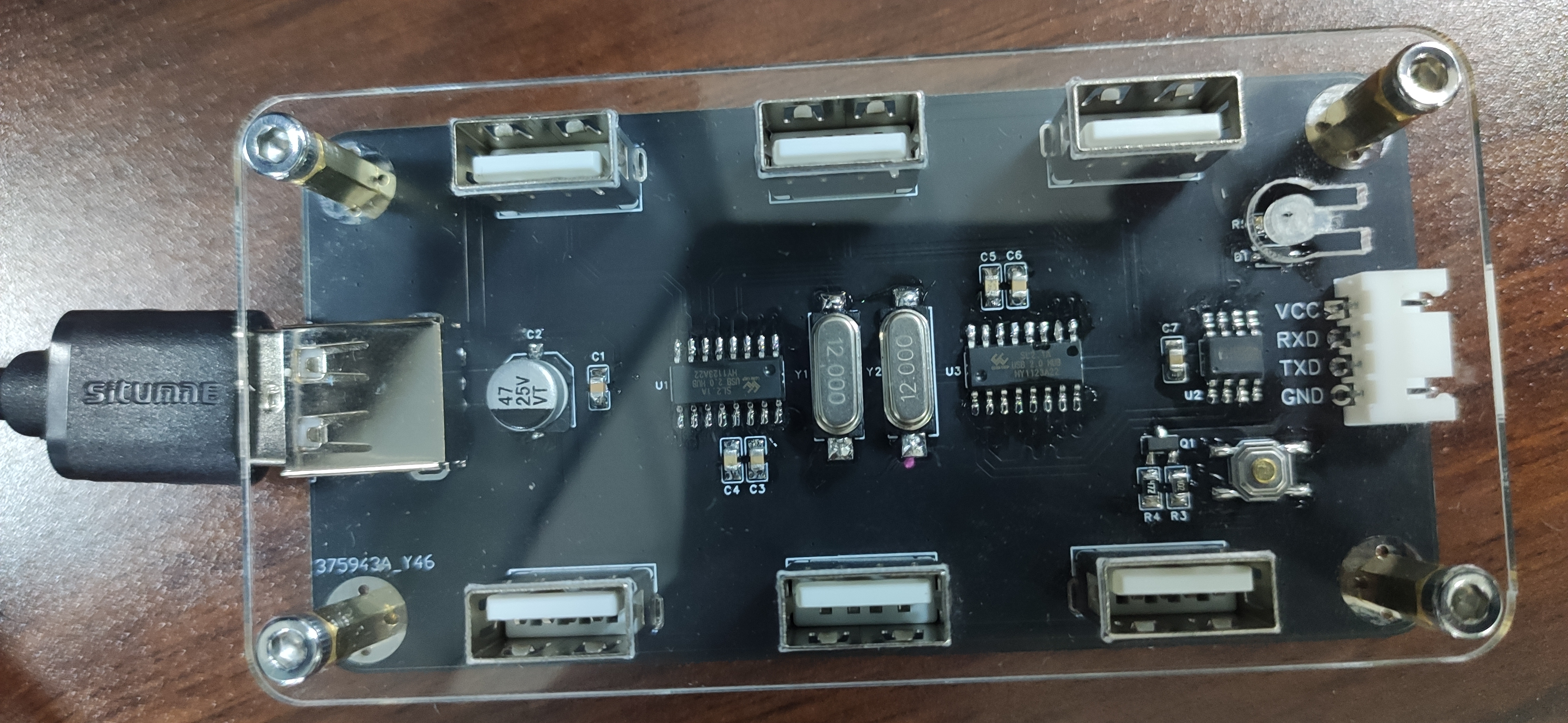
1-to-6 expansion dock based on SL2.1A
This project is a USB hub based on the SL2.1A chip. Placing it on an office desk eliminates the need to crawl under the desk to plug in USB drives. Connecting a Bluetooth receiver also makes using a Bluetooth keyboard and mouse more convenient, resulting in a cleaner desktop.
Specific functions include:
expanding one USB port to six ports
; a separate USB port; using a CH340N converter to TTL
serial port for programming; and one-click download support.
Note:
RXD and TXD have already been reversed; do not reverse them when downloading programs.
If you are not soldering a crystal oscillator, you can ground the chip's XI pin.
The switch on the CAD panel file needs to be removed and replaced with an opening. You can buy nylon posts on Taobao to insert, or use a long-handled button.
The USB hole in the panel file can be increased by 1mm; otherwise, it may be difficult to install after printing .
Upgrades:
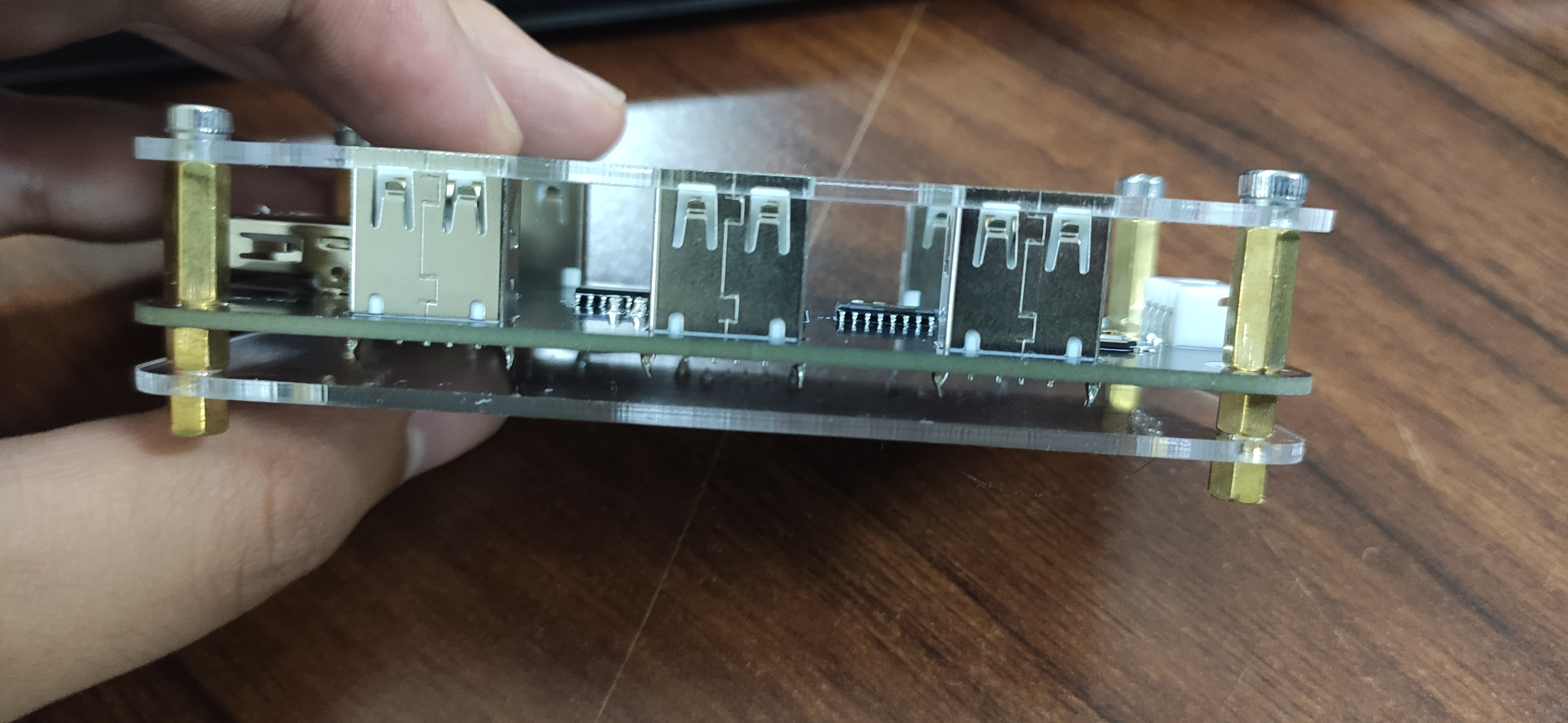
Future upgrades may include the SL2.2S, adding independent power supply and other protection circuits; the casing may be 3D printed.
After installation:
Base plate cad.dxf
panel cad.dxf
PDF_USB HUB-V3 Based on SL2.1A.zip
Altium_based_SL2.1A USB_HUB-V3.zip
PADS_based SL2.1A USB HUB-V3.zip
BOM_USB HUB-V3 based on SL2.1A.xlsx
97307
INA226 test module
The INA226 test module and measured voltage and current are normal.
The shared version of the INA226 module has modified the silkscreen, but the circuitry remains unchanged and can be used normally.
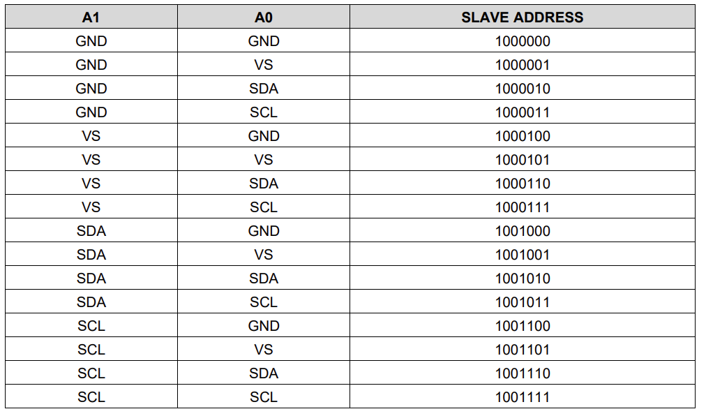
Note the INA226 parameters: input voltage and
INA226 address table.
PDF_INA226 test module.zip
Altium_INA226 test module.zip
PADS_INA226 test module.zip
BOM_INA226 test module.xlsx
97308
electronic


 京公网安备 11010802033920号

 1117V40M00000AF


