 The flashing tool is located in the example below. After entering the flashing tool, you need to manually select the above bin file:
 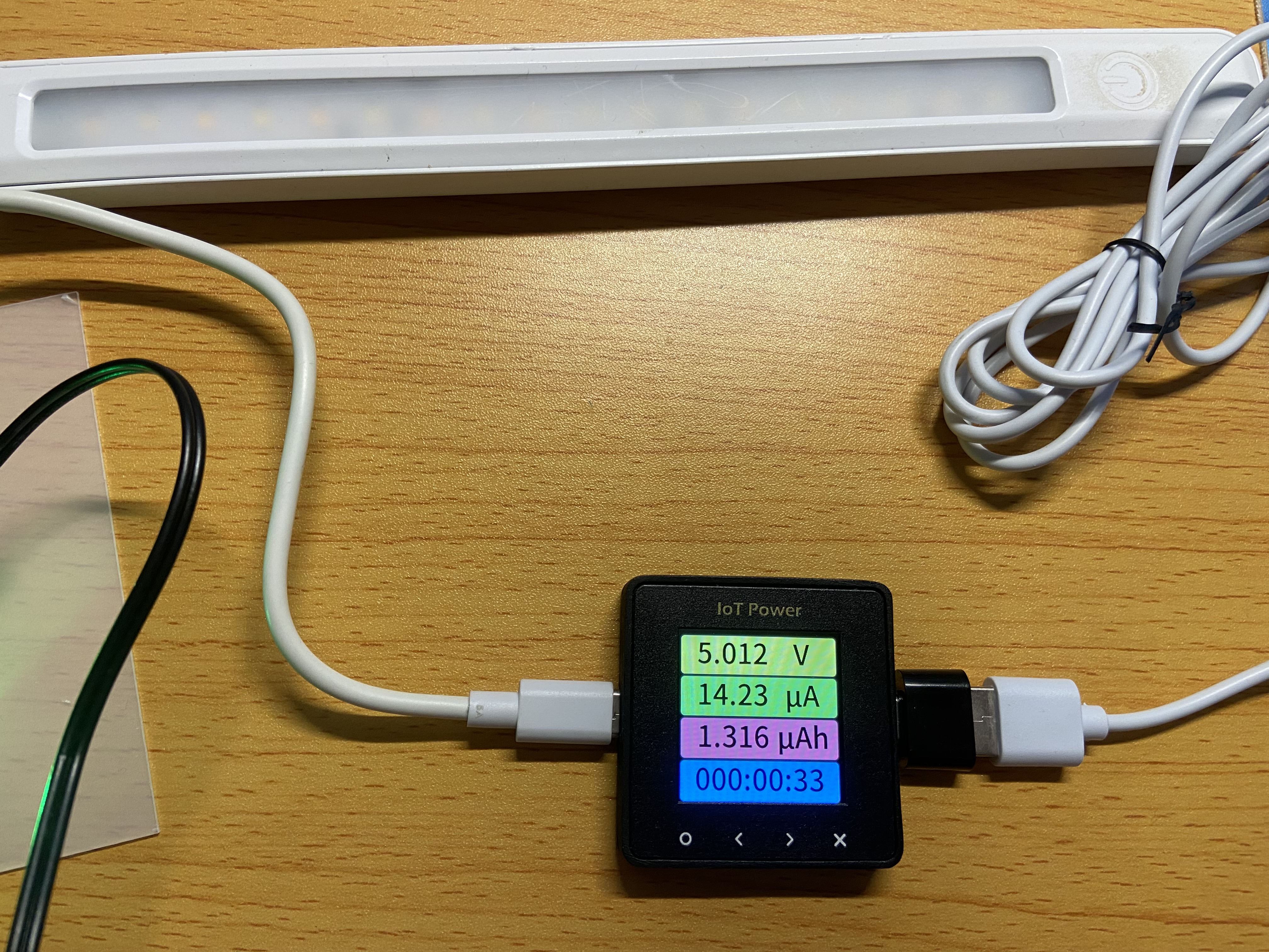 mobile phone charger power
 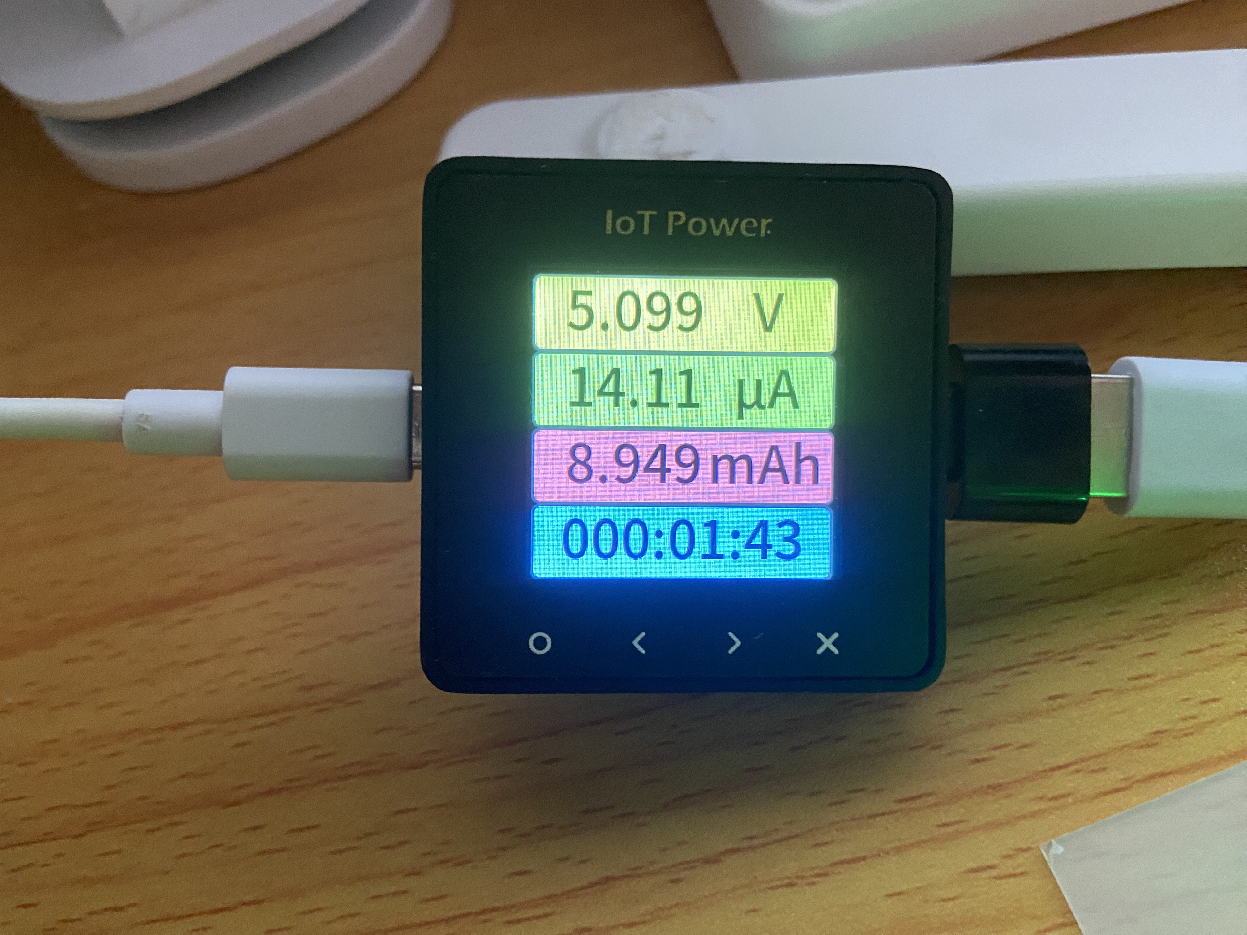 supply voltage, 5V interface
 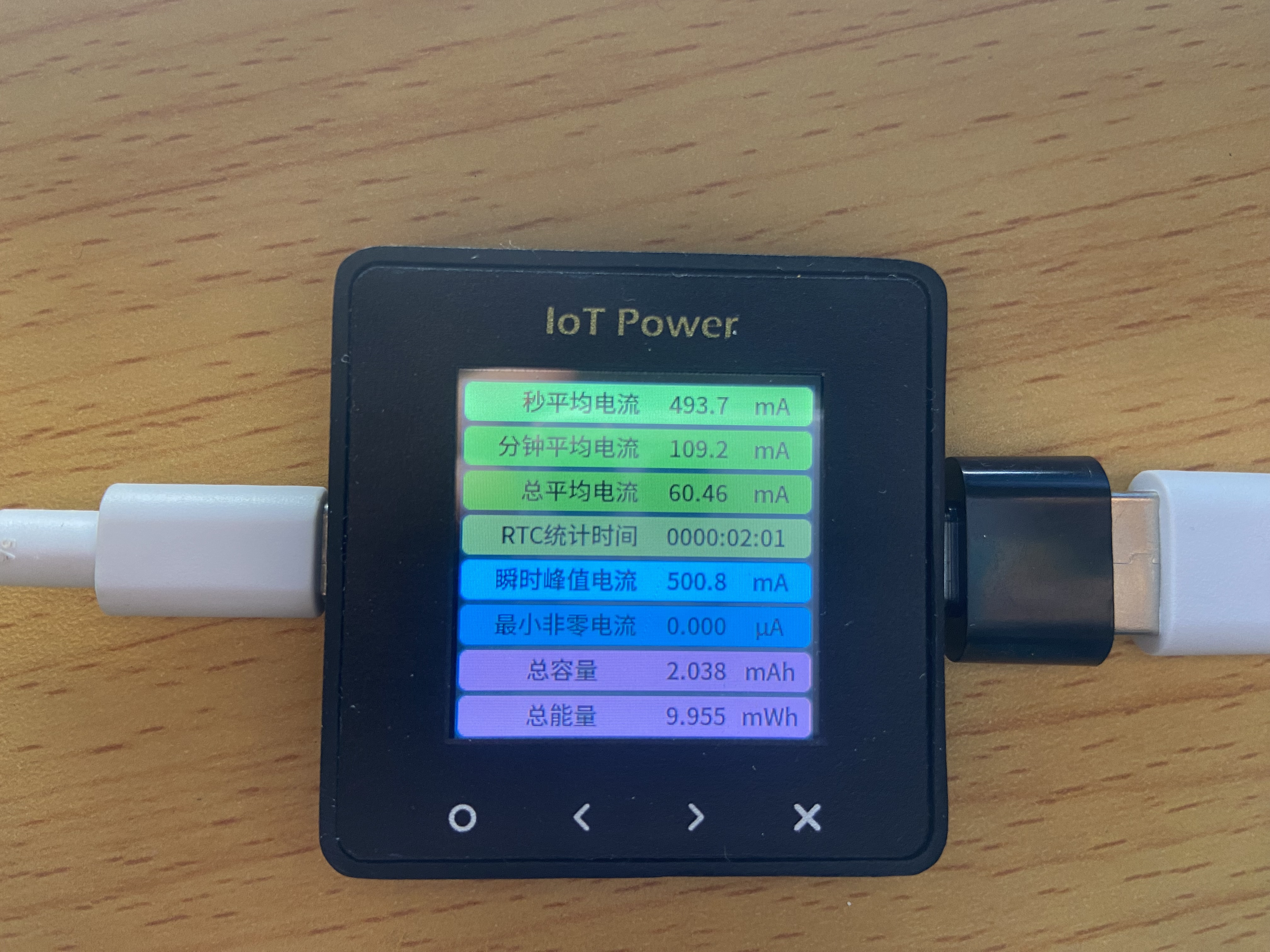 current, mobile phone charger current.
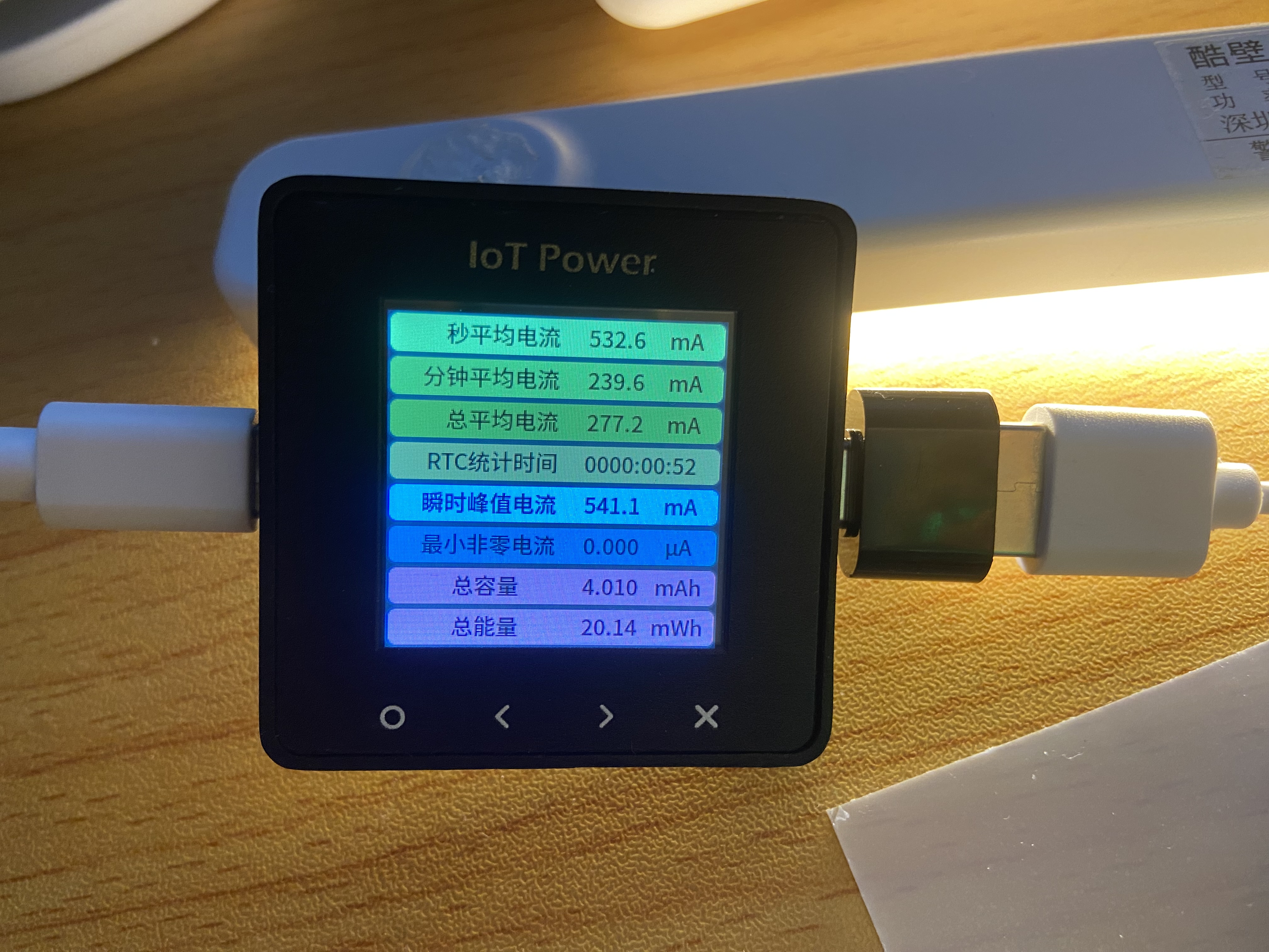
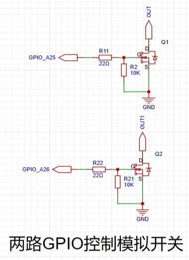 Here, an NMOS transistor - AO3400A - is used. High level turns on and low level turns off, thus becoming an analog switch to control the LED's on and off.
 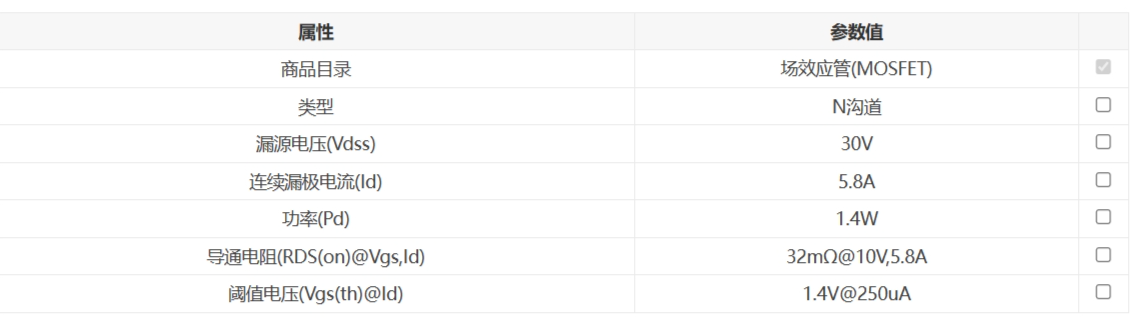 The MOS transistor is voltage-controlled to turn on, and I use it here to control the GND on and off.
  This is the official reference design
  , recommended resistor and capacitor values for common output voltages
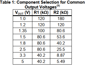
 , and a layout reference.
  Finally, pay attention to the pin orientation during soldering.
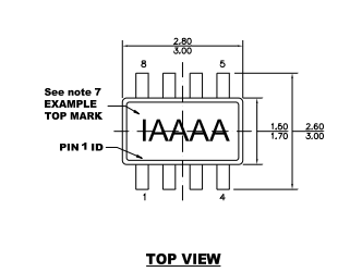


All reference designs on this site are sourced from major semiconductor manufacturers or collected online for learning and research. The copyright belongs to the semiconductor manufacturer or the original author. If you believe that the reference design of this site infringes upon your relevant rights and interests, please send us a rights notice. As a neutral platform service provider, we will take measures to delete the relevant content in accordance with relevant laws after receiving the relevant notice from the rights holder. Please send relevant notifications to email: bbs_service@eeworld.com.cn.
It is your responsibility to test the circuit yourself and determine its suitability for you. EEWorld will not be liable for direct, indirect, special, incidental, consequential or punitive damages arising from any cause or anything connected to any reference design used.
Supported by EEWorld Datasheet
EEWorld
subscription
account

EEWorld
service
account

Automotive
development
community

Robot
development
community

About Us Customer Service Contact Information Datasheet Sitemap LatestNews


Room 1530, 15th Floor, Building B,
No.18 Zhongguancun Street,
Haidian District,
Beijing, Postal Code: 100190
China
Telephone: 008610 8235 0740
 京公网安备 11010802033920号

 MSK5251-08


